EP0448086A2 - Control circuit for a monochrome picture tube - Google Patents
Control circuit for a monochrome picture tube Download PDFInfo
- Publication number
- EP0448086A2 EP0448086A2 EP91104363A EP91104363A EP0448086A2 EP 0448086 A2 EP0448086 A2 EP 0448086A2 EP 91104363 A EP91104363 A EP 91104363A EP 91104363 A EP91104363 A EP 91104363A EP 0448086 A2 EP0448086 A2 EP 0448086A2
- Authority
- EP
- European Patent Office
- Prior art keywords
- voltage
- positive
- display
- negative
- amplifier
- Prior art date
- Legal status (The legal status is an assumption and is not a legal conclusion. Google has not performed a legal analysis and makes no representation as to the accuracy of the status listed.)
- Ceased
Links
Images

Classifications
-
- G—PHYSICS
- G09—EDUCATION; CRYPTOGRAPHY; DISPLAY; ADVERTISING; SEALS
- G09G—ARRANGEMENTS OR CIRCUITS FOR CONTROL OF INDICATING DEVICES USING STATIC MEANS TO PRESENT VARIABLE INFORMATION
- G09G1/00—Control arrangements or circuits, of interest only in connection with cathode-ray tube indicators; General aspects or details, e.g. selection emphasis on particular characters, dashed line or dotted line generation; Preprocessing of data
- G09G1/002—Intensity circuits
-
- H—ELECTRICITY
- H04—ELECTRIC COMMUNICATION TECHNIQUE
- H04N—PICTORIAL COMMUNICATION, e.g. TELEVISION
- H04N5/00—Details of television systems
- H04N5/44—Receiver circuitry for the reception of television signals according to analogue transmission standards
- H04N5/57—Control of contrast or brightness
Definitions
- the invention relates to a circuit arrangement for driving a monochrome picture tube with an image signal amplifier with adjustable gain, the input signal polarity of which can be switched to positive or negative representation, different reference potentials being provided for the amplified image signals.
- the first type of representation is referred to as a negative representation
- the control circuits of picture tubes can be switched to change the display type, for what the image signals supplied to the image signal amplifier can be negated or an existing negation can be canceled.
- this is a black potential in the case of a negative representation and a white potential in the case of a positive representation.
- the reference potential in the case of a negative display is set, for example, to a value at which the screen is currently changing to the black state. Starting from this reference potential, the gain of the image signal amplifier can be adjusted to change the contrast. The greater the gain is set, the greater the output voltage swing of the image signal amplifier, and thus the contrast between the background value and the displayed symbol, with the same image signal. If the display type is switched, the reference potential for the modulation of the image signal amplifier also changes. In the case of a contrast setting that produces a gray character on a black background, this switchover causes a gray character to be displayed on a white background. In order to achieve a representation as a black character on a gray background, the brightness and / or the contrast must be adjusted.
- the object of the invention is to provide a circuit arrangement for driving a monochrome picture tube, which makes it unnecessary to readjust the contrast and / or the brightness when switching between positive and negative display.
- the invention solves this problem in a circuit arrangement of the type mentioned above in that the reference potential for positive display can be changed with the amplification of the image signal amplifier such that a predetermined maximum input voltage swing always produces an output voltage swing up to the reference potential for the negative display.
- the invention does not switch the reference potential for the positive display to a fixed, predetermined value, but rather changes it with the amplification of the image signal amplifier, that is to say with its contrast setting.
- This change in switching is carried out in the invention so that for an input signal that has a predetermined maximum input voltage swing, that is, reaches the end values for black and white, the reference potential for the positive display is shifted so that the reference potential of the negative display is reached by the output voltage swing becomes.
- the background value of the negative representation is thus achieved for a character to be displayed darkly by the output voltage swing, while the background of the positive representation is determined by a reference potential that corresponds to the value that was achieved by the output voltage swing for a character in the negative representation.
- the work area for signal control is retained, ie the switch from negative to positive display is no longer associated with a shift in the work area, so that neither Contrast still brightness after such a switch must be adjusted.
- this voltage signal can additionally control a circuit for generating a reference signal which is proportional to the reference potential for the positive display.
- the reference potentials to be set on the picture tube are derived in the control circuit from these proportional reference signals, these being used as a reference variable for regulating the reference potentials. If the dependence between the gain of the image signal amplifier and the voltage signal controlling this gain is known, the circuit for generating the reference signal for the positive display can be controlled by this voltage signal in such a way that the reference signal is shifted in accordance with the invention.
- a drive circuit for a picture tube 10 is shown.
- This circuit contains as essential components two amplifiers 11 and 12, to which the total amplification of the image signal amplifier circuit formed by them is divided, and an input stage 13.
- the input stage 13 is connected to a signal input 14 and has an inverting output 15 and a non-inverting output 16
- a changeover switch 17 is used to switch between the inverted and the non-inverted output signals of the input stage 13 and passes these signals via a coupling capacitor 18 to the first amplifier stage 11 with an input resistor 19.
- the second amplifier stage 12 amplifies the output signals of the first amplifier stage 11 and outputs the amplified image signals to the picture tube 10.
- the gain adjustment of the overall gain of the image signal amplifier circuit is carried out by means of a DC voltage signal, which is taken from an adjustable resistor 20 and is fed to a control input of the first amplifier stage 11.
- the contrast of the image representation on the picture tube 10 is thus set with this voltage signal.
- the second amplifier stage 12 has a second amplifier input which is connected to a capacitor 23, the second connection of which is at ground potential.
- the amplifier input is also connected to a current source 24, which is controlled by an amplifier 25.
- the amplifier 25 is in turn controlled at a first input by a voltage which is tapped at a voltage divider with resistors 26 and 27 and is therefore proportional to the output voltage of the amplifier stage 12, on the other hand it is switched on controlled a DC voltage, which is fed to it via a changeover switch 28.
- This DC voltage can be supplied on the one hand by a voltage divider with resistors 29 and 30, and on the other hand by an amplifier 31 which is fed back via a resistor 32.
- the control voltage, which is fed to the first amplifier stage 11, is fed to the inverting input of this amplifier 31 via a resistor 33.
- the non-inverting amplifier input is connected to a reference voltage source 34.
- control input 35 for the control circuit which is connected to the comparator 25 and supplies a synchronization signal which, as is known per se, is also used to control the line return of the picture tube 10.
- This control is not shown in FIG. 1, nor is the circuit for regulating the brightness of the picture tube via a second control input, since the invention has no necessary connection with this.
- the synchronization signal is used in the circuit arrangement shown here to switch the comparator 25 to effective during the line return of the picture tube 10, so that a control circuit with the voltage divider 26/27, the comparator 25 and the current source 24 exists on the line return times the capacitor 23 is charged. This charging takes place to a potential which is predetermined by the voltage supplied in each case by the changeover switch 28.
- the voltage output by the voltage divider with resistors 29 and 30 is to be dimensioned such that it is proportional to a reference potential for the negative representation.
- the comparator 25 outputs an output signal for charging the capacitor 23 from the current source 24 until the voltage of the voltage supplied by the voltage divider 29/30 is at its other Control input corresponds, which is output from the voltage divider 26/27.
- the resistors 29 and 30 By measuring the resistors 29 and 30, the voltage emitted by them can be dimensioned such that the potential obtained when the signals at the inputs of the comparator 25 are equal to the capacitor 23 corresponds to the reference potential for the black value in the case of a negative representation.
- the switch position of the changeover switch 28 shown in FIG. 1 is designated by N. The same applies to the switch position of the changeover switch 17.
- the changeover switch 28 When this is switched to the P position, the output signals of the input stage 13 are inverted, so that the information characters are displayed darkly on the picture tube 10 on a light background.
- the changeover switch 28 must also be switched to the position P, so that it is appropriately mechanically coupled to the changeover switch 17.
- the comparator 25 In the position P of the changeover switch 28, the comparator 25 is now supplied with a voltage which is output by the negative feedback amplifier 31 and which is related to the reference potential of the reference voltage source 34. This voltage is dependent on the contrast, since it is proportional via the amplifier 31 to the control voltage which is output by the adjustable resistor 20 for adjusting the gain or contrast.
- the resistors 32, 33 determining the gain setting of the amplifier 31 and the voltage of the reference voltage source 34.
- the voltage of the reference voltage source 34 is dependent on the voltage of the voltage divider 29/30 and thus on the reference potential of the negative representation, and on an offset which may be present in the control voltage with a minimal gain setting.
- the specified maximum input voltage swing goes into the gain setting, the ratio of the control voltage to the gain setting of the image signal amplifier and the ratio of the reference potential to the reference variable of the comparator 25.
- the output voltage of the amplifier 31 supplies the comparator 25 with another input voltage which is to be compared with the potential of the voltage divider 26/27 and leads to the charging of the capacitor 23.
- the capacitor 23 is thus charged to a different voltage, which gives the reference value for the background in the positive representation. This voltage depends on the level of the voltage supplied by the amplifier 31.
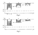
- FIG. 2 shows how the circuit shown in FIG. 1 works in a negative representation, for which the changeover switch 28 is in the N position.
- Three different signal curves are shown over time, which occur at the output of the second amplifier stage 12 and are thus input signals for driving the picture tube 10.
- the signal profiles should each correspond to an image line to be displayed on the picture tube 10 and therefore occur within a picture line time tz. They differ in the amplification set at amplifier stage 11, however, they have the same information content.
- the modulation takes place in the first signal curve between a black potential Us and a white potential Uw1, in the second signal curve between the black potential Us and a white potential Uw2 and in the third signal curve C between the black potential Us and a white potential Uw3.
- Each modulation lies between the black potential Us and a white potential Uw, which corresponds to the white value.
- the white potentials Uw1, Uw2 and Uw3 are gray potentials.
- the reference potential which is supplied to the comparator 25 for the positive display via the changeover switch 28, were only output by a differently dimensioned voltage divider, it would be dimensioned for all signal profiles A ', B' and C 'in such a way that the constant white value Uw is decisive would.
- the signal profiles A ', B' and C 'shown in FIG. 3 would then have matching white values Uw and would not reach the black value Us. The adjustment of the contrast and / or the brightness then required when switching from negative to positive display is thus avoided by the invention.
Landscapes
- Engineering & Computer Science (AREA)
- Computer Hardware Design (AREA)
- Signal Processing (AREA)
- Radar, Positioning & Navigation (AREA)
- Remote Sensing (AREA)
- Physics & Mathematics (AREA)
- Multimedia (AREA)
- General Physics & Mathematics (AREA)
- Theoretical Computer Science (AREA)
- Television Receiver Circuits (AREA)
- Controls And Circuits For Display Device (AREA)
- Liquid Crystal Display Device Control (AREA)
- Transforming Electric Information Into Light Information (AREA)
Abstract
Die Erfindung betrifft eine Schaltungsanordnung zum Ansteuern einer monochromen Bildröhre mit einem Bildsignalverstärker mit einstellbarer Verstärkung, dessen Eingangssignalpolarität zur Positiv- bzw. Negativdarstellung umschaltbar ist, wobei unterschiedliche Referenzpotentiale für die verstärkten Bildsignale vorgesehen sind. Das Referenzpotential für Positivdarstellung ist mit der Verstärkung des Bildsignalverstärkers (11, 12) so veränderbar, daß ein vorgeebener maximaler Eingangsspannungshub stets einen Ausgangsspannungshub bis zu dem Referenzpotential für die Negativdarstellung erzeugt. Dadurch erübrigt sich eine Nachregelung des Kontrastes und/oder der Helligkeit nach Umschalten von Negativ- auf Positivdarstellung.
Description
Die Erfindung betrifft eine Schaltungsanordnung zum Ansteuern einer monochromen Bildröhre mit einem Bildsignalverstärker mit einstellbarer Verstärkung, dessen Eingangssignalpolarität zur Positiv- bzw. Negativdarstellung umschaltbar ist, wobei unterschiedliche Referenzpotentiale für die verstärkten Bildsignale vorgesehen sind.The invention relates to a circuit arrangement for driving a monochrome picture tube with an image signal amplifier with adjustable gain, the input signal polarity of which can be switched to positive or negative representation, different reference potentials being provided for the amplified image signals.
Bei der Informationsdarstellung auf dem Bildschirm einer monochromen Bildröhre können helle Zeichen auf dunklem Hintergrund oder dunkle Zeichen auf hellem Hintergrund erzeugt werden. Die erste Darstellungsart wird als Negativdarstellung, die zweite als Positivdarstellung bezeichnet. Die Ansteuerschaltungen von Bildröhren sind zum Wechsel der Darstellungsart umschaltbar, wozu die dem Bildsignalverstärker zugeführten Bildsignale negiert werden können bzw. eine bestehende Negation aufgehoben werden kann. Gleichzeitig ist es dabei erforderlich, für jede Darstellungsart ein Referenzpotential für die verstärkten Bildsignale einzustellen, denn die der Bildröhre zugeführten Bildsignale müssen auf ein dem jeweiligen Hintergrundwert entsprechendes Potential bezogen werden. Bei der Schwarz-Weiß-Darstellung ist dies bei Negativdarstellung ein Schwarzpotential, bei Positivdarstellung ein Weißpotential.When displaying information on the screen of a monochrome picture tube, light characters can be created on a dark background or dark characters on a light background. The first type of representation is referred to as a negative representation, the second as a positive representation. The control circuits of picture tubes can be switched to change the display type, for what the image signals supplied to the image signal amplifier can be negated or an existing negation can be canceled. At the same time, it is necessary to set a reference potential for the amplified image signals for each type of display, because the image signals supplied to the picture tube must be related to a potential corresponding to the respective background value. In the black-and-white representation, this is a black potential in the case of a negative representation and a white potential in the case of a positive representation.
Welche Intensität bzw. Helligkeit dieses Weißpotential auf dem Bildschirm erzeugt, ist unabhängig vom Bildsignalverstärker von einer Helligkeitseinstellung abhängig, die an einem zweiten Steuereingang der Bildröhre vorgenommen wird. Das Referenzpotential bei Negativdarstellung wird beispielsweise auf einen Wert eingestellt, bei dem der Bildschirm gerade in den Schwarzzustand übergeht. Ausgehend von diesem Referenzpotential ist zur Kontraständerung die Verstärkung des Bildsignalverstärkers einstellbar. Je größer die Verstärkung eingestellt wird, umso größer wird bei gleichbleibendem Bildsignal der Ausgangsspannungshub des Bildsignalverstärkers und damit der Kontrast zwischen dem Hintergrundwert und dem dargestellten Zeichen. Wird die Darstellungsart umgeschaltet, wechselt auch das Referenzpotential für die Aussteuerung des Bildsignalverstärkers. Bei einer Kontrasteinstellung, die auf einem schwarzen Hintergrund ein graues Zeichen erzeugt, wird durch diese Umschaltung ein graues Zeichen auf einem weißen Hintergrund dargestellt. Um eine Darstellung als schwarzes Zeichen auf einem grauen Hintergrund zu erreichen, müssen die Helligkeit und/oder der Kontrast nachgeregelt werden.Which intensity or brightness this white potential generates on the screen depends on a brightness setting, which is carried out at a second control input of the picture tube, regardless of the image signal amplifier. The reference potential in the case of a negative display is set, for example, to a value at which the screen is currently changing to the black state. Starting from this reference potential, the gain of the image signal amplifier can be adjusted to change the contrast. The greater the gain is set, the greater the output voltage swing of the image signal amplifier, and thus the contrast between the background value and the displayed symbol, with the same image signal. If the display type is switched, the reference potential for the modulation of the image signal amplifier also changes. In the case of a contrast setting that produces a gray character on a black background, this switchover causes a gray character to be displayed on a white background. In order to achieve a representation as a black character on a gray background, the brightness and / or the contrast must be adjusted.
Die Aufgabe der Erfindung besteht darin, eine Schaltungsanordnung zum Ansteuern einer monochromen Bildröhre anzugeben, die ein Nachregeln des Kontrastes und/oder der Helligkeit beim Umschalten zwischen Positiv- und Negativdarstellung überflüssig macht.The object of the invention is to provide a circuit arrangement for driving a monochrome picture tube, which makes it unnecessary to readjust the contrast and / or the brightness when switching between positive and negative display.
Die Erfindung löst diese Aufgabe bei einer Schaltungsanordnung eingangs genannter Art dadurch, daß das Referenzpotential für Positivdarstellung mit der Verstärkung des Bildsignalverstärkers so veränderbar ist, daß ein vorgegebener maximaler Eingangsspannungshub stets einen Ausgangsspannungshub bis zu dem Referenzpotential für die Negativdarstellung erzeugt.The invention solves this problem in a circuit arrangement of the type mentioned above in that the reference potential for positive display can be changed with the amplification of the image signal amplifier such that a predetermined maximum input voltage swing always produces an output voltage swing up to the reference potential for the negative display.
Durch die Erfindung wird das Referenzpotential für die Positivdarstellung nicht auf einen fest vorgegebenen Wert umgeschaltet, sondern es wird mit der Verstärkung des Bildsignalverstärkers, also mit dessen Kontrasteinstellung, verändert. Diese Veränderung beim Umschalten wird bei der Erfindung so vorgenommen, daß bei einem Eingangssignal, das einen vorgegebenen maximalen Eingangsspannungshub aufweist, d.h. die Endwerte für Schwarz und Weiß erreicht, das Referenzpotential für die Positivdarstellung so verschoben wird, daß durch den Ausgangsspannungshub das Referenzpotential der Negativdarstellung erreicht wird. Damit wird für ein dunkel darzustellendes Zeichen durch den Ausgangsspannungshub der Hintergrundwert der Negativdarstellung erreicht, während der Hintergrund der Positivdarstellung durch ein Referenzpotential bestimmt wird, das dem Wert entspricht, der durch den Ausgangsspannungshub bei einem Zeichen in der Negativdarstellung erreicht wurde. Dadurch bleibt der Arbeitsbereich für die Signalaussteuerung erhalten, d.h. die Umschaltung von Negativauf Positivdarstellung ist nicht mehr mit einer Verlagerung des Arbeitsbereiches verbunden, so daß weder Kontrast noch Helligkeit nach einer solchen Umschaltung nachgeregelt werden muß.The invention does not switch the reference potential for the positive display to a fixed, predetermined value, but rather changes it with the amplification of the image signal amplifier, that is to say with its contrast setting. This change in switching is carried out in the invention so that for an input signal that has a predetermined maximum input voltage swing, that is, reaches the end values for black and white, the reference potential for the positive display is shifted so that the reference potential of the negative display is reached by the output voltage swing becomes. The background value of the negative representation is thus achieved for a character to be displayed darkly by the output voltage swing, while the background of the positive representation is determined by a reference potential that corresponds to the value that was achieved by the output voltage swing for a character in the negative representation. As a result, the work area for signal control is retained, ie the switch from negative to positive display is no longer associated with a shift in the work area, so that neither Contrast still brightness after such a switch must be adjusted.
Erfolgt die Verstärkungseinstellung des Bildsignalverstärkers durch ein Spannungssignal, so kann dieses Spannungssignal zusätzlich eine Schaltung zum Erzeugen eines dem Referenzpotential für die Positivdarstellung proportionalen Referenzsignals steuern.If the gain setting of the image signal amplifier is carried out by means of a voltage signal, this voltage signal can additionally control a circuit for generating a reference signal which is proportional to the reference potential for the positive display.
Die an der Bildröhre einzustellenden Referenzpotentiale werden in der Ansteuerschaltung von diesen proportionalen Referenzsignalen abgeleitet, wobei diese als Führungsgröße für eine Regelung der Referenzpotentiale verwendet werden. Bei bekannter Abhängigkeit zwischen der Verstärkung des Bildsignalverstärkers und dem diese Verstärkung steuernden Spannungssignal kann die Schaltung zur Erzeugung des Referenzsignals für die Positivdarstellung von diesem Spannungssignal so gesteuert werden, daß das Referenzsignal entsprechend der Erfindung verschoben wird.The reference potentials to be set on the picture tube are derived in the control circuit from these proportional reference signals, these being used as a reference variable for regulating the reference potentials. If the dependence between the gain of the image signal amplifier and the voltage signal controlling this gain is known, the circuit for generating the reference signal for the positive display can be controlled by this voltage signal in such a way that the reference signal is shifted in accordance with the invention.
Ein Ausführungsbeispiel der Erfindung wird im folgenden an Hand der Zeichnung näher erläutert. Darin zeigen:
- Fig. 1
- eine Schaltungsanordnung nach der Erfindung,
- Fig. 2
- einen beispielsweisen Bildsignalverlauf für drei verschiedene Kontrasteinstellungen und Negativdarstellung und
- Fig. 3
- die Signalverläufe nach Fig. 2 für Positivdarstellung.
- Fig. 1
- a circuit arrangement according to the invention,
- Fig. 2
- an example image signal curve for three different contrast settings and negative display and
- Fig. 3
- 2 for positive display.
In Fig. 1 ist eine Ansteuerschaltung für eine Bildröhre 10 dargestellt. Diese Schaltung enthält als wesentliche Bestandteile zwei Verstärker 11 und 12, auf die die Gesamtverstärkung der durch sie gebildeten Bildsignalverstärkerschaltung aufgeteilt ist, und eine Eingangsstufe 13. Die Eingangsstufe 13 ist mit einem Signaleingang 14 verbunden und hat einen invertierenden Ausgang 15 und einen nicht invertierenden Ausgang 16. Ein Umschalter 17 dient zum Umschalten zwischen den invertierten und den nicht invertierten Ausgangssignalen der Eingangsstufe 13 und leitet diese Signale über einen Koppelkondensator 18 auf die erste Verstärkerstufe 11 mit einem Eingangswiderstand 19.In Fig. 1, a drive circuit for a picture tube 10 is shown. This circuit contains as essential components two
Die zweite Verstärkerstufe 12 verstärkt die Ausgangssignale der ersten Verstärkerstufe 11 und gibt die verstärkten Bildsignale an die Bildröhre 10 ab.The
Die Verstärkungseinstellung der Gesamtverstärkung der Bildsignalverstärkerschaltung erfolgt durch ein Gleichspannungssignal, das an einem einstellbaren Widerstand 20 abgenommen wird und einem Steuereingang der ersten Verstärkerstufe 11 zugeführt wird. Mit diesem Spannungssignal wird also der Kontrast der Bilddarstellung auf der Bildröhre 10 eingestellt.The gain adjustment of the overall gain of the image signal amplifier circuit is carried out by means of a DC voltage signal, which is taken from an adjustable resistor 20 and is fed to a control input of the first amplifier stage 11. The contrast of the image representation on the picture tube 10 is thus set with this voltage signal.
Die zweite Verstärkerstufe 12 hat einen zweiten Verstärkereingang, der mit einem Kondensator 23 verbunden ist, dessen zweiter Anschluß auf Massepotential liegt. Der Verstärkereingang ist ferner mit einer Stromquelle 24 verbunden, die durch einen Verstärker 25 gesteuert wird. Der Verstärker 25 wird seinerseits an einem ersten Eingang durch eine Spannung angesteuert, die an einem Spannungsteiler mit Widerständen 26 und 27 abgegriffen und somit der Ausgangsspannung der Verstärkerstufe 12 proportional ist, zum anderen wird er durch eine Gleichspannung angesteuert, die ihm über einen Umschalter 28 zugeführt wird. Diese Gleichspannung kann einerseits von einem Spannungsteiler mit Widerständen 29 und 30, andererseits von einem Verstärker 31 geliefert werden, der über einen Widerstand 32 gegengekoppelt ist. Dem invertierenden Eingang dieses Verstärkers 31 wird die Steuerspannung, die der ersten Verstärkerstufe 11 zugeführt wird, über einen Widerstand 33 zugeführt. Der nicht invertierende Verstärkereingang ist mit einer Referenzspannungsquelle 34 verbunden.The
Es ist ferner ein Steuereingang 35 für die Ansteuerschaltung vorgesehen, der mit dem Vergleicher 25 verbunden ist und ein Synchronisationssignal liefert, das, wie an sich bekannt, auch zum Steuern des Zeilenrücklaufs der Bildröhre 10 verwendet wird. Diese Steuerung ist in Fig. 1 nicht dargestellt, ebenfalls nicht dargestellt ist die Schaltung zur Helligkeitsregelung der Bildröhre über einen zweiten Steuereingang, da die Erfindung hiermit keinen notwendigen Zusammenhang hat. Das Synchronisationssignal wird bei der hier gezeigten Schaltungsanordnung dazu verwendet, den Vergleicher 25 jeweils während des Zeilenrücklaufs der Bildröhre 10 wirksam zu schalten, so daß während der Zeilenrücklaufzeiten ein Regelkreis mit dem Spannungsteiler 26/27, dem Vergleicher 25 und der Stromquelle 24 existiert, an dem der Kondensator 23 aufgeladen wird. Dieses Aufladen erfolgt auf ein Potential, das durch die jeweils von dem Umschalter 28 gelieferte Spannung vorgegeben ist. Die von dem Spannungsteiler mit den Widerständen 29 und 30 abgegebene Spannung ist so zu bemessen, daß sie einem Referenzpotential für die Negativdarstellung proportional ist. Der Vergleicher 25 gibt so lange ein Ausgangssignal zum Aufladen des Kondensators 23 aus der Stromquelle 24 ab, bis die von dem Spannungsteiler 29/30 gelieferte Spannung der Spannung an seinem anderen Steuereingang entspricht, die von dem Spannungsteiler 26/27 abgegeben wird. Durch Bemessen der Widerstände 29 und 30 kann die von diesen abgegebene Spannung so dimensioniert werden, daß das bei Gleichheit der Signale an den Eingängen des Vergleichers 25 am Kondensator 23 erhaltene Potential dem Referenzpotential für den Schwarzwert bei Negativdarstellung entspricht. Entsprechend ist die in Fig. 1 gezeigte Schalterstellung des Umschalters 28 mit N bezeichnet. Gleiches gilt für die Schalterstellung des Umschalters 17. Wenn dieser auf die Stellung P umgeschaltet wird, so werden die Ausgangssignale der Eingangsstufe 13 invertiert, so daß die Informationszeichen mit der Bildröhre 10 dunkel auf hellem Hintergrund dargestellt werden. Hierzu muß auch der Umschalter 28 auf die Stellung P umgeschaltet werden, so daß er mit dem Umschalter 17 zweckmäßig mechanisch gekoppelt ist. In der Stellung P des Umschalters 28 wird dem Vergleicher 25 nun eine Spannung zugeführt, die von dem gegengekoppelten Verstärker 31 abgegeben und auf das Referenzpotential der Referenzspannungsquelle 34 bezogen ist. Diese Spannung ist kontrastabhängig, da sie über den Verstärker 31 der Steuerspannung proportional ist, die von dem einstellbaren Widerstand 20 zur Verstärkungs- bzw. Kontrasteinstellung abgegeben wird.There is also a
Sie wird durch die die Verstärkungseinstellung des Verstärkers 31 bestimmenden Widerstände 32, 33 und die Spannung der Referenzspannungsquelle 34 dimensioniert. Die Spannung der Referenzspannungsquelle 34 ist bei dieser Dimensionierung von der Spannung des Spannungsteilers 29/30 und damit vom Referenzpotential der Negativdarstellung abhängig, sowie von einem in der Steuerspannung möglicherweise vorhandenen Offset bei minimaler Verstärkungseinstellung. In die Verstärkungseinstellung gehen der vorgegebene maximale Eingangsspannungshub, das Verhältnis von Steuerspannung zur Verstärkungseinstellung des Bildsignalverstärkers sowie das Verhältnis von Referenzpotential zu der Führungsgröße des Vergleichers 25 ein.It is dimensioned by the
Durch die Ausgangsspannung des Verstärkers 31 wird dem Vergleicher 25 eine andere Eingangsspannung zugeführt, die mit dem Potential des Spannungsteilers 26/27 zu vergleichen ist und zur Aufladung des Kondensators 23 führt. Der Kondensator 23 wird somit auf eine andere Spannung aufgeladen, die den Bezugswert für den Hintergrund bei Positivdarstellung angibt. Diese Spannung hängt von der Höhe der jeweils vom Verstärker 31 gelieferten Spannung ab.The output voltage of the
In Fig. 2 ist dargestellt, wie die in Fig. 1 gezeigte Schaltung bei Negativdarstellung arbeitet, für die sich der Umschalter 28 in der Stellung N befindet. Es sind drei verschiedene Signalverläufe über der Zeit dargestellt, die am Ausgang der zweiten Verstärkerstufe 12 auftreten und somit Eingangssignale zur Ansteuerung der Bildröhre 10 sind. Die Signalverläufe sollen jeweils einer auf der Bildröhre 10 darzustellenden Bildzeile entsprechen und treten daher innerhalb einer Bildzeilenzeit tz auf. Sie unterscheiden sich durch die an der Verstärkerstufe 11 jeweils eingestellte Verstärkung, jedoch stimmen sie in ihrem Informationsgehalt überein. Die Aussteuerung erfolgt bei dem ersten Signalverlauf zwischen einem Schwarzpotential Us und einem Weißpotential Uw1, bei dem zweiten Signalverlauf zwischen dem Schwarzpotential Us und einem Weißpotential Uw2 und bei dem dritten Signalverlauf C zwischen dem Schwarzpotential Us und einem Weißpotential Uw3. Jede Aussteuerung liegt zwischen dem Schwarzpotential Us und einem Weißpotential Uw, das dem Weißwert entspricht. Somit sind die Weißpotentiale Uw1, Uw2 und Uw3 Graupotentiale.FIG. 2 shows how the circuit shown in FIG. 1 works in a negative representation, for which the
Wenn die Signalverläufe nach Fig. 2 durch Umschalten des Umschalters 17 auf die Schalterstellung P (Fig. 1) invertiert werden, so ergibt sich die in Fig. 3 gezeigte Situation. Die Form der Signalverläufe A', B' und C' ist spiegelbildlich zu der Form der Signalverläufe A, B und C in Fig. 2. Dies gilt auch für die Höhe der Weißpotentiale Uw1, Uw2 und Uw3, die so bemessen ist, daß mit der jeweiligen, kontrastabhängig eingestellten Aussteuerung stets der Schwarzwert Us erreicht wird.If the signal curves according to FIG. 2 are inverted by switching the switch 17 to the switch position P (FIG. 1), the situation shown in FIG. 3 results. The shape of the waveforms A ', B' and C 'is a mirror image of the shape of the waveforms A, B and C in Fig. 2. This also applies to the height of the white potentials Uw1, Uw2 and Uw3, which is dimensioned so that with the black level Us, which is set as a function of the contrast, is always reached.
Würde das Bezugspotential, das für die Positivdarstellung über den Umschalter 28 an den Vergleicher 25 geliefert wird, lediglich von einem anders dimensionierten Spannungsteiler abgegeben, so wäre es für alle Signalverläufe A', B' und C' so bemessen, daß der konstante Weißwert Uw maßgebend wäre. Die in Fig. 3 dargestellten Signalverläufe A', B' und C' würden dann übereinstimmende Weißwerte Uw haben und nicht den Schwarzwert Us erreichen. Die dann erforderliche Nachstellung des Kontrastes und/oder der Helligkeit beim Umschalten von Negativ- auf Positivdarstellung wird also durch die Erfindung vermieden.If the reference potential, which is supplied to the
Claims (2)
Applications Claiming Priority (2)
| Application Number | Priority Date | Filing Date | Title |
|---|---|---|---|
| DE4008946 | 1990-03-20 | ||
| DE19904008946 DE4008946C1 (en) | 1990-03-20 | 1990-03-20 | Control circuit for monochrome picture tube - changes positive polarity reference potential with amplification of picture signal amplifier |
Publications (2)
| Publication Number | Publication Date |
|---|---|
| EP0448086A2 true EP0448086A2 (en) | 1991-09-25 |
| EP0448086A3 EP0448086A3 (en) | 1992-03-04 |
Family
ID=6402652
Family Applications (1)
| Application Number | Title | Priority Date | Filing Date |
|---|---|---|---|
| EP19910104363 Ceased EP0448086A3 (en) | 1990-03-20 | 1991-03-20 | Control circuit for a monochrome picture tube |
Country Status (2)
| Country | Link |
|---|---|
| EP (1) | EP0448086A3 (en) |
| DE (1) | DE4008946C1 (en) |
Families Citing this family (1)
| Publication number | Priority date | Publication date | Assignee | Title |
|---|---|---|---|---|
| JPH11205709A (en) * | 1998-01-08 | 1999-07-30 | Sony Corp | Display device |
Family Cites Families (3)
| Publication number | Priority date | Publication date | Assignee | Title |
|---|---|---|---|---|
| US3249694A (en) * | 1962-08-09 | 1966-05-03 | Hazeltine Research Inc | Black level stabilization system for a television receiver |
| US4679087A (en) * | 1984-03-12 | 1987-07-07 | Loge/Dunn Instruments, Inc. | Method and apparatus for photographing video images of either polarity without CRT brightness or contrast readjustment |
| EP0392100A1 (en) * | 1989-04-13 | 1990-10-17 | International Business Machines Corporation | Cathode ray tube display apparatus with improved intensity control |
-
1990
- 1990-03-20 DE DE19904008946 patent/DE4008946C1/en not_active Expired - Lifetime
-
1991
- 1991-03-20 EP EP19910104363 patent/EP0448086A3/en not_active Ceased
Also Published As
| Publication number | Publication date |
|---|---|
| EP0448086A3 (en) | 1992-03-04 |
| DE4008946C1 (en) | 1991-06-20 |
Similar Documents
| Publication | Publication Date | Title |
|---|---|---|
| DE69414081T2 (en) | Amplifier with offset DC voltage correction | |
| DE2845816C2 (en) | Circuit for increasing the contrast of a video signal | |
| DE2252181C3 (en) | Video amplifier for a color television monitor | |
| DE69125433T2 (en) | Video signal processing circuit | |
| DE19922540A1 (en) | Image display has image output unit, amplifier unit for amplifying image signal with gain with frequency characteristic, controlled variable inductor defining frequency characteristic | |
| DE864887C (en) | Automatic gain control | |
| DE2819774C3 (en) | Brightness controller for a transmission channel for processing a video signal | |
| DE3632486C2 (en) | ||
| DE3744110C2 (en) | ||
| EP0448086A2 (en) | Control circuit for a monochrome picture tube | |
| DE69431138T2 (en) | Non-linear video signal processing | |
| DE4316526B4 (en) | Transmitter with a controllable power amplifier | |
| EP0750807A1 (en) | Amplifier | |
| DE68921427T2 (en) | Device for restoring the direct current. | |
| DE1276134B (en) | Wobble transmitter with electronic frequency control | |
| DE69734375T2 (en) | Image display device with bus-controlled compensation circuit using a pulse width modulation signal # | |
| DE2749767B2 (en) | Circuit arrangement for controlling the brightness of light-emitting diodes in light-emitting diode fields | |
| DE4315092C2 (en) | Display monitor | |
| DE2018923A1 (en) | Fast current switching amplifier (deflection amplifier) | |
| EP0793159B1 (en) | Circuit for generation of a supply voltage | |
| DE69322699T2 (en) | Alarm circuit for a telephone set | |
| DE3242127C2 (en) | ||
| DE2611274C3 (en) | Control amplifier circuit with balancing effect | |
| DE69522623T2 (en) | Control circuit for setting a reverse voltage and a drive voltage, e.g. for cathode ray tubes, and video equipment incorporating this circuit | |
| DE1942871A1 (en) | Automatic synchronization device |
Legal Events
| Date | Code | Title | Description |
|---|---|---|---|
| PUAI | Public reference made under article 153(3) epc to a published international application that has entered the european phase |
Free format text: ORIGINAL CODE: 0009012 |
|
| AK | Designated contracting states |
Kind code of ref document: A2 Designated state(s): AT BE CH DE DK ES FR GB GR IT LI LU NL SE |
|
| RBV | Designated contracting states (corrected) |
Designated state(s): FR GB IT NL SE |
|
| PUAL | Search report despatched |
Free format text: ORIGINAL CODE: 0009013 |
|
| REG | Reference to a national code |
Ref country code: DE Ref legal event code: 8566 |
|
| AK | Designated contracting states |
Kind code of ref document: A3 Designated state(s): AT BE CH DE DK ES FR GB GR IT LI LU NL SE |
|
| 17P | Request for examination filed |
Effective date: 19920205 |
|
| 17Q | First examination report despatched |
Effective date: 19931123 |
|
| STAA | Information on the status of an ep patent application or granted ep patent |
Free format text: STATUS: THE APPLICATION HAS BEEN REFUSED |
|
| 18R | Application refused |
Effective date: 19940515 |