EP0448094A2 - Objective lens system for use within microscope - Google Patents
Objective lens system for use within microscope Download PDFInfo
- Publication number
- EP0448094A2 EP0448094A2 EP91104423A EP91104423A EP0448094A2 EP 0448094 A2 EP0448094 A2 EP 0448094A2 EP 91104423 A EP91104423 A EP 91104423A EP 91104423 A EP91104423 A EP 91104423A EP 0448094 A2 EP0448094 A2 EP 0448094A2
- Authority
- EP
- European Patent Office
- Prior art keywords
- lens
- lens system
- objective lens
- lenses
- quartz
- Prior art date
- Legal status (The legal status is an assumption and is not a legal conclusion. Google has not performed a legal analysis and makes no representation as to the accuracy of the status listed.)
- Granted
Links
Images


Classifications
-
- G—PHYSICS
- G02—OPTICS
- G02B—OPTICAL ELEMENTS, SYSTEMS OR APPARATUS
- G02B1/00—Optical elements characterised by the material of which they are made; Optical coatings for optical elements
- G02B1/02—Optical elements characterised by the material of which they are made; Optical coatings for optical elements made of crystals, e.g. rock-salt, semi-conductors
-
- G—PHYSICS
- G02—OPTICS
- G02B—OPTICAL ELEMENTS, SYSTEMS OR APPARATUS
- G02B13/00—Optical objectives specially designed for the purposes specified below
- G02B13/14—Optical objectives specially designed for the purposes specified below for use with infrared or ultraviolet radiation
- G02B13/143—Optical objectives specially designed for the purposes specified below for use with infrared or ultraviolet radiation for use with ultraviolet radiation
-
- G—PHYSICS
- G02—OPTICS
- G02B—OPTICAL ELEMENTS, SYSTEMS OR APPARATUS
- G02B21/00—Microscopes
- G02B21/02—Objectives
Definitions
- the present invention relates to an objective lens system for use within a microscope which is employable in ultraviolet range, in particular, in far ultraviolet range, in which light has a wavelength of shorter than 300 nm.
- a microscope has a property that, assuming numerical aperture (NA) of an objective lens system used within microscope remains constant, the shorter a wavelength of light used therein, the better its resolution limit. Thus, it is possible to observe a sample in greater detail by shortening the wavelength of illumination light. In addition, illuminating a sample with ultraviolet light would often result in fluorecence of stronger intensity discharged from a sample than fluorecence obtained by illuminating with visible light. against this backdrop, a microscope employable in ultraviolet range is preferred in the art, because of obtaining more information by observing a sample through such a microscope. Thus, an objective lens system for use within a microscope must be employable in ultraviolet and/or far ultraviolet range.
- an objective lens system 170 includes a first lens 171 made of fluorite, a second lens group 172 and a third lens group 173 disposed in that order from an object side (left-hand side of the figure) to an image formation side (right-hand side of the figure).
- the second lens group 172 includes two convex lenses 172b and 172c both made of fluorite and a concave lens 172a made of quartz.
- the second lens group 172 is formed by holding the concave lens 172a between the convex lenses 172b and 172c and joining the same to each other.
- the third lens group 173 is formed, in a similar manner to the second lens group 172, by holding a concave lens 173a made of quartz between two convex lenses 173b and 173c both made of fluorite and joining the same to each other.
- the objective lens system 170 is capable of transmitting ultraviolet and/or far ultraviolet light, and hence, employable in ultraviolet and/or far ultraviolet range.
- chromatic aberration can be corrected in the objective lens system 170, since the second lens group 172 is composed of the concave lens 172a made of quartz and the convex lenses 172b and 172c made of fluorite while the third lens group 173 is composed of the concave lens 173a made of quartz and the convex lenses 173b and 173c made of fluorite.
- the convex lens 172b, the concave lens 172a and the convex lens 172c of the second lens group 172 are brought into optical contact and joined to each other.
- the convex lens 173b, the concave lens 173a and the convex lens 173c are brought into optical contact thereby to be joined to each other. This is attributable to the current technical level that adhesive which transmits far ultraviolet light is not available yet. Further, when a junction surface between lenses has to completely eliminate reflection thereat, there is no option other than cementing by optical contact. Thus, in the process of manufacturing the objective lens system 170, junction surfaces must be finished with extremely high accuracy, which would result in largely increased cost.
- Fig. 2 shows an objective lens system for use within a microscope, namely, objective lens system 160, according to an embodiment of the precedent applications.
- the suggested objective 160 includes lenses 161 to 163, which are made of either quartz or fluorite.
- the lenses 161 to 163, i.e., a first to a third lenses, are displaced in that order from an object side (left-hand side in the figure) to an image formation side (right-hand side in the figure) with preselected air spaces therebetween.
- the objective lens system 160 This enables the objective lens system 160 to be employable in both ultraviolet and far ultraviolet range.
- the lenses 161 to 163, as just has been mentioned, are separated from each other; that is, the objective lens system 160 includes no junction surfaces. Thus, including no optical contact, the objective lens system 160 is free from the problem relating to manufacture cost.
- the objective lens system 160 cooperates with an image formation lens system (detailed structure thereof will be given later) in order to form an image of an object to be observed on the focal plane of the image formation lens system at a predetermined imaging magnification M.
- the imaging magnification M is a ratio of the focal length f 2 of the image formation lens system to the focal length f 1 of the objective lens system 160, and is given as:
- an objective lens system is replaced with other one while an image formation lens system is fixed, whereby the imaging magnification M is changed.
- Objective lens systems for replacement are necessary for this end, each of the lens systems having a focal length different from the focal length f 1 .
- the equation (1) gives that an objective lens system for replacement which has a focal length of 2 ° f1 is necessary to halve the imaging magnification M. If being required here is nothing more than to form the other objective lens system for replacement such that its focal length becomes 2'fi, the demanded objective lens system for replacement merely has to have a size of a proportionally enlarged objective lens system 160.
- an objective lens system for replacement must have:
- an objective lens system for replacement which has a focal length of S O f 1 is necessary to observe an object at an imaging magnification of M/5.
- an objective lens system for replacement must have:
- the present invention is directed to an objective lens system for use within a microscope.
- the system includes: a first lens made of either quartz or fluorite, the first lens having a positive power; a second and a third lenses made of quartz, both of the second and third lenses having a negative power; and a fourth lens made of fluorite, the fourth lens having a positive power, wherein the first to the fourth lenses are disposed in that order from an object side to an image formation side with predetermined air spacings therebetween.
- the present invention is also directed to an objective lens system.
- the system includes: a first lens being a meniscus lens made of either quartz or fluorite, the first lens having a positive power, the first lens having a convex surface directed toward an object; a second lens made of quartz, the second lens having a negative power; and a third lens made of fluorite, the third lens having a positive power, wherein the first to the third lenses are disposed in that order from an object side to an image formation side with predetermined air spacings therebetween.
- the present invention is also directed to an objective lens system.
- the system includes: a first lens group including a lens made of either quartz or fluorite, the lens having a positive power; a second lens group including a lens made of quartz, the lens having a negative power; and a third lens group including a lens pair, the lens pair comprising a lens having a positive power and a lens having a negative power, the positive lens made of fluorite, the negative lens made of quartz, the positive and negative lenses being separated from each other, wherein the first to third lens groups are disposed in that order from an object side to an image formation side with predetermined air spacings therebetween.
- the present invention also relates to an apparatus for measuring the thickness of a film on a sample, the apparatus including: means for illuminating a sample, and a microscopic optical system for imaging ultraviolet and/or far ultraviolet light from the sample, the microscopic optical system including an objective lens system for converging the light in an image formation direction.
- An object of the present invention is to provide an inexpensive objective lens system for use within a microscope which is employable in ultraviolet and/or far ultraviolet range and which is different in structure from the objective lens system according to the precedent applications.
- Another object of the present invention is to provide an objective lens system for use within a microscope which has a focal length approximately half, parfocality, and a pupil roughly the same as those of the objective lens system of the precedent applications which forms an image on an image plane of an image formation lens system at a predetermined imaging magnification when cooperates with the image formation lens system.
- Another object of the present invention is to provide an apparatus which uses ultraviolet and/or far ultraviolet light to accurately measure the thickness of a film which is formed on a sample.
- An objective lens system includes a first to a fourth lenses disposed in that order from an object side to an image formation side with predetermined air spacings therebetween.
- the first lens is made of either quartz or fluorite, and has a positive power.
- the second and the third lenses are made of quartz, and have a negative power.
- the fourth lens is made of fluorite, and has a positive power. This enables the objective lens system to transmit ultraviolet and/or far ultraviolet light, and hence to be employed in ultraviolet and/or far ultraviolet range.
- the first to the fourth lenses are separated from each other by a predetermined air space; that is, the objective lens system needs no optical contact. This enables large reduction in cost for the objective lens system.
- first and the fourth lenses have a positive power
- second and the third lenses have a negative power. This enables corrections of aberrations such as spherical and chromatic aberrations.
- Aberrations can be further moderated especially when the objective lens system satisfies the following inequities: where ⁇ 1 , CP2, CP 3 and 0 4 are the powers of the first to the fourth lenses, respectively.
- the objective lens system according to the first embodiment is interchangeable with other objective lens system, according to the precedent applications, for forming an image by cooperating with an image formation lens system.
- the third lens having the negative power and the fourth lens having the positive power are provided, resulting of correction for chromatic aberration.
- the second lens has the large negative power, so that the objective lens system is a so-called telephoto type lens system.
- the focal length of the objective lens system grows larger compared to the total length thereof.
- the first lens has the positive power, allowing the objective lens system to have a telecentric characteristic on the object side.
- the composite lens system consisting of the second to the fourth lenses has a large focal length and functions as a teleconverter for the first lens. That is, the composite lens system magnifies the focal length of the first lens so as to adjust the focal length of the objective lens system to a desired value.
- the correction of the chromatic aberration is carried out by the combination of the third and fourth lenses.
- is preferably set within the range of 1.3 to 1.4 in consideration of the dispersion of fluorite and quartz.
- the objective lens system includes the first to the fourth lenses, however, it is rather preferable to design the objective lens system so that a composite lens system consisting of the third and the fourth lenses excessively corrects the aberration, the reason being for the correction of the aberration caused by the first and second lenses.
- the pupil of the composite lens system consisting of the second to the fourth lenses must be provided at the focal point of the first lens. Accordingly, the condition represented by the following expression can be obtained: When the conditions (7) and (8) are taken into consideration, the objective lens system is required to satisfy the inequalities (6A) and (6B).
- Fig. 3 is a block diagram of an objective lens system according to a preferred example of the first embodiment.
- an objective lens system 10 includes a first to a fourth lenses 11 to 14.
- the lenses 11 to 14 are serially arranged in that order from an object side (left-hand side of the figure) to an image side (right-hand side of the figure) with predetermined air spaces therebetween.
- the first and the fourth lenses 11 and 14 have a positive power, whereas the second and the third lenses 12 and 13 have a negative power.
- the following table 1 shows lens data of the objective lens system 10:
- the symbol r represents radius of curvature of an i-th lens surface from the object side (left-hand side in the figure), and the symbol d; represents a distance between an i-th lens surface and an (i + 1 )-th lens surface along an optical axis Z, where the subscript i is an integer from one to eight.
- the first to the third lenses 11 to 13 are all made of quartz, while the fourth lens is made of fluorite.
- the focal length f of the objective lens system 10 is 60, the numerical aperture (NA) thereof is 1/24, and the image size thereof is 10.6.
- the powers ⁇ 1 , ⁇ 2 , ⁇ 3 and 0 4 of the first to the fourth lenses 11 to 14, the power ⁇ 34 of the composite lens system consisting of the third lens 13 and the fourth lens 14, and the power ⁇ of the entire system are as follows:
- the objective lens system 10 satisfies the inequalities (5A) and (5B). In addition, it is also obvious that the objective lens system 10 satisfies the inequalities (6A) and (6B).
- the objective lens system 10 is designed as a so-called infinity corrected objective system so as to be in use within a reflecting type microscope. That is, the objective lens system 10, when used in combination with an image formation lens system, forms an image of an object on the focal plane of the image formation lens system.
- the image formation lens system is described in the following:
- Fig. 4 is a block diagram of the image formation lens system, the image formation lens system being identical to the one disclosed in the precedent applications, namely, Japanese Patent Laid-Open Gazette Nos. 1-319719 and 1-319720.
- an image formation lens system 150 includes a first to a third lenses 151 to 153. The first, the second and the third lenses 151, 152 and 153 are displaced in that order from an object side (left-hand side of the figure) to an image formation side (right-hand side of the figure) with predetermined air spaces therebetween.
- Table 2 below shows data of the image formation lens system 150.
- the symbol R represents radius of curvature of an i-th lens surface from the object side (left-hand side in the figure), and the symbol D; represents a distance between the i-th lens surface and an (i + 1 )-th lens surface along an optical axis Z.
- the first lens 151 is made of fluorite
- the second and the third lenses 152 and 153 are both made of quartz.
- the focal length f' of the image formation lens system 150 is 300.
- the equation below gives the imaging magnification M of a microscope utilizing the image formation lens system 150 and the objective lens system 10.
- Fig. 6 is a block diagram of an objective lens system according to another example of the first embodiment.
- An objective lens system 20 is basically identical to the objective lens system 10 in structure. That is, the objective lens system 20 includes a first to a fourth lenses 21 to 24, the first to the fourth lenses being serially disposed in that order from an object side (left-hand side of the figure) to an image formation side (right-hand side of the figure) with predetermined air spaces therebetween.
- the first to the third lenses 21 to 23 are all made of quartz, while the fourth lens 24 is made of fluorite.
- the focal length f of the objective lens system 20 is 60, the numerical aperture (NA) thereof is 1/24, and the image size thereof is 10.6.
- the powers ⁇ 1 , ⁇ 2 , ⁇ 3 and ⁇ 4 of the first to fourth lenses 21 to 24, the power ⁇ 34 of the composite lens system consisting of the third lens 23 and the fourth lens 24, and the power ⁇ of the entire system (the objective lens system 20) are respectively as follows:
- the objective lens system 20 is an infinity corrected objective system, similarly to the objective lens system 10, and acts in combination with the image formation lens system 150.
- the equation below gives the imaging magnification M of a microscope utilizing the image formation lens system 150 and the objective lens system 20.
- Figs. 7A and 7B illustrate spherical aberration and sine condition, respectively, in the optical system utilizing the objective lens system 20 and the image formation lens system 150, while Figs. 7C and 7D showing astigmatism and distortion at light of a wavelength of 298.06 nm, respectively.
- Figs. 7A and 7B serious aberrations at ultraviolet and far ultraviolet light do not occur in the objective lens system 20.
- the objective lens system 20 is obviously employable in ultraviolet and far ultraviolet range.
- astigmatism and distortion are restrained in the optical system in which the objective lens system 20 is used (according to Figs. 7C and 7D).
- Fig. 8 is a block diagram of an objective lens system according to further example of the first embodiment.
- An objective lens system 30 is basically identical to the objective lens system 10 in structure. That is, the objective lens system 30 includes a first to a fourth lenses 31 to 34, the first to the fourth lenses being serially disposed in that order from an object side (left-hand side of the figure) to an image formation side (right-hand side of the figure) with predetermined air spaces therebetween.
- the first to the third lenses 31 to 33 are made of quartz, whereas the fourth lens 34 is made of fluorite.
- the focal length f of the objective lens system 30 is 60, the numerical aperture (NA) thereof is 1/24, and the image size thereof is 10.6.
- the powers ⁇ 1 , ⁇ 2 , 0 3 and ⁇ 4 of the first to the fourth lenses 31 to 34, the power ⁇ 34 of the composite lens system consisting of the third lens 33 and the fourth lens 34, and the power 0 of the entire system (the objective lens system 30) are respectively as follows:
- the objective lens system 30 is an infinity corrected objective system, similarly to the objective lens system 10, and acts in combination with the image formation lens system 150.
- the equation below gives the imaging magnification M of a microscope utilizing the image formation lens system 150 and the objective lens system 30.
- Figs. 9A and 9B illustrate spherical aberration and sine condition, respectively, in the optical system utilizing the objective lens system 30 and the image formation lens system 150, while Figs. 9C and 9D showing astigmatism and distortion at light of a wavelength of 298.06 nm, respectively.
- Figs. 9A and 9B serious aberrations at ultraviolet and far ultraviolet light do not occur in the objective lens system 30.
- the objective lens system 30 is obviously employable in ultraviolet and far ultraviolet range.
- astigmatism and distortion are restrained in the optical system in which the objective lens system 30 is used (according to Figs. 9C and 9D).
- Fig. 10 is a block diagram of an objective lens system according to further example of the first embodiment.
- An objective lens system 40 is identical to the objective lens system 10 in structure. That is, the objective lens system 40 includes a first to a fourth lenses 41 to 44, the first to the fourth lenses being serially disposed in that order from an object side (left-hand side of the figure) to an image formation side (right-hand side of the figure) with predetermined air spaces therebetween.
- the first and the fourth lenses 41 and 44 are made of fluorite, whereas the second and the third lenses 42 and 43 are made of quartz.
- the focal length f of the objective lens system 40 is 60, the numerical aperture (NA) thereof is 1/24, and the image size thereof is 10.6.
- the powers ⁇ 1 , ⁇ 2 , ⁇ 3 and ⁇ 4 of the first to the fourth lenses 41 to 44, the power ⁇ 34 . of the composite lens system consisting of the third lens 43 and the fourth lens 44, and the power 0 of the entire system (the objective lens system 40) are respectively as follows:
- the objective lens system 40 is an infinity corrected objective system, similarly to the objective lens system 10, and acts in combination with the image formation lens system 150.
- the equation below gives the imaging magnification M of a microscope utilizing the image formation lens system 150 and the objective lens system 40.
- Figs. 11 A and 11B illustrate spherical aberration and sine condition, respectively, in the optical system utilizing the objective lens system 40 and the image formation lens system 150, while Figs. 11 C and 11 D showing astigmatism and distortion at light of a wavelength of 298.06 nm, respectively.
- Figs. 11 A and 11B serious aberrations at ultraviolet and far ultraviolet light do not occur in the objective lens system 40.
- the objective lens system 40 is obviously employable in ultraviolet and far ultraviolet range.
- astigmatism and distortion are restrained in the optical system in which the objective lens system 40 is used (according to Figs. 11 C and 11 D).
- the objective lens systems 10, 20, 30 and 40 according to the first embodiment are all employable in ultraviolet and/or far ultraviolet range and display excellent properties at light of these ranges. Moreover, in the objective lens systems of the first embodiment, the first to the fourth lenses are separated from each other. This eliminates optical contact between the lenses, and hence would successfully lead to cost reduction.
- the objective lens systems 10, 20, 30 and 40 are employable in a very wide range, i.e., from infrared to far ultraviolet.
- the objective lens system 160 (Fig. 2) is combined with the image formation lens system 150, thereby to obtain the imaging magnification M of -10. More precisely, the focal length of the objective lens system 160 is 30, whereas the focal length of any of the objective lens systems 10, 20, 30 and 40 is 60. Hence, the imaging magnification M can be varied from -10 to -5 by replacing, for instance, the objective lens system 160 with the objective lens system 10 of the first embodiment while fixing the image formation lens system 150 in the same position.
- Each of the objective lens systems 10, 20, 30 and 40 has a parfocal relation with respect to the objective lens system 160 as set forth. This eliminates time consuming process of bringing the microscope into focus after replacement (for example, after the objective lens system 10 has replaced the objective lens system 160), whereby operation of the microscope would be greately improved.
- the objective lens systems 10, 20, 30 and 40 have a pupil diameter of which roughly coincides with the pupil of the objective lens system 160. In consequence, the replacement accompanies only negligible changes in quantity of illumination light onto an object, promising fairy good observation.
- An objective lens system includes a first to a third lenses disposed in that order from an object side to an image formation side with predetermined air spacings therebetween.
- the first lens is a meniscus lens having convex surfaces directed toward an object side, and has a positive power.
- the second lens has a negative power, whereas the third lens has a positive power.
- the first lens is made of either quartz or fluorite, the second lens made of quartz, while the third lens made of fluorite. This enables the objective lens system of the second embodiment to transmit ultraviolet and/or far ultraviolet light, and hence to be employed in ultraviolet and/or far ultraviolet range.
- the first to the third lenses are separated from each other by a predetermined air space; that is, the objective lens system needs no optical contact. This enables large reduction in cost for the objective lens system.
- the objective lens system causes only negligible aberrations especially when it satisfies the following inequalities: where symbols 4) 2 and ⁇ 3 are the powers of the second and the third lenses, respectively.
- the objective lens system according to the second embodiment is interchangeable with other objective lens system, according to the precede applications, for forming an image by cooperating with an image formation lens system.
- chromatic aberration is corrected through the composite lens system consisting of the third lens having the positive power and the second lens having the negative power.
- a surface of the first lens on the image side (hereinafter referred to as a "second surface") has a large negative power, and thereby the objective lens system is formed into what is called a telephoto type lens system. Consequently, the focal length of the objective lens system grows larger compared to the total length thereof.
- the other surface of the first lens on the object side (hereinafter referred to as a "first surface") has a positive power, and thereby the objective lens system has a telecentric characteristic on the object side.
- the composite lens system consisting of the second surface of the first lens, the second lens and the third lens has a large focal length and functions as a teleconverter for the first surface of the first lens. That is, the composite lens system magnifies the power of the first surface to adjust the focal length of the objective lens system to a desired value.
- is preferably set within the range of 1.3 to 1.4 in consideration of the dispersion of fluorite and quartz.
- the objective lens system comprises the first to the third lenses, however, it is rather preferable to set the value so that the aberration caused by the first lens is corrected through the composite lens system.
- the focal point of the objective lens system on the image side is located substantially in the composite lens system consisting of the second and the third lenses so that the parfocal length is 3/4 times larger than the focal length of the objective lens system.
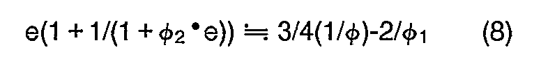
- the interval between principal points of a composite lens system consisting of the second surface and the second and the third lenses is designated by e, the condition represented by the following expression can be obtained:
- the pupil of the composite lens system consisting of the second surface, the second lens and the third lens is required to coincide with the focal point of the first surface. Accordingly, the condition represented by the following expression can be obtained:
- the objective lens system is required to satisfy the inequalities (12A) and (12B).
- Fig. 12 is a block diagram of an objective lens system according to a preferred example of the second embodiment.
- an objective lens system 50 includes a first to a third lenses 51 to 53.
- the lenses 51 to 53 are serially arranged in that order from an object side (left-hand side of the figure) to an image side (right-hand side of the figure) with predetermined air spaces therebetween.
- the first and the third lenses 51 and 53 have a positive power, whereas the second lens 52 have a negative power.
- the first lens 51 has a convex surface 51 a which is directed toward the object side.
- the following table 6 shows lens data of the objective lens system 50:
- the symbol r represents radius of curvature of an i-th lens surface from the object side (left-hand side in the figure), and the symbol d; represents a distance between an i-th lens surface and an (i + 1 )-th lens surface along an optical axis Z, where the subscript i is an integer from one to six.
- the first and the second lenses 51 and 52 are all made of quartz, while the third lens 53 is made of fluorite.
- the focal length f of the objective lens system 50 is 60, the numerical aperture (NA) thereof is 1/24, and the image size thereof is 10.6.
- the power ⁇ 1 + of the convex surface 51 a of the first lens 51 and the power ⁇ 1- of a surface 51 b of the first lens 51 which is directed to the image side are respectively as follows:
- the powers 412 and ⁇ 3 of the second and the third lenses 52 and 53, the power ⁇ 23 of the composite lens system consisting of the second lens 52 and the third lens 53, and the power ⁇ of the entire system are:
- the objective lens system 50 is an infinity corrected objective system and acts in combination with the image formation lens system 150.
- the equation below gives the imaging magnification M of a microscope utilizing the image formation lens system 150 and the objective lens system 50.
- Figs. 13A and 13B illustrate spherical aberration and sine condition, respectively, in the optical system utilizing the objective lens system 50 and the image formation lens system 150, while Figs. 13C and 13D showing astigmatism and distortion at light of a wavelength of 298.06 nm, respectively.
- Figs. 13A and 13B serious aberrations at ultraviolet and far ultraviolet light do not occur in the objective lens system 50.
- the objective lens system 50 is obviously employable in ultraviolet and far ultraviolet range.
- astigmatism and distortion are restrained in the optical system in which the objective lens system 50 is used (according to Figs. 13C and 13D).
- Fig. 14 is a block diagram of an objective lens system according to another example of the second embodiment.
- An objective lens system 60 is basically identical to the objective lens system 50 in structure. That is, the objective lens system 60 includes a first to a third lenses 61 to 63, the first to the third lenses 61 to 63 being serially disposed in that order from an object side (left-hand side of the figure) to an image formation side (right-hand side of the figure) with predetermined air spaces therebetween.
- the second lens 62 is made of quartz, while the first and the third lens 61 and 63 are all made of fluorite.
- the focal length f of the objective lens system 60 is 60, the numerical aperture (NA) thereof is 1/24, and the image size thereof is 10.6.
- the power ⁇ 1 + of a convex surface 61 a of the first lens 61 and the power ⁇ 1- of a surface 61 b of the first lens 61 which is directed to the image side are respectively as follows:
- the powers ⁇ 2 and ⁇ 3 consisting of the second and the third lenses 62 and 63
- the power ⁇ of the entire system (the objective lens system 60) are respectively as follows:
- the objective lens system 60 is an infinity corrected objective system and acts in combination with the image formation lens system 150. Hence, the equation below gives the imaging magnification M of a microscope utilizing the image formation lens system 150 and the objective lens system 60.
- Figs. 15A and 15B illustrate spherical aberration and sine condition, respectively, in the optical system utilizing the objective lens system 60 and the image formation lens system 150, while Figs. 15C and 15D showing astigmatism and distortion at light of a wavelength of 298.06 nm, respectively.
- Figs. 15A and 15B serious aberrations at ultraviolet and far ultraviolet light do not occur in the objective lens system 60.
- the objective lens system 60 is obviously employable in ultraviolet and far ultraviolet range.
- astigmatism and distortion are restrained in the optical system in which the objective lens system 60 is used (according to Figs. 15C and 15D).
- the objective lens systems 50 and 60 according to the second embodiment are all employable in ultraviolet and/or far ultraviolet range and display excellent properties at light of these ranges. Moreover, in the objective lens systems of the second embodiment, the first to the third lenses are separated from each other. This eliminates optical contact between the lenses, and hence would successfully lead to cost reduction.
- the objective lens systems 50 and 60 are employable in a very wide range, i.e., from infrared to far ultraviolet.
- the objective lens system 160 (Fig. 2) is combined with the image formation lens system 150, thereby to obtain the imaging magnification M of -10. More precisely, the focal length of the objective lens system 160 is 30, whereas the focal length of any of the objective lens systems 50 and 60 is 60. Hence, the imaging magnification M can be varied from -10 to -5 by replacing, for instance, the objective lens system 160 with the objective lens system 50 of the second embodiment while fixing the image formation lens system 150 in the same position.
- Each of the objective lens systems 50 and 60 has a parfocal relation with respect to the objective lens system 160 as set forth. This eliminates time consuming process of bringing the microscope into focus after replacement (for example, after the objective lens system 10 has replaced the objective lens system 160), whereby operation of the microscope would be greatly improved.
- the objective lens systems 50 and 60 have a pupil diameter of which roughly coincides with the pupil of the objective lens system 160. In consequence, the replacement accompanies only negligible changes in quantity of illumination light onto an object, promising fairy good observation.
- An objective lens system includes a first to a third lens groups disposed in that order from an object side to an image formation side with predetermined air spacings therebetween.
- the first lens group includes a lens which is made of either quartz or fluorite and which has a positive power.
- the second lens group includes a lens which is made of quartz and which has a negative power.
- the third lens group includes a lens pair or two lens pairs spaced apart from each other. Each lens pair consists of a negative lens made of quartz and a positive lens made of fluorite, the lenses being apart from each other.
- light in the ultraviolet or far ultraviolet region can transmit the objective lens system.
- the objective lens system is useful in the ultraviolet and far ultraviolet regions.
- the respective lenses are separated from each other at predetermined air intervals. Therefore, the optical contact is not required and the objective lens system can be provided at low cost.
- the third lens group is provided with the lens pair which consists of the positive lens made of fluorite and the negative lens made of quartz. This allows various aberrations such as spherical aberration and chromatic aberration to correct.
- the objective lens system according to the third embodiment is interchangeable with other objective lens system, according to the precedent applications, for forming an image by cooperating with an image formation lens system.
- correction of chromatic aberration is carried out through the third lens group consisting of the positive lens and the negative lens.
- the second lens group having the large negative power is provided between the first and the third lens groups so that the objective lens system is a so-called telephoto type lens system.
- the focal length of the objective lens system grows larger compared to the total length thereof.
- the first lens group having the positive power is provided so that the objective lens system has a telecentric characteristic on the object side.
- a composite lens system consisting of the second and the third lens groups has a large focal length and functions as a teleconverter of the first lens group. That is, the composite lens system magnifies the focal length of the first lens group to adjust the focal length of the objective lens system to a desired value.
- ⁇ 1 , ⁇ 2 and ⁇ 3 are powers of the first to the third lens groups, respectively, and is a power of the entire system.
- the composite lens system need not be a complete afocal system, but is only required to satisfy the following inequalities (16A) and (16B):
- is preferably set within the range of 1.3 to 1.4 in consideration of the dispersion of fluorite and quartz, where ⁇ +, ⁇ - are powers of the positive and the negative lenses of the third lens group, respectively.
- the objective lens system includes the first to the third lens groups, it is rather preferable that the aberration caused by the first and the second lens groups is corrected through the third lens group.
- the objective lens system must satisfy the following inequality (18): where where e12 2 is an interval between principal points of a lens system consisting of the first and the second lens goups.
- e12 2 is an interval between principal points of a lens system consisting of the first and the second lens goups.
- the focal point of the objective lens system on the image side is located substantially in the third lens group so that the parfocal length is 0.3 times the focal length of the objective lens system.
- the condition represented by the following expression can be obtained:
- the pupil of the composite lens system consisting of the second and the third lens groups is required to coincide with the focal point of the first lens group. Accordingly, the condition represented by the following expression can be obtained:
- the objective lens system is required to satisfy the inequality (18).
- Fig. 16 is a block diagram of an objective lens system according to a preferred example of the third embodiment.
- an objective lens system 70 includes a first to a third lens groups LG 1 to LG 3 .
- the first to the third lens groups LG 1 to LG 3 are arranged at predetermined air intervals serially from an object side (left-hand side of the figure) to an image side (right-hand side of the figure).
- the first lens group LG 1 includes a lens 71 having a positive power
- the second lens group LG 2 includes a lens 72 having a negative power.
- the third lens group LG 3 includes two lens pairs LP 1 and LP 2 arranged at a predetermined air interval.
- a lens 73 having a negative power and a lens 74 having a positive power are arranged at a predetermined air interval serially from the object side to the image side.
- a negative lens 75 and a positive lens 76 are arranged at a predetermined air interval serially from the object side to the image side.
- the following table 8 shows lens data of the objective lens system 70:
- the symbol r i represents radius of curvature of an i-th lens surface from the object side (left-hand side in the figure)
- the symbol d j represents a distance between an i-th lens surface and an (i + 1 )-th lens surface along an optical axis Z, where the subscript i is an integer from one to twelve.
- the lenses 72, 73 and 75 are made of quartz, whereas the lenses 71, 74 and 76 are made of fluorite.
- the focal length f of the objective lens system 70 is 150, the numerical aperture (NA) thereof is 1/60, and the image size thereof is 10.6.
- powers ⁇ 1 , ⁇ 2 and ⁇ 3 of the first to third lens groups LG1, LG 2 and LG 3 , and a power ⁇ of the entire system are respectively as follows:
- Powers ⁇ -1, and ⁇ +1 of the lenses 73 and 74 and powers 0- 2 and ⁇ +2 of the lenses 75 and 76 are as follows:
- An interval e 12 between principal points of a lens system consisting of the first and the second lens groups LG 1 and LG 2 is as follows:
- the objective lens system 70 is an infinity corrected objective system and acts in combination with the image formation lens system 150. Hence, the equation below gives the imaging magnification M of a microscope utilizing the image formation lens system 150 and the objective lens system 70.
- Figs. 17A and 17B illustrate spherical aberration and sine condition, respectively, in the optical system utilizing the objective lens system 70 and the image formation lens system 150, while Figs. 17C and 17D showing astigmatism and distortion at light of a wavelength of 298.06 nm, respectively.
- Figs. 17A and 17B serious aberrations at ultraviolet and far ultraviolet light do not occur in the objective lens system 70.
- the objective lens system 70 is obviously employable in ultraviolet and far ultraviolet range.
- astigmatism and distortion are restrained in the optical system in which the objective lens system 70 is used (according to Figs. 17C and 17D).
- Fig. 18 is a block diagram of an objective lens system according to another example of the third embodiment.
- An objective lens system 80 according to the second preferred embodiment is basically similar to the objective lens system 70 in structure, except that the third lens group LG 3 is composed of one lens pair LP 1 in the eighth example.
- the following table 9 shows lens data of the objective lens system 80: As will be understood from Table 9, the lenses 82 and 83 are made of quartz, where the lenses 81 and 84 are made of fluorite.
- the focal length f of the objective lens system 80 is 150, the numerical aperture (NA) thereof is 1/60, and the image size thereof is 10.6.
- powers ⁇ 1 , ⁇ 2 and ⁇ 3 of the first to the third lens groups LG 1 , LG 2 and LG 3 , and a power ⁇ of the entire system are respectively as follows:
- Powers ⁇ - and ⁇ + of the lenses 83 and 84 are as follows:
- An interval e l2 between principal points of a lens system consisting of the first and the second lens groups LG 1 and LG 2 is as follows:
- the objective lens system 80 is an infinity corrected objective system and acts in combination with the image formation lens system 150. Hence, the equation below gives the imaging magnification M of a microscope utilizing the image formation lens system 150 and the objective lens system 80.
- Figs. 19A and 19B illustrate spherical aberration and sine condition, respectively, in the optical system utilizing the objective lens system 80 and the image formation lens system 150, while Figs. 19C and 19D showing astigmatism and distortion at light of a wavelength of 298.06 nm, respectively.
- Figs. 19A and 19B serious aberrations at ultraviolet and far ultraviolet light do not occur in the objective lens system 80.
- the objective lens system 80 is obviously employable in ultraviolet and far ultraviolet range.
- astigmatism and distortion are restrained in the optical system in which the objective lens system 80 is used (according to Figs. 19C and 19D).
- Fig. 20 is a block diagram of an objective lens system according to another example of the third embodiment.
- An objective lens system 90 is identical to the objective lens system 80 in structure.
- Table 10 shows lens data of the objective lens system 90:
- the lenses 91 to 93 are made of quartz and the lens 94 is made of fluorite.
- the focal length f of the objective lens system 90 is 150, the numerical aperture (NA) thereof is 1/60, and the image size thereof is 10.6.
- powers ⁇ 1 , ⁇ 2 and ⁇ 3 of the first to the third lens groups LG 1 , LG 2 and LG 3 , and a power ⁇ of the entire system are respectively as follows:
- Powers ⁇ - and ⁇ + of the lenses 93 and 94 are as follows:
- An interval e 12 between principal points of a lens system consisting of the first and the second lens groups LG 1 and LG 2 is as follows:
- the objective lens system 90 satisfies the inequality (17). In addition, it is also obvious that the objective lens system 90 satisfies the inequality (18).
- the objective lens system 90 is an infinity corrected objective system and acts in combination with the image formation lens system 150.
- the equation below gives the imaging magnification M of a microscope utilizing the image formation lens system 150 and the objective lens system 90.
- Figs. 21 A and 21 B illustrate spherical aberration and sine condition, respectively, in the optical system utilizing the objective lens system 90 and the image formation lens system 150, while Figs. 21 C and 21 D showing astigmatism and distortion at light of a wavelength of 298.06 nm, respectively.
- Figs. 21 A and 21 B serious aberrations at ultraviolet and far ultraviolet light do not occur in the objective lens system 90.
- the objective lens system 90 is obviously employable in ultraviolet and far ultraviolet range.
- astigmatism and distortion are restrained in the optical system in which the objective lens system 90 is used (according to Figs. 21 C and 21 D).
- the objective lens systems 70, 80 and 90 according to the third embodiment are all employable in ultraviolet and/or far ultraviolet range and display excellent properties at light of these ranges. Moreover, in the objective lens systems of the third embodiment, the lenses of the objective lens system are separated from each other. This eliminates optical contact between the lenses, and hence would successfully lead to cost reduction.
- the objective lens systems 70, 80 and 90 are employable in a very wide range, i.e., from infrared to far ultraviolet.
- the objective lens system 160 (Fig. 2) is combined with the image formation lens system 150, thereby to obtain the imaging magnification M of -10. More precisely, the focal length of the objective lens system 160 is 30, whereas the focal length of any of the objective lens systems 70, 80 and 90 is 150. Hence, the imaging magnification M can be varied from -10 to -2 by replacing, for instance, the objective lens system 160 with the objective lens system 70 of the third embodiment while fixing the image formation lens system 150 in the same position.
- Each of the objective lens systems 70, 80 and 90 has a parfocal relation with respect to the objective lens system 160 as set forth. This eliminates time consuming process of bringing the microscope into focus after replacement (for example, after the objective lens system 70 has replaced the objective lens system 160), whereby operation of the microscope would be greatly improved.
- the objective lens systems 70, 80 and 90 have a pupil diameter of which roughly coincides with the pupil of the objective lens system 160. In consequence, the replacement accompanies only negligible changes in quantity of illumination light onto an object, promising fairy good observation.
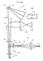
- Fig. 22 is a schematic block diagram of a system 102 for measuring film thickness.
- the system 102 includes a microspectroscope 101 for detecting spectrum of a sample to be measured and an arithmetic unit 103 for calculating the film thickness of the measured sample S on the basis of spectral data obtained by the microspectroscope 101.
- the microspectroscope 101 includes an illuminating optical system 110, a microscopic optical system 120, a reflecting mirror 130, a spectroscopic unit 140, and a monitoring optical system 145.
- the illuminating optical system 110 includes a light source 111 for projecting light which includes ultraviolet and far ultraviolet rays, a condenser lens 112, an aperture stop 113, a field stop 114 and another condenser lens 115.
- a light source 111 for projecting light which includes ultraviolet and far ultraviolet rays
- a condenser lens 112 for projecting light which includes ultraviolet and far ultraviolet rays
- an aperture stop 113 illuminating light from the light source 111
- the field stop 114 includes illuminating light from the light source 111
- another condenser lens 115 includes illuminating light from the light source 111 to the microscopic optical system 120 through the condenser lens 112, the aperture stop 113, the field stop 114 and the condenser lens 115.
- the microscopic optical system 120 includes an objective lens system 121 which is identical to that shown in Fig. 3, an image formation lens system 124 which is identical to that shown in Fig. 4 and a beam splitter 123 provided between the objective lens system 121 and the image formation lens system 124.
- Symbol 122 denotes a pupil position of the objective lens system 121.
- the illuminating light from the light source 111 passes through the condenser lens 112, the aperture stop 113, the field stop 114 and the condenser lens 115, and is guided to the objective lens system 121 by the beam splitter 123.
- the illuminating light is through the objective lens system 121 and is applied onto the surface of a measured sample S.
- the sample S is supported by a sample holder (not shown).
- Reflected light from the surface of the measured sample S is enlarged by the lens 121 and imaged at a position close to the reflecting mirror 130, the beam splitter 123 and the image formation lens system 124.
- the reflecting mirror 130 is provided with a pinhole 131. Reflected light L s passing through the pinhole 131 enters the spectroscopic unit 140.
- the spectroscopic unit 140 is formed by a diffraction grating 141 for separating the reflected light L s into spectral components and a photo detector 142 for detecting the spectrum of the spectrally diffracted light.
- the diffraction grating 141 may be prepared by a flat field type diffraction grating which images a spectrum on a flat plane. Alternatively, the diffraction grating may have a sweeper.
- the photo detector 142 which is formed by a photodiode array or a CCD, for example, is conjugate with the pinhole 131. Alternatively, the photo detector 142 may include a photomultiplier.
- the spectroscopic unit 140 Since the spectroscopic unit 140 has the aforementioned structure, the reflected light L s is separated into its spectral components by the diffraction grating 141, and the respective spectral components are received by the photo detector 142, which in turn outputs a signal corresponding to the spectrum of the light Ls.
- the light reflected by the reflecting mirror 130 enters the monitoring optical system 145, and is imaged at an image-formation position 147 through a relay lens 146.
- an enlarged image of the surface of the sample S is imaged on an image-formation plane, so that the measuring position of the sample S can be confirmed and focusing can be performed on the basis of the enlarged image.
- Fig. 23 is a flow chart of a method of measuring film thickness.
- an operator inputs spectrum data B(X) of a sample (hereinafter referred to as "standard sample"), whose spectrum data is known, in the arithmetic unit 103 through a keyboard (not shown), to store the data in a memory (not shown) provided in the arithmetic unit 103.
- the standard sample may be prepared by a silicon substrate, a substrate which is deposited with aluminum on its surface, or the like.
- step S1 the operator sets the standard sample on the sample holder of the microspectroscope 101 (step S1), and supplies a command for detecting calibration data to the arithmetic unit 103.
- the microspectroscope 101 detects the spectrum of the standard sample, to store data B'(X) relating to the spectrum in the memory of the arithmetic unit 103 (step S2).
- the operator removes the standard sample from the microspectroscope 101 and sets the measured sample S on the sample holder (step S3). Thereafter, the operator supplies a command to the arithmetic unit 103 to start measurement, so that the microspectroscope 101 detects the spectrum of the measured sample S in response to a command from the arithmetic unit 103, to store data S'(X) relating to the spectrum thereof in the memory of the arithmetic unit 103 (step S4).
- step S5 The data S'(X), B(X) and B'(X) stored in the memory are read (step S5) into the arithmetic unit 103, to obtain data S(X) in accordance with the following expression:
- the data S( ⁇ ) corresponds to a signal from the microspectroscope 101 on the assumption that absolutely no influence is caused by the factors such as spectral transmittance characteristics of the illuminating optical system 110 and the microscopic optical system 120.
- the data S(X) shows the true spectrum of the measured sample S.
- the arithmetic unit 103 calculates the thickness of the thin film (step S6).
- the principle of calculates film thickness is well known in the art, and hence description thereof is omitted.
- the data S'(X) relating to the actually measured spectrum is calibrated in the aforementioned manner to obtain the data S(X) relating to the true spectrum, whereby the film thickness can be accurately measured.
- the present invention can be employed within the restricted to use within a system for measuring film thickness.
- the invention has general applications as an objective lens optical system.
Landscapes
- Physics & Mathematics (AREA)
- General Physics & Mathematics (AREA)
- Optics & Photonics (AREA)
- Chemical & Material Sciences (AREA)
- Health & Medical Sciences (AREA)
- Toxicology (AREA)
- Crystallography & Structural Chemistry (AREA)
- Analytical Chemistry (AREA)
- Lenses (AREA)
Abstract
Description
- The present invention relates to an objective lens system for use within a microscope which is employable in ultraviolet range, in particular, in far ultraviolet range, in which light has a wavelength of shorter than 300 nm. Description of the Prior Art
- It is commonly known in the art that a microscope has a property that, assuming numerical aperture (NA) of an objective lens system used within microscope remains constant, the shorter a wavelength of light used therein, the better its resolution limit. Thus, it is possible to observe a sample in greater detail by shortening the wavelength of illumination light. In addition, illuminating a sample with ultraviolet light would often result in fluorecence of stronger intensity discharged from a sample than fluorecence obtained by illuminating with visible light. Against this backdrop, a microscope employable in ultraviolet range is preferred in the art, because of obtaining more information by observing a sample through such a microscope. Thus, an objective lens system for use within a microscope must be employable in ultraviolet and/or far ultraviolet range.
- Among known conventional objective lens systems which is employable in ultraviolet and/or far ultraviolet range is, for example, an objective lens system for use within a microscope described in "Hikari Gijyutsu Contact," Volume 25, Number 2, Page 137 (Feb 1987). The objective lens system is illustrated in Fig. 1.
- In Fig. 1, an
objective lens system 170 includes afirst lens 171 made of fluorite, asecond lens group 172 and athird lens group 173 disposed in that order from an object side (left-hand side of the figure) to an image formation side (right-hand side of the figure). Thesecond lens group 172 includes twoconvex lenses second lens group 172 is formed by holding the concave lens 172a between theconvex lenses third lens group 173 is formed, in a similar manner to thesecond lens group 172, by holding a concave lens 173a made of quartz between twoconvex lenses - Since the
lenses 171, 172a to 172c and 173a to 173c are made of either quartz or fluorite, theobjective lens system 170 is capable of transmitting ultraviolet and/or far ultraviolet light, and hence, employable in ultraviolet and/or far ultraviolet range. - In addition to this, chromatic aberration can be corrected in the
objective lens system 170, since thesecond lens group 172 is composed of the concave lens 172a made of quartz and theconvex lenses third lens group 173 is composed of the concave lens 173a made of quartz and theconvex lenses - The
convex lens 172b, the concave lens 172a and theconvex lens 172c of thesecond lens group 172 are brought into optical contact and joined to each other. Similarly in thethird lens group 173, theconvex lens 173b, the concave lens 173a and theconvex lens 173c are brought into optical contact thereby to be joined to each other. This is attributable to the current technical level that adhesive which transmits far ultraviolet light is not available yet. Further, when a junction surface between lenses has to completely eliminate reflection thereat, there is no option other than cementing by optical contact. Thus, in the process of manufacturing theobjective lens system 170, junction surfaces must be finished with extremely high accuracy, which would result in largely increased cost. - The inventor of the present invention has already suggested an objective lens system for use within a microscope in which such a problem is solved. See Japanese Patent Laid-Open Gazette Nos. 1-319719 and 1-319720. These literature references will be hereinafter referred to as the "precedent applications." Fig. 2 shows an objective lens system for use within a microscope, namely,
objective lens system 160, according to an embodiment of the precedent applications. The suggestedobjective 160 includeslenses 161 to 163, which are made of either quartz or fluorite. Thelenses 161 to 163, i.e., a first to a third lenses, are displaced in that order from an object side (left-hand side in the figure) to an image formation side (right-hand side in the figure) with preselected air spaces therebetween. This enables theobjective lens system 160 to be employable in both ultraviolet and far ultraviolet range. Thelenses 161 to 163, as just has been mentioned, are separated from each other; that is, theobjective lens system 160 includes no junction surfaces. Thus, including no optical contact, theobjective lens system 160 is free from the problem relating to manufacture cost. - The
objective lens system 160 cooperates with an image formation lens system (detailed structure thereof will be given later) in order to form an image of an object to be observed on the focal plane of the image formation lens system at a predetermined imaging magnification M. The imaging magnification M is a ratio of the focal length f2 of the image formation lens system to the focal length f1 of theobjective lens system 160, and is given as:
- In general, an objective lens system is replaced with other one while an image formation lens system is fixed, whereby the imaging magnification M is changed. Objective lens systems for replacement are necessary for this end, each of the lens systems having a focal length different from the focal length f1.
- The equation (1) gives that an objective lens system for replacement which has a focal length of 2 ° f1 is necessary to halve the imaging magnification M. If being required here is nothing more than to form the other objective lens system for replacement such that its focal length becomes 2'fi, the demanded objective lens system for replacement merely has to have a size of a proportionally enlarged
objective lens system 160. - However, if the
objective lens system 160 is replaced with the demanded objective lens system for replacement mentioned above (which is equal to theobjective lens system 160 doubled in terms of size), a distance between the demanded objective lens system for replacement and the object to be observed would have to be also doubled as long as a pupil of a microscope fixed. This is extremely time-consuming as well as labor-consuming in that the microscope must be brought into focus once again all from the beginning after the replacement, and therefore, would enormously deteriorate operation of the microscope. In addition, such replacement causes doubling of the pupil size, which in turn causes remarkable change in quantity of illumination light onto the object. On the other hand, if the position of the object is fixed, the position of the pupil would be moved. This should also be avoided in an illumination system for illuminating the object, since positional changes of the pupil exerts unfavorable affect upon illumination condition. - Thus, when imaging magnification is to be halved by replacing objective lens systems, an objective lens system for replacement must have:
- (a) a focal length double that of the
objective lens system 160; - (b) parfocality; that is, a property of eliminating the necessity of bringing a microscope into focus once again after replacement; and
- (c) a pupil which is roughly the same in size with that of the
objective lens system 160. - The equation (1) also gives that an objective lens system for replacement which has a focal length of SOf1 is necessary to observe an object at an imaging magnification of M/5. Thus, in the case of obtaining an image of the object under a microscope at M/5 power, an objective lens system for replacement must have:
- (a) a focal length being five times larger than that of the
objective lens system 160; - (b) parfocality; that is, a property of eliminating the necessity of bringing a microscope into focus once again after replacement; and
- (c) a pupil which is roughly the same in size with that of the
objective lens system 160. - The present invention is directed to an objective lens system for use within a microscope. The system includes: a first lens made of either quartz or fluorite, the first lens having a positive power; a second and a third lenses made of quartz, both of the second and third lenses having a negative power; and a fourth lens made of fluorite, the fourth lens having a positive power, wherein the first to the fourth lenses are disposed in that order from an object side to an image formation side with predetermined air spacings therebetween.
- The present invention is also directed to an objective lens system. The system includes: a first lens being a meniscus lens made of either quartz or fluorite, the first lens having a positive power, the first lens having a convex surface directed toward an object; a second lens made of quartz, the second lens having a negative power; and a third lens made of fluorite, the third lens having a positive power, wherein the first to the third lenses are disposed in that order from an object side to an image formation side with predetermined air spacings therebetween.
- The present invention is also directed to an objective lens system. The system includes: a first lens group including a lens made of either quartz or fluorite, the lens having a positive power; a second lens group including a lens made of quartz, the lens having a negative power; and a third lens group including a lens pair, the lens pair comprising a lens having a positive power and a lens having a negative power, the positive lens made of fluorite, the negative lens made of quartz, the positive and negative lenses being separated from each other, wherein the first to third lens groups are disposed in that order from an object side to an image formation side with predetermined air spacings therebetween.
- The present invention also relates to an apparatus for measuring the thickness of a film on a sample, the apparatus including: means for illuminating a sample, and a microscopic optical system for imaging ultraviolet and/or far ultraviolet light from the sample, the microscopic optical system including an objective lens system for converging the light in an image formation direction.
- An object of the present invention is to provide an inexpensive objective lens system for use within a microscope which is employable in ultraviolet and/or far ultraviolet range and which is different in structure from the objective lens system according to the precedent applications.
- Another object of the present invention is to provide an objective lens system for use within a microscope which has a focal length approximately half, parfocality, and a pupil roughly the same as those of the objective lens system of the precedent applications which forms an image on an image plane of an image formation lens system at a predetermined imaging magnification when cooperates with the image formation lens system.
- Another object of the present invention is to provide an apparatus which uses ultraviolet and/or far ultraviolet light to accurately measure the thickness of a film which is formed on a sample.
- These and other objects, features, aspects and advantages of the present invention will become more apparent from the following detailed description of the present invention when taken in conjunction with the accompanying drawings.
-
- Figs. 1 and 2 are a block diagram of a conventional objective lens system for use within a microscope;
- Figs. 3, 6, 8 and 10 are a block diagrams of an objective lens system according to a first embodiment of the present invention;
- Fig. 4 is a block diagram of an image formation lens system;
- Figs. 5A, 5B, 5C and 5D illustrate spherical aberration, sine condition, astigmatism and distortion of an optical system utilizing the image formation lens system of Fig. 4 and the objective lens system of Fig. 3, respectively;
- Figs. 7A, 7B, 7C and 7D illustrate spherical aberration, sine condition, astigmatism and distortion of an optical system utilizing the image formation lens system of Fig. 4 and the objective lens system of Fig. 6, respectively;
- Figs. 9A, 9B, 9C and 9D illustrate spherical aberration, sine condition, astigmatism and distortion of an optical system utilizing the image formation lens system of Fig. 4 and the objective lens system of Fig. 8, respectively;
- Figs. 11 A, 11 B, 11 C and 11 D illustrate spherical aberration, sine condition, astigmatism and distortion of an optical system utilizing the image formation lens system of Fig. 4 and the objective lens system of Fig. 10, respectively;
- Figs. 12 and 14 are a block diagram of an objective lens system according to a second embodiments of the present invention;
- Figs. 13A, 13B, 13C and 13D illustrate spherical aberration, sine condition, astigmatism and distortion of an optical system utilizing the image formation lens system of Fig. 4 and the objective lens system of Fig. 12, respectively;
- Figs. 15A, 15B, 15C and 15D illustrate spherical aberration, sine condition, astigmatism and distortion of an optical system utilizing the image formation lens system of Fig. 4 and the objective lens system of Fig. 14, respectively;
- Figs. 16, 18 and 20 are a block diagram of an objective lens system according to a third embodiment of the present invention;
- Figs. 17A, 17B, 17C and 17D illustrate spherical aberration, sine condition, astigmatism and distortion of an optical system utilizing the image formation lens system of Fig. 4 and the objective lens system of Fig. 16, respectively;
- Figs. 19A, 19B, 19C and 19D illustrate spherical aberration, sine condition, astigmatism and distortion of an optical system utilizing the image formation lens system of Fig. 4 and the objective lens system of Fig. 18, respectively;
- Figs. 21A, 21 B, 21C and 21 D illustrate spherical aberration, sine condition, astigmatism and distortion of an optical system utilizing the image formation lens system of Fig. 4 and the objective lens system of Fig. 20, respectively;
- Fig. 22 is a schematic block diagram of a system for measuring film thickness; and
- Fig. 23 is a flow chart showing a method of measuring film thickness by the system of Fig. 22.
- An objective lens system according to a first embodiment of the present invention includes a first to a fourth lenses disposed in that order from an object side to an image formation side with predetermined air spacings therebetween. The first lens is made of either quartz or fluorite, and has a positive power. The second and the third lenses are made of quartz, and have a negative power. The fourth lens is made of fluorite, and has a positive power. This enables the objective lens system to transmit ultraviolet and/or far ultraviolet light, and hence to be employed in ultraviolet and/or far ultraviolet range.
- In addition to this, the first to the fourth lenses are separated from each other by a predetermined air space; that is, the objective lens system needs no optical contact. This enables large reduction in cost for the objective lens system.
- Further, the first and the fourth lenses have a positive power, whereas the second and the third lenses have a negative power. This enables corrections of aberrations such as spherical and chromatic aberrations.
- Aberrations can be further moderated especially when the objective lens system satisfies the following inequities:


- This is firstly because aberrations are excessively corrected (i.e., overcorrected) when an absolute value |φ1,/φ2| is not more than 0.54, whereas aberrations can not be corrected inadequately (i.e., undercorrected) when the value not less than 0.75.
- Further, when an absolute value |φ4/φ3| is not more than 0.9, aberrations are excessively corrected (i.e., overcorrected), whereas aberrations are inadequately corrected (undercorrected) when the value not less 0.95.
- The objective lens system according to the first embodiment is interchangeable with other objective lens system, according to the precedent applications, for forming an image by cooperating with an image formation lens system. In the objective lens system of the first embodiment, the third lens having the negative power and the fourth lens having the positive power are provided, resulting of correction for chromatic aberration. The second lens has the large negative power, so that the objective lens system is a so-called telephoto type lens system. Thus, the focal length of the objective lens system grows larger compared to the total length thereof.
- The first lens has the positive power, allowing the objective lens system to have a telecentric characteristic on the object side.
- The composite lens system consisting of the second to the fourth lenses has a large focal length and functions as a teleconverter for the first lens. That is, the composite lens system magnifies the focal length of the first lens so as to adjust the focal length of the objective lens system to a desired value.
- For satisfying this condition accurately, the following equation must be satisfied:


- As above-mentioned, the correction of the chromatic aberration is carried out by the combination of the third and fourth lenses. In the case of forming the image of the object through the third and the fourth lenses, the value |φ4/φ3| is preferably set within the range of 1.3 to 1.4 in consideration of the dispersion of fluorite and quartz. When the objective lens system includes the first to the fourth lenses, however, it is rather preferable to design the objective lens system so that a composite lens system consisting of the third and the fourth lenses excessively corrects the aberration, the reason being for the correction of the aberration caused by the first and second lenses. Hence, it is preferable to set the value |φ4/φ3| within the range of 0.90 to 0.95; that is, to set the objective lens system to satisfy the inequality (3).
- Furthermore, in order to give parfocality to the objective lens system of the first embodiment, the following inequality must be satisfied:


- For providing the objective lens system with the telecentric characteristic on the object side, the pupil of the composite lens system consisting of the second to the fourth lenses must be provided at the focal point of the first lens. Accordingly, the condition represented by the following expression can be obtained:
- Fig. 3 is a block diagram of an objective lens system according to a preferred example of the first embodiment. In Fig. 3, an
objective lens system 10 includes a first to afourth lenses 11 to 14. Thelenses 11 to 14 are serially arranged in that order from an object side (left-hand side of the figure) to an image side (right-hand side of the figure) with predetermined air spaces therebetween. The first and thefourth lenses third lenses - The following table 1 shows lens data of the objective lens system 10:

third lenses 11 to 13 are all made of quartz, while the fourth lens is made of fluorite. - The focal length f of the
objective lens system 10 is 60, the numerical aperture (NA) thereof is 1/24, and the image size thereof is 10.6. - With respect to the wavelength of 298.06 (nm), the powers φ1, φ2, φ3 and 04 of the first to the
fourth lenses 11 to 14, the power φ34 of the composite lens system consisting of thethird lens 13 and thefourth lens 14, and the power φ of the entire system (the objective lens system 10) are as follows:


- Thus,


- It is obvious that the
objective lens system 10 satisfies the inequalities (2) and (3). Further,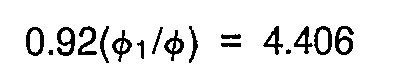


- It is also obvious that the
objective lens system 10 satisfies the inequalities (5A) and (5B). In addition,


objective lens system 10 satisfies the inequalities (6A) and (6B). - The
objective lens system 10 is designed as a so-called infinity corrected objective system so as to be in use within a reflecting type microscope. That is, theobjective lens system 10, when used in combination with an image formation lens system, forms an image of an object on the focal plane of the image formation lens system. The image formation lens system is described in the following: - Fig. 4 is a block diagram of the image formation lens system, the image formation lens system being identical to the one disclosed in the precedent applications, namely, Japanese Patent Laid-Open Gazette Nos. 1-319719 and 1-319720. In Fig. 4, an image
formation lens system 150 includes a first to athird lenses 151 to 153. The first, the second and thethird lenses - Table 2 below shows data of the image
formation lens system 150.
first lens 151 is made of fluorite, the second and thethird lenses formation lens system 150 is 300. - Hence, the equation below gives the imaging magnification M of a microscope utilizing the image
formation lens system 150 and theobjective lens system 10.
- Figs. 5A and 5B illustrate spherical aberration and sine condition, respectively, caused in the optical system formed by the image
formation lens system 150 and theobjective lens system 10. In Figs. 5A and 5B (and also in Figs. 7A, 7B, 9A, 9B, 11A, 11B, 13A, 13B, 15A, 15B, 17A, 17B, 19A, 19B, 21A and 21 B: provided later), alphabetic characters A, B, C and D show a value with respect to light of wavelengths of 298.06 nm, 202.54 nm, 398.84 nm and 253.70 nm, respectively. - Figs. 5C and 5D illustrate astigmatism and distortion at light of a wavelength of 298.06 nm, respectively. In Fig. 5C (and in Figs. 7C, 9C, 11C, 13C, 15C, 17C, 19C and 21 C), a solid line S relates to the sagittal image field while the broken line M to the meridional image field.
- Figs. 5A and 5B clearly show that the
objective lens system 10 successfully restrains aberrations at ultraviolet and far ultraviolet light. Thus, theobjective lens system 10 is employable in ultraviolet and far ultraviolet range. In addition, Figs. 5C and 5D show that serious astigmatism and distortion do not occur in the optical system utilizing theobjective lens system 10. - Fig. 6 is a block diagram of an objective lens system according to another example of the first embodiment. An
objective lens system 20 is basically identical to theobjective lens system 10 in structure. That is, theobjective lens system 20 includes a first to afourth lenses 21 to 24, the first to the fourth lenses being serially disposed in that order from an object side (left-hand side of the figure) to an image formation side (right-hand side of the figure) with predetermined air spaces therebetween. - Data of the
objective lens system 20 are available from Table 3.
- As will be understood from Table 3, the first to the
third lenses 21 to 23 are all made of quartz, while thefourth lens 24 is made of fluorite. - The focal length f of the
objective lens system 20 is 60, the numerical aperture (NA) thereof is 1/24, and the image size thereof is 10.6. - With respect to the wavelength of 298.06 (nm), the powers φ1, φ2, φ3 and φ4 of the first to
fourth lenses 21 to 24, the power φ34 of the composite lens system consisting of thethird lens 23 and thefourth lens 24, and the power φ of the entire system (the objective lens system 20) are respectively as follows:


- Thus,


- It is obvious that the
objective lens system 20 satisfies the inequalities (2) and (3). Further,


- It is also obvious that the
objective lens system 20 satisfies the inequalities (5A) and (5B). In addition,


- It is also obvious that the
objective lens system 20 satisfies the inequalities (6A) and (6B). - The
objective lens system 20 is an infinity corrected objective system, similarly to theobjective lens system 10, and acts in combination with the imageformation lens system 150. Hence, the equation below gives the imaging magnification M of a microscope utilizing the imageformation lens system 150 and theobjective lens system 20.
- Figs. 7A and 7B illustrate spherical aberration and sine condition, respectively, in the optical system utilizing the
objective lens system 20 and the imageformation lens system 150, while Figs. 7C and 7D showing astigmatism and distortion at light of a wavelength of 298.06 nm, respectively. - According to Figs. 7A and 7B, serious aberrations at ultraviolet and far ultraviolet light do not occur in the
objective lens system 20. Thus, theobjective lens system 20 is obviously employable in ultraviolet and far ultraviolet range. In addition, astigmatism and distortion are restrained in the optical system in which theobjective lens system 20 is used (according to Figs. 7C and 7D). - Fig. 8 is a block diagram of an objective lens system according to further example of the first embodiment. An
objective lens system 30 is basically identical to theobjective lens system 10 in structure. That is, theobjective lens system 30 includes a first to afourth lenses 31 to 34, the first to the fourth lenses being serially disposed in that order from an object side (left-hand side of the figure) to an image formation side (right-hand side of the figure) with predetermined air spaces therebetween. - Data of the
objective lens system 30 are available from Table 4.
third lenses 31 to 33 are made of quartz, whereas the fourth lens 34 is made of fluorite. - The focal length f of the
objective lens system 30 is 60, the numerical aperture (NA) thereof is 1/24, and the image size thereof is 10.6. - With respect to the wavelength of 298.06 (nm), the powers φ1, φ2, 03 and φ4 of the first to the
fourth lenses 31 to 34, the power φ34 of the composite lens system consisting of thethird lens 33 and the fourth lens 34, and thepower 0 of the entire system (the objective lens system 30) are respectively as follows:


- Thus,


- It is obvious that the
objective lens system 30 satisfies the inequalities (2) and (3). Further,


- It is also obvious that the
objective lens system 30 satisfies the inequalities (5A) and (5B). In addition,

- It is also obvious that the
objective lens system 30 satisfies the inequalities (6A) and (6B). - The
objective lens system 30 is an infinity corrected objective system, similarly to theobjective lens system 10, and acts in combination with the imageformation lens system 150. Hence, the equation below gives the imaging magnification M of a microscope utilizing the imageformation lens system 150 and theobjective lens system 30.
- Figs. 9A and 9B illustrate spherical aberration and sine condition, respectively, in the optical system utilizing the
objective lens system 30 and the imageformation lens system 150, while Figs. 9C and 9D showing astigmatism and distortion at light of a wavelength of 298.06 nm, respectively. - According to Figs. 9A and 9B, serious aberrations at ultraviolet and far ultraviolet light do not occur in the
objective lens system 30. Thus, theobjective lens system 30 is obviously employable in ultraviolet and far ultraviolet range. In addition, astigmatism and distortion are restrained in the optical system in which theobjective lens system 30 is used (according to Figs. 9C and 9D). - Fig. 10 is a block diagram of an objective lens system according to further example of the first embodiment. An
objective lens system 40 is identical to theobjective lens system 10 in structure. That is, theobjective lens system 40 includes a first to afourth lenses 41 to 44, the first to the fourth lenses being serially disposed in that order from an object side (left-hand side of the figure) to an image formation side (right-hand side of the figure) with predetermined air spaces therebetween. - Data of the
objective lens system 40 are available from Table 5.
- As will be understood from Table 5, the first and the
fourth lenses third lenses 42 and 43 are made of quartz. - The focal length f of the
objective lens system 40 is 60, the numerical aperture (NA) thereof is 1/24, and the image size thereof is 10.6. - With respect to the wavelength of 298.06 (nm), the powers φ1, φ2, φ3 and φ4 of the first to the
fourth lenses 41 to 44, the power φ34. of the composite lens system consisting of the third lens 43 and thefourth lens 44, and thepower 0 of the entire system (the objective lens system 40) are respectively as follows:


- Thus,


- It is obvious that the
objective lens system 40 satisfies the inequalities (2) and (3). Further,


- It is also obvious that the
objective lens system 40 satisfies the inequalities (5A) and (5B). In addition,


- It is also obvious that the
objective lens system 40 satisfies the inequalities (6A) and (6B). - The
objective lens system 40 is an infinity corrected objective system, similarly to theobjective lens system 10, and acts in combination with the imageformation lens system 150. Hence, the equation below gives the imaging magnification M of a microscope utilizing the imageformation lens system 150 and theobjective lens system 40.
- Figs. 11 A and 11B illustrate spherical aberration and sine condition, respectively, in the optical system utilizing the
objective lens system 40 and the imageformation lens system 150, while Figs. 11 C and 11 D showing astigmatism and distortion at light of a wavelength of 298.06 nm, respectively. - According to Figs. 11 A and 11B, serious aberrations at ultraviolet and far ultraviolet light do not occur in the
objective lens system 40. Thus, theobjective lens system 40 is obviously employable in ultraviolet and far ultraviolet range. In addition, astigmatism and distortion are restrained in the optical system in which theobjective lens system 40 is used (according to Figs. 11 C and 11 D). - The
objective lens systems - Though not having especially described in the specification, it is confirmed that aberrations at visible and infrared light are also effectively restrained according to the present invention. Thus, the
objective lens systems - Now referring again to the precedent applications, the objective lens system 160 (Fig. 2) is combined with the image
formation lens system 150, thereby to obtain the imaging magnification M of -10. More precisely, the focal length of theobjective lens system 160 is 30, whereas the focal length of any of theobjective lens systems objective lens system 160 with theobjective lens system 10 of the first embodiment while fixing the imageformation lens system 150 in the same position. - Each of the
objective lens systems objective lens system 160 as set forth. This eliminates time consuming process of bringing the microscope into focus after replacement (for example, after theobjective lens system 10 has replaced the objective lens system 160), whereby operation of the microscope would be greately improved. - The
objective lens systems objective lens system 160. In consequence, the replacement accompanies only negligible changes in quantity of illumination light onto an object, promising fairy good observation. - An objective lens system according to a second embodiment of the present invention includes a first to a third lenses disposed in that order from an object side to an image formation side with predetermined air spacings therebetween. The first lens is a meniscus lens having convex surfaces directed toward an object side, and has a positive power. The second lens has a negative power, whereas the third lens has a positive power.
- The first lens is made of either quartz or fluorite, the second lens made of quartz, while the third lens made of fluorite. This enables the objective lens system of the second embodiment to transmit ultraviolet and/or far ultraviolet light, and hence to be employed in ultraviolet and/or far ultraviolet range.
- In addition to this, the first to the third lenses are separated from each other by a predetermined air space; that is, the objective lens system needs no optical contact. This enables large reduction in cost for the objective lens system.
- The objective lens system causes only negligible aberrations especially when it satisfies the following inequalities:

- The reason is that the correction of the spherical aberration is excessive when the value |φ3/φ2| is not more than 1.1 and, on the contrary, the correction of the spherical aberration is insufficient when the value |φ3/φ2| is not less than 1.3.
- The objective lens system according to the second embodiment is interchangeable with other objective lens system, according to the precede applications, for forming an image by cooperating with an image formation lens system. In the objective lens system of the second embodiment, chromatic aberration is corrected through the composite lens system consisting of the third lens having the positive power and the second lens having the negative power. A surface of the first lens on the image side (hereinafter referred to as a "second surface") has a large negative power, and thereby the objective lens system is formed into what is called a telephoto type lens system. Consequently, the focal length of the objective lens system grows larger compared to the total length thereof.
- The other surface of the first lens on the object side (hereinafter referred to as a "first surface") has a positive power, and thereby the objective lens system has a telecentric characteristic on the object side.
- The composite lens system consisting of the second surface of the first lens, the second lens and the third lens has a large focal length and functions as a teleconverter for the first surface of the first lens. That is, the composite lens system magnifies the power of the first surface to adjust the focal length of the objective lens system to a desired value.
- For satisfying this condition accurately, the following equation must be satisfied:

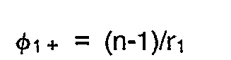

- n: refractive index of the first lens
- r1: radius of curvature of the first surface of the first lens
- r2: radius of curvature of the second surface of the first lens
- In the case of forming the image of the object through only the composite lens system consisting of the second and the third lenses, the value |φ3/φ2| is preferably set within the range of 1.3 to 1.4 in consideration of the dispersion of fluorite and quartz. When the objective lens system comprises the first to the third lenses, however, it is rather preferable to set the value so that the aberration caused by the first lens is corrected through the composite lens system. Hence, it is preferable to set the value |φ3/φ2| within the range of 1.1 to 1.3; that is, to set the objective lens system to satisfy the inequality (9).
- Furthermore, in order to give parfocality to the objective lens system of the second embodiment,the following inequalities must be satisfied:


- For providing the objective lens system with the telecentric characteristic on the object side, the pupil of the composite lens system consisting of the second surface, the second lens and the third lens is required to coincide with the focal point of the first surface. Accordingly, the condition represented by the following expression can be obtained:

- When the conditions (13) and (14) are taken into consideration, the objective lens system is required to satisfy the inequalities (12A) and (12B).
- Fig. 12 is a block diagram of an objective lens system according to a preferred example of the second embodiment. In Fig. 12, an
objective lens system 50 includes a first to athird lenses 51 to 53. Thelenses 51 to 53 are serially arranged in that order from an object side (left-hand side of the figure) to an image side (right-hand side of the figure) with predetermined air spaces therebetween. The first and thethird lenses second lens 52 have a negative power. Further, thefirst lens 51 has aconvex surface 51 a which is directed toward the object side. - The following table 6 shows lens data of the objective lens system 50:

second lenses third lens 53 is made of fluorite. - The focal length f of the
objective lens system 50 is 60, the numerical aperture (NA) thereof is 1/24, and the image size thereof is 10.6. - With respect to the wavelength of 298.06 (nm), the power φ1 + of the
convex surface 51 a of thefirst lens 51 and the power φ1- of asurface 51 b of thefirst lens 51 which is directed to the image side are respectively as follows:
third lenses second lens 52 and thethird lens 53, and the power φ of the entire system (the objective lens system 50) are: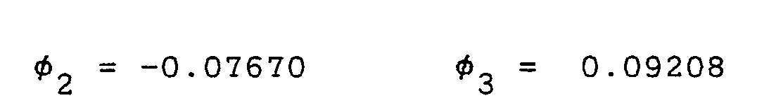

- Thus,

- It is obvious that the
objective lens system 50 satisfies the inequality (9). Further,


- It is also obvious that the
objective lens system 50 satisfies the inequalities (11 A) and (11 B). In addition,


- It is also obvious that the
objective lens system 50 satisfies the inequalities (12A) and (12B). - The
objective lens system 50 is an infinity corrected objective system and acts in combination with the imageformation lens system 150. Hence, the equation below gives the imaging magnification M of a microscope utilizing the imageformation lens system 150 and theobjective lens system 50.
- Figs. 13A and 13B illustrate spherical aberration and sine condition, respectively, in the optical system utilizing the
objective lens system 50 and the imageformation lens system 150, while Figs. 13C and 13D showing astigmatism and distortion at light of a wavelength of 298.06 nm, respectively. - According to Figs. 13A and 13B, serious aberrations at ultraviolet and far ultraviolet light do not occur in the
objective lens system 50. Thus, theobjective lens system 50 is obviously employable in ultraviolet and far ultraviolet range. In addition, astigmatism and distortion are restrained in the optical system in which theobjective lens system 50 is used (according to Figs. 13C and 13D). - Fig. 14 is a block diagram of an objective lens system according to another example of the second embodiment. An
objective lens system 60 is basically identical to theobjective lens system 50 in structure. That is, theobjective lens system 60 includes a first to athird lenses 61 to 63, the first to thethird lenses 61 to 63 being serially disposed in that order from an object side (left-hand side of the figure) to an image formation side (right-hand side of the figure) with predetermined air spaces therebetween. - Data of the
objective lens system 60 are available from Table 7.
- As will be understood from the Table 7, the
second lens 62 is made of quartz, while the first and thethird lens - The focal length f of the
objective lens system 60 is 60, the numerical aperture (NA) thereof is 1/24, and the image size thereof is 10.6. - With respect to the wavelength of 298.06 (nm), the power φ1 + of a
convex surface 61 a of thefirst lens 61 and the power φ1- of asurface 61 b of thefirst lens 61 which is directed to the image side are respectively as follows: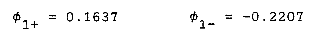
- With respect to the wavelength of 298.06 (nm), the powers φ2 and φ3 consisting of the second and the
third lenses second lens 62 and thethird lens 63, and the power φ of the entire system (the objective lens system 60) are respectively as follows:
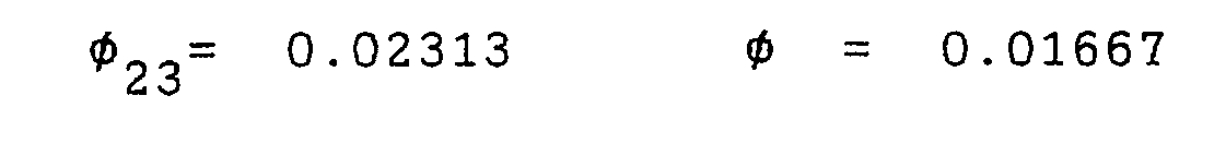
- Thus,

- It is obvious that the
objective lens system 60 satisfies the inequality (9). Further,


- It is also obvious that the
objective lens system 60 satisfies the inequalities (11 A) and (11 B). In addition,


- It is also obvious that the
objective lens system 60 satisfies the inequalities (12A) and (12B). - The
objective lens system 60 is an infinity corrected objective system and acts in combination with the imageformation lens system 150. Hence, the equation below gives the imaging magnification M of a microscope utilizing the imageformation lens system 150 and theobjective lens system 60.
- Figs. 15A and 15B illustrate spherical aberration and sine condition, respectively, in the optical system utilizing the
objective lens system 60 and the imageformation lens system 150, while Figs. 15C and 15D showing astigmatism and distortion at light of a wavelength of 298.06 nm, respectively. - According to Figs. 15A and 15B, serious aberrations at ultraviolet and far ultraviolet light do not occur in the
objective lens system 60. Thus, theobjective lens system 60 is obviously employable in ultraviolet and far ultraviolet range. In addition, astigmatism and distortion are restrained in the optical system in which theobjective lens system 60 is used (according to Figs. 15C and 15D). - The
objective lens systems - Though not having especially described in the specification, it is confirmed that aberrations at visible and infrared light are also effectively restrained according to the present invention. Thus, the
objective lens systems - Now referring again to the precedent applications, the objective lens system 160 (Fig. 2) is combined with the image
formation lens system 150, thereby to obtain the imaging magnification M of -10. More precisely, the focal length of theobjective lens system 160 is 30, whereas the focal length of any of theobjective lens systems objective lens system 160 with theobjective lens system 50 of the second embodiment while fixing the imageformation lens system 150 in the same position. - Each of the
objective lens systems objective lens system 160 as set forth. This eliminates time consuming process of bringing the microscope into focus after replacement (for example, after theobjective lens system 10 has replaced the objective lens system 160), whereby operation of the microscope would be greatly improved. - The
objective lens systems objective lens system 160. In consequence, the replacement accompanies only negligible changes in quantity of illumination light onto an object, promising fairy good observation. - An objective lens system according to a third embodiment of the present invention includes a first to a third lens groups disposed in that order from an object side to an image formation side with predetermined air spacings therebetween. The first lens group includes a lens which is made of either quartz or fluorite and which has a positive power. The second lens group includes a lens which is made of quartz and which has a negative power. The third lens group includes a lens pair or two lens pairs spaced apart from each other. Each lens pair consists of a negative lens made of quartz and a positive lens made of fluorite, the lenses being apart from each other. Thus, light in the ultraviolet or far ultraviolet region can transmit the objective lens system. In consequence, the objective lens system is useful in the ultraviolet and far ultraviolet regions.
- In addition to this, the respective lenses are separated from each other at predetermined air intervals. Therefore, the optical contact is not required and the objective lens system can be provided at low cost.
- Furthermore, the third lens group is provided with the lens pair which consists of the positive lens made of fluorite and the negative lens made of quartz. This allows various aberrations such as spherical aberration and chromatic aberration to correct.
- The objective lens system according to the third embodiment is interchangeable with other objective lens system, according to the precedent applications, for forming an image by cooperating with an image formation lens system. In the objective lens system, correction of chromatic aberration is carried out through the third lens group consisting of the positive lens and the negative lens. The second lens group having the large negative power is provided between the first and the third lens groups so that the objective lens system is a so-called telephoto type lens system. Thus, the focal length of the objective lens system grows larger compared to the total length thereof.
- The first lens group having the positive power is provided so that the objective lens system has a telecentric characteristic on the object side.
- From another viewpoint, a composite lens system consisting of the second and the third lens groups has a large focal length and functions as a teleconverter of the first lens group. That is, the composite lens system magnifies the focal length of the first lens group to adjust the focal length of the objective lens system to a desired value.
- For satisfying this condition accurately, the following equation must be satisfied:

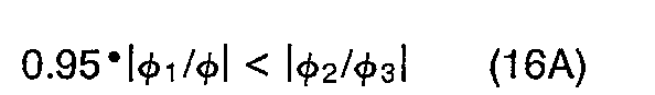

- In the case of forming the image of the object through only the lens pair, the value |φ+/φ-| is preferably set within the range of 1.3 to 1.4 in consideration of the dispersion of fluorite and quartz, where φ+, φ- are powers of the positive and the negative lenses of the third lens group, respectively. However, when the objective lens system includes the first to the third lens groups, it is rather preferable that the aberration caused by the first and the second lens groups is corrected through the third lens group. Hence, it is preferable to set the value |φ+/φ-| within the range of 1.00 to 1.20, that is, to set the objective lens system to satisfy the following inequality (17):

- Furthermore, in order to attain parfocality, the objective lens system must satisfy the following inequality (18):
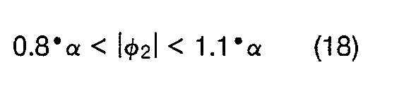

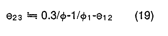
- For providing the objective lens system with the telecentric characteristic on the object side, the pupil of the composite lens system consisting of the second and the third lens groups is required to coincide with the focal point of the first lens group. Accordingly, the condition represented by the following expression can be obtained:

- When the conditions (19) and (20) are taken into consideration, the objective lens system is required to satisfy the inequality (18).
- Fig. 16 is a block diagram of an objective lens system according to a preferred example of the third embodiment. In Fig. 16, an
objective lens system 70 includes a first to a third lens groups LG1 to LG3. The first to the third lens groups LG1 to LG3 are arranged at predetermined air intervals serially from an object side (left-hand side of the figure) to an image side (right-hand side of the figure). The first lens group LG1 includes alens 71 having a positive power, and the second lens group LG2 includes a lens 72 having a negative power. The third lens group LG3 includes two lens pairs LP1 and LP2 arranged at a predetermined air interval. In the lens pair LP1, a lens 73 having a negative power and a lens 74 having a positive power are arranged at a predetermined air interval serially from the object side to the image side. Similarly, in the lens pair LP2, a negative lens 75 and a positive lens 76 are arranged at a predetermined air interval serially from the object side to the image side. - The following table 8 shows lens data of the objective lens system 70:
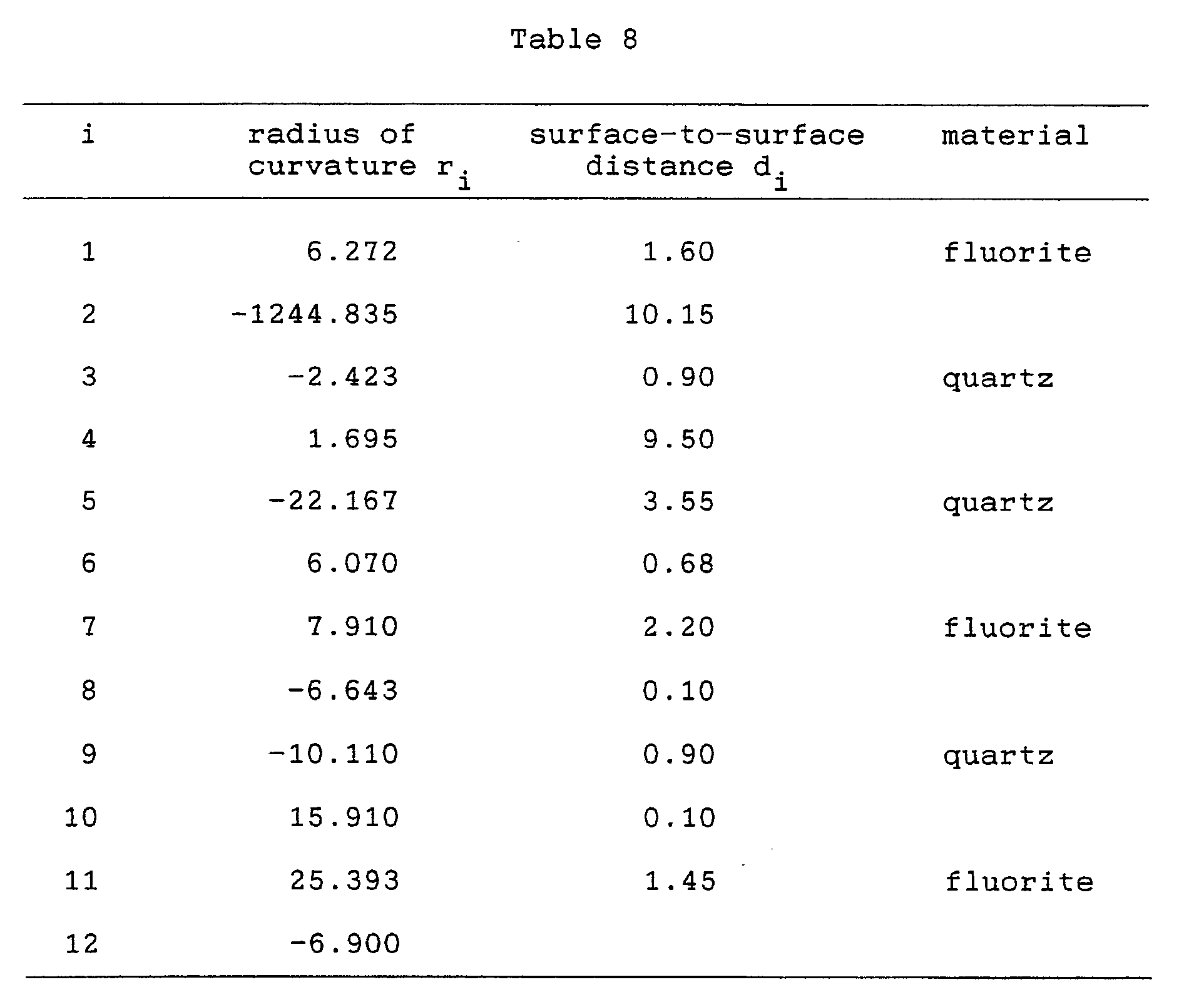
lenses 71, 74 and 76 are made of fluorite. - The focal length f of the
objective lens system 70 is 150, the numerical aperture (NA) thereof is 1/60, and the image size thereof is 10.6. - With respect to the wavelength of 298.06 (nm), powers φ1, φ2 and φ3 of the first to third lens groups LG1, LG2 and LG3, and a power φ of the entire system (the objective lens system 70) are respectively as follows:


- Powers φ-1, and φ+1 of the lenses 73 and 74 and powers 0-2 and φ+2 of the lenses 75 and 76 are as follows:


- An interval e12, between principal points of a lens system consisting of the first and the second lens groups LG1 and LG2 is as follows:
- e12 = 11.58
- Thus,


- It is obvious that the
objective lens system 70 satisfies the inequalities (16A) and (16B), respectively. Further,

- It is also obvious that the
objective lens system 70 satisfies the inequality (17). In addition,

- It is also obvious that the
objective lens system 70 satisfies the inequality (18). - The
objective lens system 70 is an infinity corrected objective system and acts in combination with the imageformation lens system 150. Hence, the equation below gives the imaging magnification M of a microscope utilizing the imageformation lens system 150 and theobjective lens system 70.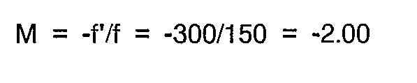
- Figs. 17A and 17B illustrate spherical aberration and sine condition, respectively, in the optical system utilizing the
objective lens system 70 and the imageformation lens system 150, while Figs. 17C and 17D showing astigmatism and distortion at light of a wavelength of 298.06 nm, respectively. - According to Figs. 17A and 17B, serious aberrations at ultraviolet and far ultraviolet light do not occur in the
objective lens system 70. Thus, theobjective lens system 70 is obviously employable in ultraviolet and far ultraviolet range. In addition, astigmatism and distortion are restrained in the optical system in which theobjective lens system 70 is used (according to Figs. 17C and 17D). - Fig. 18 is a block diagram of an objective lens system according to another example of the third embodiment. An
objective lens system 80 according to the second preferred embodiment is basically similar to theobjective lens system 70 in structure, except that the third lens group LG3 is composed of one lens pair LP1 in the eighth example. - The following table 9 shows lens data of the objective lens system 80:

lenses 82 and 83 are made of quartz, where thelenses 81 and 84 are made of fluorite. - The focal length f of the
objective lens system 80 is 150, the numerical aperture (NA) thereof is 1/60, and the image size thereof is 10.6. - With respect to the wavelength of 298.06 (nm), powers φ1, φ2 and φ3 of the first to the third lens groups LG1, LG2 and LG3, and a power φ of the entire system (the objective lens system 80) are respectively as follows:


- Powers φ- and φ+ of the
lenses 
- An interval el2 between principal points of a lens system consisting of the first and the second lens groups LG1 and LG2 is as follows:
- e12 = 10.32
- Thus,


- It is obvious that the
objective lens system 80 satisfies the inequalities (16A) and (16B), respectively. Further,
- It is also obvious that the
objective lens system 80 satisfies the inequality (17). In addition,

- It is also obvious that the
objective lens system 80 satisfies the inequality (18). - The
objective lens system 80 is an infinity corrected objective system and acts in combination with the imageformation lens system 150. Hence, the equation below gives the imaging magnification M of a microscope utilizing the imageformation lens system 150 and theobjective lens system 80.
- Figs. 19A and 19B illustrate spherical aberration and sine condition, respectively, in the optical system utilizing the
objective lens system 80 and the imageformation lens system 150, while Figs. 19C and 19D showing astigmatism and distortion at light of a wavelength of 298.06 nm, respectively. - According to Figs. 19A and 19B, serious aberrations at ultraviolet and far ultraviolet light do not occur in the
objective lens system 80. Thus, theobjective lens system 80 is obviously employable in ultraviolet and far ultraviolet range. In addition, astigmatism and distortion are restrained in the optical system in which theobjective lens system 80 is used (according to Figs. 19C and 19D). - Fig. 20 is a block diagram of an objective lens system according to another example of the third embodiment. An
objective lens system 90 is identical to theobjective lens system 80 in structure. - Table 10 shows lens data of the objective lens system 90:

- As will be understood from Table 10, the lenses 91 to 93 are made of quartz and the
lens 94 is made of fluorite. - The focal length f of the
objective lens system 90 is 150, the numerical aperture (NA) thereof is 1/60, and the image size thereof is 10.6. - With respect to the wavelength of 298.06 (nm), powers φ1, φ2 and φ3 of the first to the third lens groups LG1, LG2 and LG3, and a power φ of the entire system (the objective lens system 90) are respectively as follows:


- Powers φ- and φ+ of the
lenses 
- An interval e12 between principal points of a lens system consisting of the first and the second lens groups LG1 and LG2 is as follows:
- e12 = 11.35
- Thus,


- It is obvious that the
objective lens system 90 satisfies the inequalities (16A) and (16B), respectively. Further,
- It is also obvious that the
objective lens system 90 satisfies the inequality (17). In addition,

objective lens system 90 satisfies the inequality (18). - The
objective lens system 90 is an infinity corrected objective system and acts in combination with the imageformation lens system 150. Hence, the equation below gives the imaging magnification M of a microscope utilizing the imageformation lens system 150 and theobjective lens system 90.
- Figs. 21 A and 21 B illustrate spherical aberration and sine condition, respectively, in the optical system utilizing the
objective lens system 90 and the imageformation lens system 150, while Figs. 21 C and 21 D showing astigmatism and distortion at light of a wavelength of 298.06 nm, respectively. - According to Figs. 21 A and 21 B, serious aberrations at ultraviolet and far ultraviolet light do not occur in the
objective lens system 90. Thus, theobjective lens system 90 is obviously employable in ultraviolet and far ultraviolet range. In addition, astigmatism and distortion are restrained in the optical system in which theobjective lens system 90 is used (according to Figs. 21 C and 21 D). - The
objective lens systems - Though not having especially described in the specification, it is confirmed that aberrations at visible and infrared light are also effectively restrained according to the present invention. Thus, the
objective lens systems - Now referring again to the precedent applications, the objective lens system 160 (Fig. 2) is combined with the image
formation lens system 150, thereby to obtain the imaging magnification M of -10. More precisely, the focal length of theobjective lens system 160 is 30, whereas the focal length of any of theobjective lens systems objective lens system 160 with theobjective lens system 70 of the third embodiment while fixing the imageformation lens system 150 in the same position. - Each of the
objective lens systems objective lens system 160 as set forth. This eliminates time consuming process of bringing the microscope into focus after replacement (for example, after theobjective lens system 70 has replaced the objective lens system 160), whereby operation of the microscope would be greatly improved. - The
objective lens systems objective lens system 160. In consequence, the replacement accompanies only negligible changes in quantity of illumination light onto an object, promising fairy good observation. - Fig. 22 is a schematic block diagram of a
system 102 for measuring film thickness. Thesystem 102 includes amicrospectroscope 101 for detecting spectrum of a sample to be measured and anarithmetic unit 103 for calculating the film thickness of the measured sample S on the basis of spectral data obtained by themicrospectroscope 101. Themicrospectroscope 101 includes an illuminatingoptical system 110, a microscopicoptical system 120, a reflectingmirror 130, aspectroscopic unit 140, and a monitoringoptical system 145. - The illuminating
optical system 110 includes alight source 111 for projecting light which includes ultraviolet and far ultraviolet rays, acondenser lens 112, anaperture stop 113, afield stop 114 and anothercondenser lens 115. Thus, illuminating light from thelight source 111 is guided to the microscopicoptical system 120 through thecondenser lens 112, theaperture stop 113, thefield stop 114 and thecondenser lens 115. - The microscopic
optical system 120 includes anobjective lens system 121 which is identical to that shown in Fig. 3, an imageformation lens system 124 which is identical to that shown in Fig. 4 and abeam splitter 123 provided between theobjective lens system 121 and the imageformation lens system 124.Symbol 122 denotes a pupil position of theobjective lens system 121. - The illuminating light from the
light source 111 passes through thecondenser lens 112, theaperture stop 113, thefield stop 114 and thecondenser lens 115, and is guided to theobjective lens system 121 by thebeam splitter 123. The illuminating light is through theobjective lens system 121 and is applied onto the surface of a measured sample S. The sample S is supported by a sample holder (not shown). - Reflected light from the surface of the measured sample S is enlarged by the
lens 121 and imaged at a position close to the reflectingmirror 130, thebeam splitter 123 and the imageformation lens system 124. - The reflecting
mirror 130 is provided with apinhole 131. Reflected light Ls passing through thepinhole 131 enters thespectroscopic unit 140. - The
spectroscopic unit 140 is formed by adiffraction grating 141 for separating the reflected light Ls into spectral components and aphoto detector 142 for detecting the spectrum of the spectrally diffracted light. Thediffraction grating 141 may be prepared by a flat field type diffraction grating which images a spectrum on a flat plane. Alternatively, the diffraction grating may have a sweeper. Thephoto detector 142, which is formed by a photodiode array or a CCD, for example, is conjugate with thepinhole 131. Alternatively, thephoto detector 142 may include a photomultiplier. - Since the
spectroscopic unit 140 has the aforementioned structure, the reflected light Ls is separated into its spectral components by thediffraction grating 141, and the respective spectral components are received by thephoto detector 142, which in turn outputs a signal corresponding to the spectrum of the light Ls. - The light reflected by the reflecting
mirror 130 enters the monitoringoptical system 145, and is imaged at an image-formation position 147 through arelay lens 146. Thus, an enlarged image of the surface of the sample S is imaged on an image-formation plane, so that the measuring position of the sample S can be confirmed and focusing can be performed on the basis of the enlarged image. - Fig. 23 is a flow chart of a method of measuring film thickness. Prior to using the
measuring system 102, an operator inputs spectrum data B(X) of a sample (hereinafter referred to as "standard sample"), whose spectrum data is known, in thearithmetic unit 103 through a keyboard (not shown), to store the data in a memory (not shown) provided in thearithmetic unit 103. The standard sample may be prepared by a silicon substrate, a substrate which is deposited with aluminum on its surface, or the like. - Then the operator sets the standard sample on the sample holder of the microspectroscope 101 (step S1), and supplies a command for detecting calibration data to the
arithmetic unit 103. In response to a command from thearithmetic unit 103, themicrospectroscope 101 detects the spectrum of the standard sample, to store data B'(X) relating to the spectrum in the memory of the arithmetic unit 103 (step S2). - Then, the operator removes the standard sample from the
microspectroscope 101 and sets the measured sample S on the sample holder (step S3). Thereafter, the operator supplies a command to thearithmetic unit 103 to start measurement, so that themicrospectroscope 101 detects the spectrum of the measured sample S in response to a command from thearithmetic unit 103, to store data S'(X) relating to the spectrum thereof in the memory of the arithmetic unit 103 (step S4). - The data S'(X), B(X) and B'(X) stored in the memory are read (step S5) into the
arithmetic unit 103, to obtain data S(X) in accordance with the following expression:
- The data S(λ) corresponds to a signal from the
microspectroscope 101 on the assumption that absolutely no influence is caused by the factors such as spectral transmittance characteristics of the illuminatingoptical system 110 and the microscopicoptical system 120. In other words, the data S(X) shows the true spectrum of the measured sample S. - On the basis of the data S(X) obtained during step S5, the
arithmetic unit 103 calculates the thickness of the thin film (step S6). The principle of calculates film thickness is well known in the art, and hence description thereof is omitted. - As understood from the expression (21), the data S'(X) relating to the actually measured spectrum is calibrated in the aforementioned manner to obtain the data S(X) relating to the true spectrum, whereby the film thickness can be accurately measured.
- The present invention can be employed within the restricted to use within a system for measuring film thickness. The invention has general applications as an objective lens optical system.
- Although the present invention has been described and illustrated in detail, it is clearly understood that the same is by way of illustration and example only and is not to be taken by way of limitation. The spirit and scope of the present invention should be limited only by the terms of the appended claims.
- The features disclosed in the foregoing description, in the claims and/or in the accompanying drawings may, both separately and in any combination thereof, be material for realising the invention in diverse forms thereof.
Claims (12)


Applications Claiming Priority (6)
| Application Number | Priority Date | Filing Date | Title |
|---|---|---|---|
| JP74297/90 | 1990-03-23 | ||
| JP2074297A JP2582917B2 (en) | 1990-03-23 | 1990-03-23 | Microscope objective lens |
| JP2109849A JP2584526B2 (en) | 1990-04-24 | 1990-04-24 | Microscope objective lens |
| JP109849/90 | 1990-04-24 | ||
| JP112418/90 | 1990-04-27 | ||
| JP11241890A JPH049814A (en) | 1990-04-27 | 1990-04-27 | Objective lens for microscope |
Publications (3)
| Publication Number | Publication Date |
|---|---|
| EP0448094A2 true EP0448094A2 (en) | 1991-09-25 |
| EP0448094A3 EP0448094A3 (en) | 1992-09-02 |
| EP0448094B1 EP0448094B1 (en) | 1995-06-14 |
Family
ID=27301465
Family Applications (1)
| Application Number | Title | Priority Date | Filing Date |
|---|---|---|---|
| EP91104423A Expired - Lifetime EP0448094B1 (en) | 1990-03-23 | 1991-03-21 | Objective lens system for use within microscope |
Country Status (3)
| Country | Link |
|---|---|
| US (1) | US5159492A (en) |
| EP (1) | EP0448094B1 (en) |
| DE (1) | DE69110325T2 (en) |
Families Citing this family (8)
| Publication number | Priority date | Publication date | Assignee | Title |
|---|---|---|---|---|
| US5469299A (en) * | 1990-05-15 | 1995-11-21 | Olympus Optical Co., Ltd. | Objective lens system |
| JPH0519162A (en) * | 1991-05-02 | 1993-01-29 | Asahi Optical Co Ltd | Objective lens and method of measuring objective lens |
| DE4219205A1 (en) * | 1992-06-12 | 1993-12-16 | Leica Mikroskopie & Syst | Process for the production of UV microscope dry lenses and microscope lenses produced by this process |
| US5532873A (en) * | 1993-09-08 | 1996-07-02 | Dixon; Arthur E. | Scanning beam laser microscope with wide range of magnification |
| DE19931949A1 (en) * | 1999-07-09 | 2001-01-11 | Leica Microsystems | DUV-compatible microscope lens with parfocal IR focus |
| JP2001108523A (en) * | 1999-10-14 | 2001-04-20 | Matsushita Electric Ind Co Ltd | Spectrometer |
| TWI656376B (en) | 2017-08-30 | 2019-04-11 | 大立光電股份有限公司 | Image capturing system lens group, image capturing device and electronic device |
| CN119667902B (en) * | 2024-12-24 | 2025-10-21 | 东方晶源微电子科技(北京)股份有限公司 | Deep UV microscope objectives and microscopes |
Family Cites Families (5)
| Publication number | Priority date | Publication date | Assignee | Title |
|---|---|---|---|---|
| US2363770A (en) * | 1943-09-22 | 1944-11-28 | Spencer Lens Co | Lens system |
| US3035490A (en) * | 1958-12-31 | 1962-05-22 | Ibm | Ultra-violet lens |
| JPS5436747A (en) * | 1977-08-26 | 1979-03-17 | Olympus Optical Co Ltd | Objective lens of microscope |
| US4349249A (en) * | 1980-05-21 | 1982-09-14 | The United States Of America As Represented By The United States Department Of Energy | Compound lens |
| US5121255A (en) * | 1988-06-21 | 1992-06-09 | Dainippon Screen Mfg. Co. | Objective lens system for microscope |
-
1991
- 1991-03-20 US US07/672,864 patent/US5159492A/en not_active Expired - Fee Related
- 1991-03-21 EP EP91104423A patent/EP0448094B1/en not_active Expired - Lifetime
- 1991-03-21 DE DE69110325T patent/DE69110325T2/en not_active Expired - Fee Related
Also Published As
| Publication number | Publication date |
|---|---|
| EP0448094B1 (en) | 1995-06-14 |
| US5159492A (en) | 1992-10-27 |
| DE69110325T2 (en) | 1995-10-19 |
| DE69110325D1 (en) | 1995-07-20 |
| EP0448094A3 (en) | 1992-09-02 |
Similar Documents
| Publication | Publication Date | Title |
|---|---|---|
| US5311021A (en) | Spectroscopic sampling accessory having dual measuring and viewing systems | |
| US5121255A (en) | Objective lens system for microscope | |
| Maksutov | New catadioptric meniscus systems | |
| JPH10221607A (en) | Confocal microscope | |
| US5235465A (en) | Objective lens system for use within microscope | |
| US6038066A (en) | Arrangement for generating a defined longitudinal chromatic aberration in the optical beam path of a confocal microscope | |
| EP2610662B1 (en) | Microscope optical assembly and microscope system | |
| JPH03188407A (en) | Ultraviolet ray conforming dry objective lens of microscope | |
| EP0447990B1 (en) | Objective lens system for use within microscope | |
| EP0448094B1 (en) | Objective lens system for use within microscope | |
| Mohanan et al. | Understanding the limits of remote focusing | |
| US20040207841A1 (en) | Spectroscope confocal, opitcal system using the same, and scanning microscope | |
| US4934801A (en) | Optical imaging system | |
| US6018416A (en) | Secondary image formation type view finder | |
| EP0452963A2 (en) | Objective lens system for use within microscope | |
| US4768869A (en) | Catadioptric imaging system | |
| JP2018537708A (en) | Broadband catadioptric microscope objective with a small central shield | |
| US7706076B2 (en) | Optical system | |
| EP3798711A1 (en) | Imaging device and method for imaging an object using a microscope | |
| US20060285219A1 (en) | Tube lens unit with chromatically compensating effect | |
| SU1658114A1 (en) | Planapochromatic objective lens of microscope | |
| US4842384A (en) | Optical system of the Petzval type | |
| JP4792170B2 (en) | Objective lens assembly for microscope | |
| JP2003156691A (en) | Condenser lens for microscope | |
| JP2584526B2 (en) | Microscope objective lens |
Legal Events
| Date | Code | Title | Description |
|---|---|---|---|
| PUAI | Public reference made under article 153(3) epc to a published international application that has entered the european phase |
Free format text: ORIGINAL CODE: 0009012 |
|
| AK | Designated contracting states |
Kind code of ref document: A2 Designated state(s): DE FR GB |
|
| PUAL | Search report despatched |
Free format text: ORIGINAL CODE: 0009013 |
|
| AK | Designated contracting states |
Kind code of ref document: A3 Designated state(s): DE FR GB |
|
| 17P | Request for examination filed |
Effective date: 19921204 |
|
| 17Q | First examination report despatched |
Effective date: 19940707 |
|
| GRAA | (expected) grant |
Free format text: ORIGINAL CODE: 0009210 |
|
| AK | Designated contracting states |
Kind code of ref document: B1 Designated state(s): DE FR GB |
|
| PG25 | Lapsed in a contracting state [announced via postgrant information from national office to epo] |
Ref country code: FR Effective date: 19950614 |
|
| REF | Corresponds to: |
Ref document number: 69110325 Country of ref document: DE Date of ref document: 19950720 |
|
| EN | Fr: translation not filed | ||
| PLBE | No opposition filed within time limit |
Free format text: ORIGINAL CODE: 0009261 |
|
| 26N | No opposition filed | ||
| PGFP | Annual fee paid to national office [announced via postgrant information from national office to epo] |
Ref country code: GB Payment date: 20000315 Year of fee payment: 10 |
|
| PGFP | Annual fee paid to national office [announced via postgrant information from national office to epo] |
Ref country code: DE Payment date: 20000318 Year of fee payment: 10 |
|
| PG25 | Lapsed in a contracting state [announced via postgrant information from national office to epo] |
Ref country code: GB Free format text: LAPSE BECAUSE OF NON-PAYMENT OF DUE FEES Effective date: 20010321 |
|
| GBPC | Gb: european patent ceased through non-payment of renewal fee |
Effective date: 20010321 |
|
| PG25 | Lapsed in a contracting state [announced via postgrant information from national office to epo] |
Ref country code: DE Free format text: LAPSE BECAUSE OF NON-PAYMENT OF DUE FEES Effective date: 20020101 |