EP0448179A2 - Schwingende Vorrichtung zum Fördern und Trennen und Spannvorrichtung dazu - Google Patents
Schwingende Vorrichtung zum Fördern und Trennen und Spannvorrichtung dazu Download PDFInfo
- Publication number
- EP0448179A2 EP0448179A2 EP91200644A EP91200644A EP0448179A2 EP 0448179 A2 EP0448179 A2 EP 0448179A2 EP 91200644 A EP91200644 A EP 91200644A EP 91200644 A EP91200644 A EP 91200644A EP 0448179 A2 EP0448179 A2 EP 0448179A2
- Authority
- EP
- European Patent Office
- Prior art keywords
- screen
- clamp
- conveyor bed
- lever arm
- hook
- Prior art date
- Legal status (The legal status is an assumption and is not a legal conclusion. Google has not performed a legal analysis and makes no representation as to the accuracy of the status listed.)
- Granted
Links
Images



Classifications
-
- B—PERFORMING OPERATIONS; TRANSPORTING
- B07—SEPARATING SOLIDS FROM SOLIDS; SORTING
- B07B—SEPARATING SOLIDS FROM SOLIDS BY SIEVING, SCREENING, SIFTING OR BY USING GAS CURRENTS; SEPARATING BY OTHER DRY METHODS APPLICABLE TO BULK MATERIAL, e.g. LOOSE ARTICLES FIT TO BE HANDLED LIKE BULK MATERIAL
- B07B1/00—Sieving, screening, sifting, or sorting solid materials using networks, gratings, grids, or the like
- B07B1/46—Constructional details of screens in general; Cleaning or heating of screens
- B07B1/48—Stretching devices for screens
-
- B—PERFORMING OPERATIONS; TRANSPORTING
- B07—SEPARATING SOLIDS FROM SOLIDS; SORTING
- B07B—SEPARATING SOLIDS FROM SOLIDS BY SIEVING, SCREENING, SIFTING OR BY USING GAS CURRENTS; SEPARATING BY OTHER DRY METHODS APPLICABLE TO BULK MATERIAL, e.g. LOOSE ARTICLES FIT TO BE HANDLED LIKE BULK MATERIAL
- B07B1/00—Sieving, screening, sifting, or sorting solid materials using networks, gratings, grids, or the like
- B07B1/46—Constructional details of screens in general; Cleaning or heating of screens
Definitions
- This invention relates generally to vibratory conveying and separating apparatus having replaceable screens which are driven by a vibratory drive that vibrates the screens in a forward and upward direction.
- Vibratory conveyors and shakers are commonly used for dewatering, separating and grading various material, such as for example fruits and vegetables.
- Such conveyors comprise a working conveyor bed mounted to a frame, and a vibratory exciter arranged to impart vibrating motion to the conveyor bed.
- the conveyor bed is provided with a screen deck which is conventionally a rigid apertured bed made up of a plurality of screening panels.
- the screening panels are removably mounted to the conveyor bed frame such that different mesh panels can be substituted depending upon the material being processed, and for replacement of the screens upon excessive wear.
- a great challenge in the design and maintenance of such conveyors is to provide a bed which enables the screen panels to be rigidly held in place relative to the conveyor bed, and yet easily removed when one desires to change a screen.
- FIG. 3 is a vertical and partial section view of a conveyor bed 10 illustrating a screen panel 12 being clamped relative thereto by a prior art clamping device 14.
- the product being processed and conveyed by conveyor bed 10 would move into the page upon which Fig. 3 appears.
- Clamp 14 is vertically oriented, and the vibratory drive (not shown) would vibrate bed 10 and screens 12 upwardly and forwardly at an inclined angle generally into the direction of the page.
- Clamp 14 includes a hook member 16 which is pivotally mounted relative to a lever arm 18 and a mounting base 20 for imparting a vertically downward clamping force against screen 12.
- Screen 12 is clamped vertically downward against an inner side rail 36 of conveyor bed 10.
- mounting base 20 is welded or otherwise secured to the external surface of conveyor bed frame 10.
- Base 20 pivotally supports lever arm 18 relative thereto at one of the lever arm ends for pivoting about a horizontal axis 22.
- Hook member 16 is also pivotally mounted relative to lever arm 18 by a horizontal pivot rod 24.
- Hook 16 is threaded at its lower end and threadably receives a tension adjustable nut 28.
- a tension spring 26 is received between pivot rod 24 and nut 28.
- the upper hooking portion of hook member 16 is received through a side opening 30 which is formed in conveyor bed frame 10. Opening 30 is elongated in the vertical direction to accommodate the insertion and removal of hook 16 therethrough the result of the vertical arcing movement of the upper portion of hook 16 by pivot action about pivot axis 22. This would otherwise create a large opening in the side of conveyor bed 10 through which some of the material being processed would fall to the ground and be lost.
- a bent metal guard 32 is affixed to the internal surface of conveyor bed frame 10 and covers opening 30. Guard 32 is secured to frame 10 at its upper end and includes an upwardly angled portion 34 at its lower end against which hook 16 bears.
- This lower portion 34 is slidable relative to bed frame 10 such that a clamping force applied against lower portion 34 will be transmitted vertically downward onto screen 12.
- Guard 32 and the position of hook 16 provide a disadvantage of projecting into the processing path of the material being conveyed. This reduces the effective width of the processing bed.
- a camming-lock clamping action is provided by lever arm 18 and pivot rod 24 relative to mounting block 20.
- a locking clamp force is provided by camming action when pivot rod 24 is rotated to a location beneath an imaginary line 38 defined by the tip of clamp hook 16 and pivot axis 22.
- Such conveyor beds are not without disadvantages.
- the excessive vibratory force necessary to impart the conveying action has been found on occasion to cause mounting blocks 20 to separate relative to conveyor bed frame 10.
- the downward clamping force must be large as it must clamp the screen relative to the bed which is being vibrated with a force having another directional component.
- the orientation of hook 16 and guard 32 relative to conveyor bed 10 reduces the effective width of the processing conveyor, as previously described.
- Vibratory conveyor 100 includes a conveyor bed 102 and an overhead vibratory drive frame assembly 104. Vibratory drive frame assembly 104 is supported by vertical supports 105.
- Conveyor bed 102 and drive assembly 104 are interconnected by a series of leaf springs 106 which function as a support means for resiliently supporting conveyor bed 102 for vibration.
- Drive frame assembly 104 includes a drive means 108 for vibrating conveyor bed 102 through leaf springs 106 in a forward and upward direction at a predetermined forward and upward angle of inclination "A", alternately termed the upward vibration angle.
- This angle of inclination A is preferably approximately 22.5 degrees relative to horizontal, with leaf springs 106 being oriented substantially normal to the predetermined angle of inclination.
- Drive means 108 preferably applies a substantially linear vibratory drive force along the forward and upward inclination angle.
- alternative drives and conveyor bed assemblies could be usable without departing from the principles and scope of the invention, as will be apparent from the continuing discussion and concluding claims.
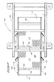
- Conveyor bed 102 is generally rectangular in shape having a rearward infeed end 110 and a forward discharge end 112. Supported internally within the frame of conveyor bed 102 are processing screens 114 which receive, convey and separate material being processed. Processing screens 114 have a general horizontal orientation, yet are positioned at a slight prescribed forwardly inclined screen angle "B" (Fig. 1). Such general horizontal orientation requires that drive assembly 104 convey the material being processed across the generally horizontal processing screens as well as provide a shaking function thereto to effect separation of small size material through the screens. As is apparent from the drawings, vibration angle "A" is different and greater than prescribed screen angle "B". Conventional prior art support rails 113 are provided for supporting processing screen 114 at a slight upward and forward angle of inclination relative to the general horizontal orientation of bed 114.
- At least one releasable clamp 116 engages between conveyor bed 102 and each processing screen 114 to provide a releasable clamping force against the screen to clamp it to the conveyor bed.
- the clamp is mounted to orient the releasable clamping force substantially parallel with the predetermined forward and upward angle of inclination A. This provides an advantage of reducing the wear on the clamping components by aligning the clamping force with the vibratory force. This minimizes any lateral movement and forces from being applied to the clamping device.
- only one clamp 116 engages each of the opposite sides of each processing screen 114 the result of the alignment of the clamping force and vibratory force.
- clamp device 116 is mounted to the side of conveyor bed 102.
- Clamp 116 is defined by a mounting base 118, a clamp hook 120 and a pivotally interconnecting elongated lever arm 122.
- Mounting base 118 is welded or otherwise secured to the side of conveyor bed 102, and is provided with a longitudinally elongated slot 124.
- Lever arm 122 has a rough outline shape similar in appearance to the numeral "4", as shown in Fig. 5. It has first and second ends 126, 128, respectively.
- lever arm 122 in edge view is in the shape of a "U".
- Lever arm 122 operably engages mounting base 118 by a first pivot rod nut and bolt assembly 130 which extends across first end 126, and into and through mounting base slot 124.
- a second pivot rod 132 is received by lever arm 122 intermediate first pivot rod 130 and second lever arm end 128.
- Second pivot rod 132 operably engages clamp hook 120 for pivotally supporting clamp hook 120 and lever arm 124 relative to one another.
- clamp hook 120 includes a hook portion 134 and a stem portion 136 extending therefrom.
- Second pivot rod 132 is defined by a large central section 138 and smaller outer opposing pins 140 and 142 which are pivotally received within aligned holes formed on the opposing sides of lever arm 122.
- a transverse hole is provided within large central section 138 in second pivot rod 132 through which stem portion 136 of clamp hook 120 slidably extends. In this manner, hook 120 is slidably received relative to second pivot rod 132.
- External threads 144 are formed on the lower end of stem portion 136. Threads 144 threadably receive an adjustable tension nut assembly 146. Nut assembly 146 is longitudinally moveable along stem 136 by rotation of the nut relative to the external stem threads 144 to adjust the clamping tension of clamp hook 120, as will be more fully described below. Nut assembly 146 in operation bears perpendicularly relative to central portion 138 of second pivot rod 132. Nut assembly 146 and threads 144 define an adjustable locking means for restricting movement of stem 136 relative to second pivot rod 132 when clamping hook 120 is in a clamping position. They also provide a means for adjusting the clamping force applied against screen 114 as will be apparent from the continuing discussion.
- Conveyor bed 102 is provided with a side clamp opening 148, with clamp mounting base 118 being mounted adjacent thereto such that clamp hook portion 134 is extendable through opening 148.
- Processing screens 114 are generally rectangular in shape being defined by a perforated sheet 150 supported by a screen frame 152. Each processing screen 114 includes a rearward and forward end 154, 156, respectively, and opposing outer first and second screen sides 158, 160, respectively. (Figs. 1, 2, 4, and 5) Clamp hook 120 engages relative to the side of screen frame 152 and at a location beneath perforated sheet 150.
- screen frame 152 includes a side frame opening 162 which is smaller in diameter than conveyor bed opening 148.
- Side frame opening 162 is positioned on screen frame 152 to generally align with side clamp opening 148 when screen 114 is supported by conveyor bed 102.
- Clamp hook 120 in operation extends through side clamp opening 148 and into side frame opening 152.
- Conveyor bed 102 is provided with screen abutments 164 which are positioned to engage one of the rearward or forward screen ends, and are aligned perpendicular to the predetermined forward and upward angle of inclination A (Figs. 1 and 2.).
- clamps 116 are mounted relative to conveyor bed 102 to force a screen frame 152 rearwardly against abutments 164 to provide a clamping force which is substantially parallel to the angle of inclination of the applied vibratory force A.
- a screen 114 would be positioned relative to conveyor bed 102 to appropriately align screen opening 162 with the clamp opening 148 in bed 102.
- Lever arm 122 would be pivoted and positioned as shown in Fig. 6 such that pivot rod 130 is at the back or lower portion of mounting base slot 124. This will enable hook portion 134 to be pivoted about second pivot rod 132 such that it will be easily inserted through the side of conveyor bed 102 and into screen opening 162.
- lever arm 122 is pulled or pushed downwardly toward the side of bed 102 until hook pivot rod 132 "cams over" imaginary line 38 (Fig. 8) and clamps down into a holding position.
- the clamp would be released by first grasping the handle and rotating it away from the side of conveyor bed 102 until it is positioned substantially perpendicularly relative to conveyor bed 102 as shown in Fig. 7 at which point tension will be completely released.
- Lever arm 122 and first pivot rod 130 are then slid rearwardly along slot 124 in mounting base 118. Hook portion 134 can then be pivoted and removed from screen 114. Greater tightening of nut assembly 146 results in greater tension of the applied clamping force.
- hook 120 can be clamped relative to conveyor bed opening 148 when the screen is removed if nut assembly 146 is threaded sufficiently far enough up stem 136 of hook 120 to provide a clamping force where there is no screen. As shown, hook portion 134 is clamped against internal side surfaces 166 of conveyor bed opening 148.
Landscapes
- Combined Means For Separation Of Solids (AREA)
- Jigging Conveyors (AREA)
- Advancing Webs (AREA)
- Processing Of Solid Wastes (AREA)
Applications Claiming Priority (2)
| Application Number | Priority Date | Filing Date | Title |
|---|---|---|---|
| US496819 | 1990-03-21 | ||
| US07/496,819 US5037536A (en) | 1990-03-21 | 1990-03-21 | Vibratory conveying and separating apparatus and related clamping device |
Publications (3)
| Publication Number | Publication Date |
|---|---|
| EP0448179A2 true EP0448179A2 (de) | 1991-09-25 |
| EP0448179A3 EP0448179A3 (en) | 1991-12-04 |
| EP0448179B1 EP0448179B1 (de) | 1996-01-17 |
Family
ID=23974277
Family Applications (1)
| Application Number | Title | Priority Date | Filing Date |
|---|---|---|---|
| EP91200644A Expired - Lifetime EP0448179B1 (de) | 1990-03-21 | 1991-03-21 | Schwingende Vorrichtung zum Fördern und Trennen und Spannvorrichtung dazu |
Country Status (5)
| Country | Link |
|---|---|
| US (1) | US5037536A (de) |
| EP (1) | EP0448179B1 (de) |
| AT (1) | ATE133095T1 (de) |
| CA (1) | CA2036474C (de) |
| DE (1) | DE69116401D1 (de) |
Cited By (3)
| Publication number | Priority date | Publication date | Assignee | Title |
|---|---|---|---|---|
| EP0554963A1 (de) * | 1992-02-07 | 1993-08-11 | Superior B.V. | Klemmvorrichtung für Siebplatten |
| WO2000025943A3 (en) * | 1998-10-30 | 2000-08-03 | Tuboscope I P Inc | Screen assemblies for a vibratory separator |
| US9931672B2 (en) | 2016-04-08 | 2018-04-03 | W.S. Tyler Canada Ltd. | Side tensioning system for retaining screen media in a vibrating-type screening machine |
Families Citing this family (30)
| Publication number | Priority date | Publication date | Assignee | Title |
|---|---|---|---|---|
| US5392925A (en) * | 1993-08-12 | 1995-02-28 | Environmental Procedures, Inc. | Shale shaker and screen |
| US6371302B1 (en) | 1993-04-30 | 2002-04-16 | Tuboscope I/P, Inc. | Vibratory separator screens |
| US5647102A (en) * | 1995-11-07 | 1997-07-15 | Guyan Machinery Co. | Quick release clamp |
| US6155428A (en) * | 1996-10-15 | 2000-12-05 | Rig Technology Limited | Vibratory screening machine |
| US5981892A (en) * | 1996-12-06 | 1999-11-09 | Fmc Corporation | Food handling conveyor apparatus having sound detection means |
| DE19737093A1 (de) * | 1997-08-26 | 1998-07-09 | Herberts Pulverlack Gmbh | Hochleistungs-Unwucht-Siebmaschine |
| US6179128B1 (en) | 1998-10-02 | 2001-01-30 | Tuboscope I/P, Inc. | Tension clamp and screen system |
| US6070736A (en) * | 1998-11-09 | 2000-06-06 | Rotex, Inc. | Sealing mechanism and method for screening machines |
| US6250471B1 (en) | 1999-02-24 | 2001-06-26 | Key Technology, Inc. | Sorting apparatuses and sorting methods |
| US6283303B1 (en) | 1999-03-29 | 2001-09-04 | M-I L.L.C. | Vibrating screen separator, separating method, and clamping device |
| US6655523B2 (en) * | 2001-03-15 | 2003-12-02 | Key Technology, Inc. | Excited frame conveyor and excitation process for same |
| US6382424B1 (en) * | 2001-04-03 | 2002-05-07 | Christopher J. Bolton | Portable screening device and method |
| US6763948B2 (en) * | 2001-07-20 | 2004-07-20 | Rotex, Inc. | Screening machine with acceleration modification |
| US7497324B2 (en) * | 2005-01-20 | 2009-03-03 | Conveyor Dynamics Corporation | Conveyor system for two or more troughs |
| US20080223761A1 (en) * | 2007-03-14 | 2008-09-18 | Rotex, Inc. | Sealing Mechanism and Associated Sealing Method for Screening Machines |
| DE102007034512B3 (de) * | 2007-07-24 | 2008-06-26 | ThyssenKrupp Fördertechnik GmbH | Unwuchtantrieb für Siebmaschinen |
| US7918346B2 (en) * | 2008-05-31 | 2011-04-05 | Mark Roppo | Vibrating screen tensioning apparatus and method |
| ES2337438B1 (es) * | 2009-12-03 | 2011-02-18 | Jose Borrell S.A. | Maquina calibradora. |
| US8757392B2 (en) | 2011-11-23 | 2014-06-24 | Action Vibratory Equipment, Inc. | Flexible mat screening apparatus with offset supports |
| WO2014193428A1 (en) * | 2013-05-31 | 2014-12-04 | Key Technology, Inc. | Vibratory conveyor |
| US8978894B1 (en) * | 2013-09-09 | 2015-03-17 | Key Technology, Inc. | Clamp |
| JOP20190082A1 (ar) | 2016-10-14 | 2019-04-14 | Dirrick Corp | أجهزة وطرق وأنظمة للفرز الإهتزازي |
| US11052427B2 (en) | 2016-10-14 | 2021-07-06 | Derrick Corporation | Apparatuses, methods, and systems for vibratory screening |
| USD890236S1 (en) | 2019-02-07 | 2020-07-14 | Derrick Corporation | Vibratory screening machine |
| US11806755B2 (en) * | 2016-10-14 | 2023-11-07 | Derrick Corporation | Apparatuses, methods, and systems for vibratory screening |
| US11185801B2 (en) * | 2016-10-14 | 2021-11-30 | Derrick Corporation | Apparatuses, methods, and systems for vibratory screening |
| US11089810B2 (en) | 2018-04-26 | 2021-08-17 | Vibratory Solutions, Llc | Vibratory batter application |
| USD909166S1 (en) | 2019-06-05 | 2021-02-02 | Luis Alfonso Alva | Hook and clamp device |
| US11142409B1 (en) | 2020-04-27 | 2021-10-12 | Vibratory Solutions, Llc | Conveyor system with orientation of conveyed food products |
| CN118179929A (zh) * | 2024-04-24 | 2024-06-14 | 中南大学 | 一种分离装置及使用方法 |
Family Cites Families (17)
| Publication number | Priority date | Publication date | Assignee | Title |
|---|---|---|---|---|
| US1397343A (en) * | 1921-11-15 | Setts | ||
| US1242982A (en) * | 1916-10-16 | 1917-10-16 | Tyler Co W S | Screening device. |
| US1933561A (en) * | 1930-12-12 | 1933-11-07 | Lunsford Wesley | Grain separator |
| US2118782A (en) * | 1934-07-18 | 1938-05-24 | Nordberg Manufacturing Co | Screen |
| US2268853A (en) * | 1939-12-01 | 1942-01-06 | Simplicity Eng Co | Screen stretching and take-up device |
| US2284883A (en) * | 1940-02-17 | 1942-06-02 | Nordberg Manufacturing Co | Securing means for screen cloth |
| US2345364A (en) * | 1942-04-09 | 1944-03-28 | Sherbrooke Machineries Ltd | Diaphrage screen |
| US2378499A (en) * | 1943-03-15 | 1945-06-19 | Nordberg Manufacturing Co | Means of attachment for screen leaf springs |
| US2725984A (en) * | 1949-06-17 | 1955-12-06 | Ludwig Binder & Co | Vibratory conveyors |
| US2974798A (en) * | 1954-11-09 | 1961-03-14 | Ruzicka Jaroslav | Vibrating system |
| US3092573A (en) * | 1961-06-26 | 1963-06-04 | Jordan W Lambert | Vibrating screen clamp mechanism |
| GB1075906A (en) * | 1966-03-02 | 1967-07-19 | Fortschritt Veb K | Sieve arrangements |
| DK667974A (de) * | 1974-01-26 | 1975-09-15 | Powerscreen Int Ltd | |
| US4137157A (en) * | 1976-10-12 | 1979-01-30 | Deister Machine Company, Inc. | Screen tension assembly for vibratory screening apparatus |
| AU545288B2 (en) * | 1980-10-13 | 1985-07-11 | Dabmar Manufacturing Co. Pty. Ltd. | Vibrating screen |
| JPS6133679U (ja) * | 1984-07-31 | 1986-02-28 | 株式会社 安藤スクリ−ン製作所 | 振動篩機における篩網の緊張装置 |
| DE8617405U1 (de) * | 1986-06-30 | 1987-01-15 | Fa. Adolf u. Albrecht Eirich, 6969 Hardheim | Siebwerk |
-
1990
- 1990-03-21 US US07/496,819 patent/US5037536A/en not_active Expired - Lifetime
-
1991
- 1991-02-15 CA CA002036474A patent/CA2036474C/en not_active Expired - Fee Related
- 1991-03-21 DE DE69116401T patent/DE69116401D1/de not_active Expired - Lifetime
- 1991-03-21 AT AT91200644T patent/ATE133095T1/de not_active IP Right Cessation
- 1991-03-21 EP EP91200644A patent/EP0448179B1/de not_active Expired - Lifetime
Cited By (4)
| Publication number | Priority date | Publication date | Assignee | Title |
|---|---|---|---|---|
| EP0554963A1 (de) * | 1992-02-07 | 1993-08-11 | Superior B.V. | Klemmvorrichtung für Siebplatten |
| WO2000025943A3 (en) * | 1998-10-30 | 2000-08-03 | Tuboscope I P Inc | Screen assemblies for a vibratory separator |
| US9931672B2 (en) | 2016-04-08 | 2018-04-03 | W.S. Tyler Canada Ltd. | Side tensioning system for retaining screen media in a vibrating-type screening machine |
| US10421102B2 (en) | 2016-04-08 | 2019-09-24 | W.S. Tyler Canada Ltd. | Side tensioning system for retaining screen media in a vibrating-type screening machine |
Also Published As
| Publication number | Publication date |
|---|---|
| US5037536A (en) | 1991-08-06 |
| EP0448179A3 (en) | 1991-12-04 |
| DE69116401D1 (de) | 1996-02-29 |
| CA2036474A1 (en) | 1991-09-22 |
| ATE133095T1 (de) | 1996-02-15 |
| EP0448179B1 (de) | 1996-01-17 |
| CA2036474C (en) | 2001-02-06 |
Similar Documents
| Publication | Publication Date | Title |
|---|---|---|
| US5037536A (en) | Vibratory conveying and separating apparatus and related clamping device | |
| AU2019200761B2 (en) | Dual screen assembly for vibrating screening machine | |
| US5341939A (en) | Multiple deck vibrating screen apparatus | |
| TWI440511B (zh) | 預篩濾的方法與裝置 | |
| JPH07171501A (ja) | 調節可能なバースクリーン | |
| NO330613B1 (no) | Siktesystem, vibrasjonssikteapparat og fremgangsmate for montering av sikting | |
| US4732670A (en) | Tensioning assembly for vibratory screens | |
| DE2136279A1 (de) | Vibratorhalterung | |
| DE3440403C2 (de) | ||
| AU2014315613B2 (en) | Clamp | |
| US4906352A (en) | Improved tensioning assembly for vibratory screens | |
| JPH07505572A (ja) | スクリーンの取付け構造および張り構造 | |
| FR2631255A1 (fr) | Cadres amovibles de cribles type cassette ou cartouche | |
| EP0536847A1 (de) | Dichtungsschürze für die Laderinne eines Bandförderers | |
| US5755548A (en) | Belt drive tube feeder for a surface mount placement system | |
| JP2000189895A (ja) | 選別機 | |
| EP0422521B1 (de) | Filterpresse | |
| US6220447B1 (en) | Variable frequency screening apparatus | |
| CN212635931U (zh) | 一种用于生产阳角线传送装置的防震装置 | |
| RU2203151C2 (ru) | Устройство для очистки сыпучего материала от тяжелых включений | |
| KR0139486Y1 (ko) | 육절기의 냉동육 압지장치 | |
| KR20210076410A (ko) | 골절기의 띠톱 가이드 분리장치 | |
| WO1990004466A1 (en) | Screening device for particulate material | |
| DE2533561A1 (de) | Siebmaschine | |
| CN113663904A (zh) | 一种罐头食品加工中的畸形果实去除装置 |
Legal Events
| Date | Code | Title | Description |
|---|---|---|---|
| PUAI | Public reference made under article 153(3) epc to a published international application that has entered the european phase |
Free format text: ORIGINAL CODE: 0009012 |
|
| AK | Designated contracting states |
Kind code of ref document: A2 Designated state(s): AT BE CH DE DK ES FR GB GR IT LI LU NL SE |
|
| PUAL | Search report despatched |
Free format text: ORIGINAL CODE: 0009013 |
|
| AK | Designated contracting states |
Kind code of ref document: A3 Designated state(s): AT BE CH DE DK ES FR GB GR IT LI LU NL SE |
|
| 17P | Request for examination filed |
Effective date: 19920415 |
|
| 17Q | First examination report despatched |
Effective date: 19930726 |
|
| GRAA | (expected) grant |
Free format text: ORIGINAL CODE: 0009210 |
|
| AK | Designated contracting states |
Kind code of ref document: B1 Designated state(s): AT BE CH DE DK ES FR GB GR IT LI LU NL SE |
|
| PG25 | Lapsed in a contracting state [announced via postgrant information from national office to epo] |
Ref country code: CH Free format text: LAPSE BECAUSE OF FAILURE TO SUBMIT A TRANSLATION OF THE DESCRIPTION OR TO PAY THE FEE WITHIN THE PRESCRIBED TIME-LIMIT Effective date: 19960117 Ref country code: IT Free format text: LAPSE BECAUSE OF FAILURE TO SUBMIT A TRANSLATION OF THE DESCRIPTION OR TO PAY THE FEE WITHIN THE PRESCRIBED TIME-LIMIT;WARNING: LAPSES OF ITALIAN PATENTS WITH EFFECTIVE DATE BEFORE 2007 MAY HAVE OCCURRED AT ANY TIME BEFORE 2007. THE CORRECT EFFECTIVE DATE MAY BE DIFFERENT FROM THE ONE RECORDED. Effective date: 19960117 Ref country code: AT Effective date: 19960117 Ref country code: BE Effective date: 19960117 Ref country code: GR Free format text: LAPSE BECAUSE OF FAILURE TO SUBMIT A TRANSLATION OF THE DESCRIPTION OR TO PAY THE FEE WITHIN THE PRESCRIBED TIME-LIMIT Effective date: 19960117 Ref country code: FR Effective date: 19960117 Ref country code: ES Free format text: THE PATENT HAS BEEN ANNULLED BY A DECISION OF A NATIONAL AUTHORITY Effective date: 19960117 Ref country code: DK Effective date: 19960117 Ref country code: LI Free format text: LAPSE BECAUSE OF FAILURE TO SUBMIT A TRANSLATION OF THE DESCRIPTION OR TO PAY THE FEE WITHIN THE PRESCRIBED TIME-LIMIT Effective date: 19960117 |
|
| REF | Corresponds to: |
Ref document number: 133095 Country of ref document: AT Date of ref document: 19960215 Kind code of ref document: T |
|
| REF | Corresponds to: |
Ref document number: 69116401 Country of ref document: DE Date of ref document: 19960229 |
|
| PG25 | Lapsed in a contracting state [announced via postgrant information from national office to epo] |
Ref country code: LU Free format text: LAPSE BECAUSE OF NON-PAYMENT OF DUE FEES Effective date: 19960331 |
|
| PG25 | Lapsed in a contracting state [announced via postgrant information from national office to epo] |
Ref country code: SE Effective date: 19960417 |
|
| PG25 | Lapsed in a contracting state [announced via postgrant information from national office to epo] |
Ref country code: DE Effective date: 19960418 |
|
| EN | Fr: translation not filed | ||
| REG | Reference to a national code |
Ref country code: CH Ref legal event code: PL |
|
| PLBE | No opposition filed within time limit |
Free format text: ORIGINAL CODE: 0009261 |
|
| STAA | Information on the status of an ep patent application or granted ep patent |
Free format text: STATUS: NO OPPOSITION FILED WITHIN TIME LIMIT |
|
| 26N | No opposition filed | ||
| REG | Reference to a national code |
Ref country code: GB Ref legal event code: IF02 |
|
| PGFP | Annual fee paid to national office [announced via postgrant information from national office to epo] |
Ref country code: GB Payment date: 20100325 Year of fee payment: 20 |
|
| PGFP | Annual fee paid to national office [announced via postgrant information from national office to epo] |
Ref country code: NL Payment date: 20100325 Year of fee payment: 20 |
|
| REG | Reference to a national code |
Ref country code: NL Ref legal event code: V4 Effective date: 20110321 |
|
| REG | Reference to a national code |
Ref country code: GB Ref legal event code: PE20 Expiry date: 20110320 |
|
| PG25 | Lapsed in a contracting state [announced via postgrant information from national office to epo] |
Ref country code: NL Free format text: LAPSE BECAUSE OF EXPIRATION OF PROTECTION Effective date: 20110321 |
|
| PG25 | Lapsed in a contracting state [announced via postgrant information from national office to epo] |
Ref country code: GB Free format text: LAPSE BECAUSE OF EXPIRATION OF PROTECTION Effective date: 20110320 |