EP0448215B1 - Verfahren und Vorrichtung zur Überwachung eines Färbprozesses - Google Patents
Verfahren und Vorrichtung zur Überwachung eines Färbprozesses Download PDFInfo
- Publication number
- EP0448215B1 EP0448215B1 EP91301117A EP91301117A EP0448215B1 EP 0448215 B1 EP0448215 B1 EP 0448215B1 EP 91301117 A EP91301117 A EP 91301117A EP 91301117 A EP91301117 A EP 91301117A EP 0448215 B1 EP0448215 B1 EP 0448215B1
- Authority
- EP
- European Patent Office
- Prior art keywords
- color
- pattern
- firing time
- dye
- data
- Prior art date
- Legal status (The legal status is an assumption and is not a legal conclusion. Google has not performed a legal analysis and makes no representation as to the accuracy of the status listed.)
- Expired - Lifetime
Links
- 239000003086 colorant Substances 0.000 title claims abstract description 31
- 238000010304 firing Methods 0.000 claims abstract description 97
- 238000011068 loading method Methods 0.000 claims abstract description 25
- 238000000034 method Methods 0.000 claims abstract description 14
- 238000004043 dyeing Methods 0.000 claims abstract description 13
- 239000004753 textile Substances 0.000 claims abstract description 11
- 239000000758 substrate Substances 0.000 claims description 41
- 239000007788 liquid Substances 0.000 claims description 4
- 238000004891 communication Methods 0.000 claims 1
- 239000012530 fluid Substances 0.000 claims 1
- 239000000975 dye Substances 0.000 description 44
- 238000009981 jet dyeing Methods 0.000 description 13
- 230000004044 response Effects 0.000 description 8
- 238000000059 patterning Methods 0.000 description 5
- 230000008859 change Effects 0.000 description 4
- 230000007257 malfunction Effects 0.000 description 4
- 230000015654 memory Effects 0.000 description 4
- 230000008901 benefit Effects 0.000 description 2
- 230000008878 coupling Effects 0.000 description 2
- 238000010168 coupling process Methods 0.000 description 2
- 238000005859 coupling reaction Methods 0.000 description 2
- 230000001934 delay Effects 0.000 description 2
- 230000003287 optical effect Effects 0.000 description 2
- 230000008569 process Effects 0.000 description 2
- 238000003491 array Methods 0.000 description 1
- 239000001045 blue dye Substances 0.000 description 1
- 239000003795 chemical substances by application Substances 0.000 description 1
- 238000004140 cleaning Methods 0.000 description 1
- 238000010586 diagram Methods 0.000 description 1
- 238000001035 drying Methods 0.000 description 1
- 239000004744 fabric Substances 0.000 description 1
- 230000006870 function Effects 0.000 description 1
- 238000003384 imaging method Methods 0.000 description 1
- 239000000463 material Substances 0.000 description 1
- 238000002156 mixing Methods 0.000 description 1
- DJDSLBVSSOQSLW-UHFFFAOYSA-N mono(2-ethylhexyl) phthalate Chemical compound CCCCC(CC)COC(=O)C1=CC=CC=C1C(O)=O DJDSLBVSSOQSLW-UHFFFAOYSA-N 0.000 description 1
- 239000001044 red dye Substances 0.000 description 1
- 210000003813 thumb Anatomy 0.000 description 1
- 230000001131 transforming effect Effects 0.000 description 1
Images

Classifications
-
- D—TEXTILES; PAPER
- D06—TREATMENT OF TEXTILES OR THE LIKE; LAUNDERING; FLEXIBLE MATERIALS NOT OTHERWISE PROVIDED FOR
- D06B—TREATING TEXTILE MATERIALS USING LIQUIDS, GASES OR VAPOURS
- D06B11/00—Treatment of selected parts of textile materials, e.g. partial dyeing
- D06B11/0056—Treatment of selected parts of textile materials, e.g. partial dyeing of fabrics
- D06B11/0059—Treatment of selected parts of textile materials, e.g. partial dyeing of fabrics by spraying
Definitions
- This invention relates to the automatic generation of look-up tables used in a textile dyeing apparatus and, more particularly, to the generation of look-up tables in response to a requested pattern, color combination and given apparatus configuration.
- textile dyeing systems include several arrays or "color bars" comprised of individually controllable and addressable dye jets that are arranged in spaced, parallel relation generally above and across the path of a moving web of substrate. For a given desired pattern, each color bar is associated with a single color of dye.
- Positioned along the path of each dye stream is an individual, transversely directed stream of air capable of intersecting and diverting the respective individual dye stream into a catch basin.
- Each such diverting air stream is associated with a valve which is capable of interrupting the flow of air in accordance with internally supplied pattern data. Accordingly, each of the diverting streams of air may be interrupted in accordance with such pattern data and thereby initiate the flow of dye onto the substrate from the various respective dye jet locations along the length of the color bar.
- each color bar may have hundreds or thousands of individually controllable dye jets in order to generate a pattern having the desired complexity and lateral pattern resolution.
- Such electronic processing systems can be of a multiprocessor system including a host computer and a real-time computer.
- the real-time computer receives the raw source pattern data and forwards the data to the control system associated with the dyeing apparatus.
- the control system accepts the raw source pattern data in the form of a series of pixel codes.
- the pixel codes define those distinct areas of the pattern which may be assigned a distinguishing color.
- Each code specifies, for each pattern line, the dye jet response for a given dye jet position on each and every array. In a system having eight color bars, each pixel code therefore controls the response of eight separate dye jets (one per color bar) with respect to a single pattern line.
- pattern line is intended to describe a continuous line of single pattern elements extending across the substrate parallel to the patterning color bars.
- pattern lines have a thickness, measured in the direction of substrate travel, equal to the maximum permitted amount of substrate travel under the patterning color bars between color bar pattern data updates.
- pattern element as used herein, is intended to be analogous to the term “pixel” as that term is used in the field of electronic imaging.
- An operator's interface such as a workstation terminal, may be coupled to the host computer in the multiprocessor system.
- the workstation serves as the operator's interface for providing the input parameters to the host computer for each job of patterns to be generated on the substrate of the textile dyeing apparatus.
- the operator enters the input parameters as a "RUN LIST" which designates the type of substrate to be dyed and the types of patterns to be printed for each job.
- the RUN LIST input for the type of base to be dyed, accesses a base file which includes the firing time for each of the color bars in the dyeing apparatus.
- the RUN LIST entry for the type of pattern, accesses a stock keeping unit (SKU) file.
- SKU stock keeping unit
- the SKU file designates for each pixel code used in the pattern, the respective color bar associated therewith. With this information, the multiprocessor and control systems generate the individual firing instructions for each jet in each color bar.
- a known apparatus demultiplexes and distributes the sequence of pixel codes to a plurality of color bars, each color bar being comprised of multiple dye jets.
- the apparatus makes use of manually operable thumb wheel settings, associated with each color bar, to determine the time period during which each of the dye jets in the color bar is allowed to fire in response to a firing instruction, i.e., the "firing time".
- a firing instruction i.e., the "firing time”.
- the operator inputs in the RUN LIST the color bars associated with each pixel code.
- the system then generates a converted pattern of firing time instructions from the raw source pattern data.
- a sequence of pixel codes for a single pattern line may be "AABAB", where pixel code A produces a red color and pixel code B produces a blue color.
- the operator inputs the "color loading" of the machine into the system, i.e., which color bars contain which colors. For example, if color bar 1 contains the red dye and color bar 2 contains the blue dye, then the operator associates pixel code A with color bar 1 and pixel code B with color bar 2 in the RUN LIST. From this information, the pixel codes for each pattern line are converted into on/off firing instructions for each color bar.
- the sequence of pixel codes "AABAB” would generate the following firing instructions for the jets in color bar 1: On, On, Off, On, Off.
- the same sequence of pixel codes are converted to the following firing instructions: Off, Off, On, Off, On.
- the firing instructions are then stored in memory for the respective pattern. Once the pattern is ready to be run on the machine, the converted firing instructions are sent to the color bars, in accordance with the substrate travel beneath the color bars, for dyeing the substrate.
- the period of time during which any of the dye streams associated with a dye jet in a given color bar may be allowed to strike the substrate must be the same for all dye streams in the color bar, i.e., this control system is incapable of allowing one dye stream to dispense dye onto the substrate for a different period of time than another dye stream in the same color bar.
- this control system is incapable of allowing one dye stream to dispense dye onto the substrate for a different period of time than another dye stream in the same color bar.
- the only means for varying the color bar firing time is to manually change the thumbwheel settings. This presents a problem when the operator is running a sequence of jobs in the RUN LIST because it is not possible to change the firing time thumbwheel settings for a respective color bar quickly or precisely enough to avoid wasting the substrate material traveling beneath the color bars.
- a further problem with the above system is that the converted firing instructions require a tremendous amount of storage space. Thus, only a limited number of patterns can practicably be stored in the system.
- Another known system converts the raw source pattern data to firing instructions by electronically associating the source pattern data with pre-generated firing instruction data from a look-up table.
- the operator's RUN LIST includes the SKU number and the base number.
- the SKU file designates the appropriate color bar for each pixel code. The operator thus loads the color bar with the appropriate colored dye as determined by the SKU file.
- a separate look-up table is maintained for each color bar in the dyeing apparatus.
- a sequence of pixel codes "AABBAA” are each individually associated with a particular address in the look-up table.
- the patterns SKU file would designate pixel code A equaling color bar 1 and pixel code B equaling color bar 2.
- the operator then must load color bar 1 with the appropriate color for pixel code A and color bar 2 with the color for pixel code B.
- the following look-up tables are used wherein "FT" designates a firing time: LUT's BAR 1 BAR 2 A FT 0 B 0 FT
- Each pixel code in the sequence has an associated firing time instruction in the look-up table for each color bar. These instructions are fed to memories associated with each color bar.
- the memory associated with color bar 1 receives the following sequence of firing instructions: FT, FT, Off, Off, FT, FT.
- the memory associated with color bar 2 receives the following set of firing instructions: Off, Off, FT, FT, Off, Off.
- the look-up table translates the raw source pattern data into firing time data in accordance with the machine set up. Each time a new pattern, identified by a new SKU number and associated file, is to be run on the machine, a new look-up table must be generated for the pattern. This presents a problem due to the dye color loading in the color bars of the apparatus.
- the present invention overcomes these problems by the automatic, computer generation of look-up tables in response to the requested pattern, color combination and machine configuration.
- the system produces the look-up tables from the operator's RUN LIST in a four phase operation.
- the type of RUN LIST entry is determined and an appropriate table generated to store its information. If an entry is a Base entry, then a firing time table is generated for the particular substrate associated with the Base entry. If the entry is determined to be a Color entry, the second phase of operation generates a machine color table for the color loading configuration. If the entry is an SKU entry, then the third phase generates a pattern color table including the information from the respective SKU file identified by the SKU entry. The pattern color table associates each pixel code with a particular color name rather than a fixed color bar in the jet dying apparatus as previously was done. Thus, for example, the pixel code A is associated with a color name such as "red" rather than a particular color bar.
- the fourth phase of operation generates the look-up tables from the data provided in the firing time table, machine color table and pattern color table.
- the operator only needs to input the color entries for the machine color loading configuration to correctly generate the proper look-up tables for the requested pattern and substrate.
- the present invention further allows the operator to randomly load the colors into the machine's color bars irrespective of the patterns to be run.
- the system software automatically generates the correct look-up tables for the particular machine configuration.
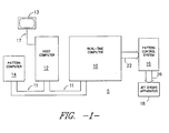
- Figure 1 is a block diagram illustrating a multiprocessor and pattern control system environment in which the present invention may operate.
- Figure 2 is a diagrammatic side elevation view of a jet dyeing apparatus to which the present invention is particularly well adapted.
- Figure 3 is a schematic side elevation view of the apparatus of Figure 2, showing only a single dye jet color bar and its operative connection to a liquid dye supply system as well as several electronic subsystems associated with the apparatus.
- Figure 4 is a flow chart describing the operation of the present invention.
- Figure 5 is a flow chart describing the operation of the present invention.
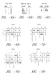
- Figures 6A-6D illustrate a firing time table, machine color table, pattern color table and look-up tables, respectively, for an example of the present invention.
- FIGS 7A-7F illustrate further examples of the present invention.
- the multiprocessor patterning system 5 is shown having a host computer 12 coupled via a bus 11 to a real-time computer 10.
- Optional pattern computer 14 is further coupled to the host computer 12 and real-time computer 10 by the bus 11. It is readily apparent that the coupling of the pattern computer 14, host computer 12 and real-time computer 10 may be by any means for coupling a local area network (LAN) such as an Ethernet bus.
- LAN local area network
- a pattern control system 16 is coupled via bus 26 to a jet dyeing apparatus 18.
- the jet dyeing apparatus 18 is described in greater detail in Figures 2 and 3.
- the pattern control system 16 receives input data over bus 22 from the real-time computer 10.
- Optional pattern computer 14 may be provided to allow a user of the system to quickly create their own pattern design.
- pattern designs may be pre-loaded onto magnetic or optical media for reading into the system.
- Each design has an associated stock keeping unit (SKU) file for providing the set-up parameters for the system for each pattern.
- SKU stock keeping unit
- An SKU file includes the pattern name for the pattern to be printed, the associated color names for each pixel code in the pattern, and a base reference ID identifying the substrate on which the pattern is to be printed.
- the base reference ID accesses a base file containing the firing times for each color bar in the jet dyeing apparatus 18 for that particular substrate.
- a simplified example of an SKU file for several patterns and a Base file are given below in Tables A and B.
- Tables A and B are given below in Tables A and B.
- only two pixel codes, A and B are used in the designated pattern. It is readily apparent however, that any number of pixel codes can be provided in a pattern. Further, only four colors are used such that the Base file provides firing times for each of the four color bars.
- a computer terminal 13 may be coupled via a suitable connection 17, e.g., a standard RS232 cable, to the host computer 12.
- the terminal 13 serves as the operator's interface for providing input parameters in the form of a RUN LIST to the host computer 12 for each job or series of jobs to be generated on the substrate by jet dyeing apparatus 18.
- the RUN LIST is simply a series of instructions provided to the host computer 12 for retrieving the SKU file and base file for printing a requested pattern.
- the RUN LIST further includes the machine set-up or "color loading" for each of the color bars in the jet dyeing apparatus 18.
- An example of a typical RUN LIST is given below in Table C wherein the SKU files are identified by a three-character code and the Base file is identified by a four-character code.
- the host computer 12 fetches the pattern data from the pattern computer 14 or other storage source (not shown) and sets it up for processing by the real-time computer 10.
- the real-time computer 10 functions to ensure that the raw source pattern data is properly output to the pattern control system 16 and hence provided to the individual jets in the jet dyeing apparatus 18.
- FIG. 2 shows a jet dyeing apparatus 18 comprised of a set of eight individual color bars 36 positioned within frame 32.
- Each color bar 36 is comprised of a plurality of dye jets, perhaps several hundred in number, arranged in spaced alignment along the length of the color bar, which color bar extends across the width of substrate 15.
- Substrate 15, such as a textile fabric, is supplied from roll 34 as transported through frame 32 and thereby under each color bar 36 by conveyor 40 driven by a motor indicated generally at 38. After being transported under color bars 36, substrate 15 may be passed through other dyeing-related colors steps such as drying, fixing, etc.
- FIG. 3 there is shown in schematic form a side elevation of one color bar 36 comprising the jet dyeing apparatus 18 of Figure 2.
- a separate dye reservoir tank 33 supplies liquid dye under pressure by means of pump 35 and dye supply conduit means 37, to a primary dye manifold assembly 39 of the color bar 36.
- Primary manifold assembly 39 communicates with and supplies dye to dye sub-manifold assembly 41 at suitable locations along their respective lengths.
- Both manifold assembly 39 and sub-manifold assembly 41 extend across the width of conveyor 40 on which the substrate to be dyed is transported.
- Sub-manifold assembly 40 is provided with a plurality of spaced, generally downwardly directed dye passage outlets positioned across the width of conveyor 40 which produce a plurality of parallel dye streams which are directed onto the substrate surface to be patterned.
- each dye passage outlet (not shown) in sub-manifold assembly 41 is the outlet of an air deflection tube 62.
- Each tube 62 communicates by way of an air deflection conduit 64 with an individual electro-pneumatic valve, illustrated collectively at "V", which valve selectively interrupts the flow of air to air tube 62 in accordance with the pattern information supplied by pattern control system 16.
- Each valve is, in turn, connected by an air supply conduit to a pressurized air supply manifold 74 which is provided with pressurized air by air compressor 76.
- Each of the valves V which may be, for example, of the electromagnetic solenoid type, are individually controlled by electrical signals received over bus 26 from the electronic pattern control system 16.
- deflection tubes 62 direct streams of air which are aligned with and impinge against the continuously flowing streams of dye flowing from downwardly directed dye passages within sub-manifold 41 and deflect such streams into a primary collection chamber or trough 80, from which liquid dye is removed, by means of a suitable dye collection conduit 82, to dye reservoir tank 33 for recirculation.
- the pattern control system 16 receives pattern data over bus 22 from the multiprocessor system described in Figure 1. Desired pattern information from control system 16 is transmitted to the solenoid valves of each color bar 36 at appropriate times in response to movement of the substrate under the color bars by conveyor 40, which movement is detected by suitable rotary motion sensor or transducer means 19 operatively associated with the conveyor 40 and connected to control system 16.
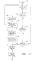
- FIG. 4 there is shown a flow chart illustrating the software operation for automatically generating the look-up tables associated with each color bar for each requested pattern.
- the system makes use of the RUN LIST generated by the operator at terminal 13 for producing the look-up tables for the requested pattern in the requested color combination.
- the system operates in four phases, the first three phases retrieve the file information and the machine color loading configuration necessary to produce the look-up tables for the requested pattern and the fourth phase actually generates the look-up tables to be used.
- the software system starts 42 by obtaining a RUN LIST entry 44 from the operator's RUN LIST. Next, the system determines the type of RUN LIST entry, i.e., Base entry, color entry, or SKU entry as indicated by steps 46, 52 and 58.
- the system retrieves the Base file for that entry and obtains the firing times for each color bar for the respective substrate base as shown in step 48. From the firing times, the system generates a firing time table for each color bar in the jet dyeing apparatus at step 50. Once the firing time table has been generated, the system loops back to retrieve the next RUN LIST entry.
- the system obtains the color loading indicated by the RUN LIST (step 54).
- the machine configuration color loading is determined by the operator depending upon which colors are loaded into the respective dye tanks 33 ( Figure 3) for each color bar 36 in the jet dyeing apparatus 18. From the color loading, a table of machine colors for the color bars is generated, as indicated by step 56, and the system then loops to obtain the next RUN LIST entry.
- the system obtains the data from the SKU file, stored elsewhere in the system, such as in the pattern computer 14 ( Figure 1) or optical disk storage (not shown). From the SKU file, a pattern color table is generated, step 61, containing the colors associated with each pixel code in the pattern. Once the firing time table, machine color table, and pattern color table have been generated for a respective job, then the final phase of actually generating the look-up table is performed as shown in the flow chart of Figure 5.
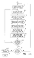
- the system automatically generates the look-up tables for each color bar for the respective pattern, step 66, by first obtaining a first pixel code from the pattern color table, as indicated at step 68. Next, at step 70, using the pixel code previously obtained, the first color and percent of color from the pattern color table are obtained. Using the color, the system next gets the color bar number associated with that color from the machine color table, step 72. From the color bar number, the system obtains the firing time for the respective color bar from the firing time table as indicated by step 78. At step 84, a modified firing time is obtained by multiplying the percent of color, obtained in step 70, and the firing time obtained in step 78. The modified firing time is then stored in the look-up table for the given pixel code and color bar number as indicated by step 86.
- step 88 determines whether all colors for the particular pixel code have been found. If not, the system loops back to step 70 wherein the next color and percent of color are obtained from the pattern color table for the particular pixel code. This loop, steps 70-88, continues to repeat until all of the colors for the particular pixel code have been found.
- the system determines whether all pixel codes have been loaded into the look-up table. If not, the system reverts to step 68 wherein the next pixel code is obtained from the pattern color table. The steps 68-90 then continue to loop until all pixel codes have been loaded into the look-up table. At this point, the entire look-up table for the requested pattern has been generated and is sent to the jet dyeing apparatus (step 92) before completing (step 94).
- the system software depicted by the flow charts shown in Figures 4 and 5 repeats itself each time new look-up tables are required. This may occur due to a change in the pattern to be printed, a change in the substrate or base upon which the pattern is to be printed or when the machine is configured differently. In this respect, it may be necessary to reconfigure the machine due to a malfunction of one or more of the color bars. For example, if the apparatus includes eight color bars, and only two colors are necessary for the pattern, if one of the color bars malfunctions, then that color can be loaded into one of the remaining six color bars and new look-up tables can be generated to still print the desired pattern.
- the system determines that the entry is a Base entry and obtains the firing times for Base WXYZ from the Base file (step 48).
- the system then generates the firing time table for each color bar as shown in Figure 6A wherein the firing times are given in milliseconds (ms).
- the next RUN LIST entry, "Color Bar 1 red”, is obtained and it is determined that it is for a color entry (step 52).
- the system obtains the color loading from the RUN LIST and generates the table of machine colors for the color bars as shown in Figure 6B. Each of the color entries in the RUN LIST is obtained to complete the machine color table.
- the system begins generating the actual look-up table for the requested pattern identified by SKU ABC.
- the first pixel code A and its associated color, red are obtained from the pattern color table.
- the system identifies the color red with color bar 1 from the machine color table.
- the firing time for color bar 1 is obtained from the firing time table.
- a firing time of 10 ms, associated with color bar 1 is stored in the look-up table shown in Figure 6D for the respective pixel code A.
- the system then repeats itself for pixel code B resulting in the storage of a 10 ms firing time for color bar 2 in the look-up table. Any look-up entry not filled by the system is assumed to contain a zero firing time or "null" firing time. Thus, the system generates the look-up tables shown in Figure 6D for the requested pattern ABC.
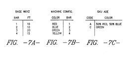
- Tables 7A-7C indicate the firing time table, machine color table and pattern color table, respectively, associated with SKU ADE.
- the firing time table shown in Figure 7A is identical to the previous example as the same Base WXYZ is being run through the apparatus.
- the machine color table remains the same as none of the color bar color loadings have been changed.
- the pattern color table differs from the preceding example because a new pattern, SKU ADE is being run.
- the SKU file associated with the pattern ADE for pixel code A, the associated colors include 50% red and 50% blue.
- steps 70-88 of Fig. 5 would loop twice, i.e., once for 50% red and a second time for the next color, 50% blue.
- the look-up tables shown in Fig. 7d are generated by the system.
- Pixel code A is first obtained from the pattern color table and its first color and percent of color, 50% red, are obtained (step 70).
- the system associates the color red with color bar number 1 and then obtains the firing time of 10 milliseconds for that color bar from the firing time table. This firing time, 10 milliseconds, is multiplied by the percent of the color to obtain the modified firing time.
- 10 milliseconds times 50% equals 5 milliseconds which is then stored in the look-up table for the given pixel code and color bar.
- step 70 (Fig. 5) and obtains the next color, i.e., 50% blue.
- This sequence of steps, 70-88, are repeated and the modified firing time stored in the look-up table (Fig. 7d). The operation then repeats for the remaining pixel codes in the pattern color table until the look-up tables are completed. It is apparent that by using percentages of colors, the colors can be shaded or blended to form other colors which are not loaded in the jet dying apparatus.
- the system automatically generates the look-up tables in response to the operators RUN LIST.
- the operator only needs to input the type of base to be run, the SKU pattern requested, and the machine configuration.
- the system then generates the look-up tables without any costly time delays for reloading colors in the color bars. Further, if one of the color bars malfunctions, the operator can still possibly finish the RUN LIST without any delays. For example, assuming a five color bar machine wherein only four of the color bars have been previously loaded as in the above examples. If, while preparing to run the pattern given by SKU ABC, the machine malfunctions and color bar 1 is no longer operative, then the operator can quickly load color bar 5 with the red color dye and the system will automatically generate new look-up tables in response thereto.
Landscapes
- Engineering & Computer Science (AREA)
- Chemical & Material Sciences (AREA)
- Materials Engineering (AREA)
- Textile Engineering (AREA)
- Treatment Of Fiber Materials (AREA)
- Coloring (AREA)
- Spectrometry And Color Measurement (AREA)
- Analysing Materials By The Use Of Radiation (AREA)
- Facsimile Image Signal Circuits (AREA)
- Image Generation (AREA)
Claims (27)
- Rechnergestütztes Verfahren zum Steuern der Aufbringung von Farbstoff auf ein Substrat in einer Textilfärbeanlage mit einem Prozessorsystem (10; 12; 16) und einem oder mehreren Farbbalken,
gekennzeichnet durch die Arbeitsschritte:a) Einlesen einer Eingabenliste (44; Tabelle C) mit einer Grundeingabe, Eingaben zur Maschinenfarbenladung und einer Materialeingabe in das Prozessorsystem (10; 12; 16);b) Erstellung einer Strahlzeittabelle (50; Fig. 6A; Fig. 7A) mit Strahlzeiten für jeden aus einer Vielzahl Farbbalken (36) in bezug auf einen bestimmten Grund, anhand der Grundeingabe;c) Erstellung einer Maschinenfarbentabelle (56; Fig. 6B; Fig. 7B) mit Farbendaten für jeden aus der Vielzahl Farbbalken (36), anhand der Eingaben zur Maschinenfarbenladung;d) Erstellung einer Musterfarbentabelle (Fig. 6C; Fig. 7C) mit Pixelcodes und den ihnen zugeordneten Farben in bezug auf ein bestimmtes Muster, anhand der Materialeingabe;e) Korrelation der Strahlzeiten, Farbendaten und Pixelcodes, derart, daß für jeden Pixelcode je Farbbalken eine zugehörige modifizierte Strahlzeit ermittelbar ist;f) Laden einer Nachschlagtabelle (Fig. 6D; Fig. 7D; Fig. 7E; Fig. 7F) mit den zugehörigen modifizierten Strahlzeitdaten für jeden Pixelcode je Farbbalken; undg) Verwendung der zugehörigen modifizierten Strahlzeiten für jeden Pixelcode je Farbbalken, derart, daß die Aufbringung von Farbstoff auf ein Substrat aus einer Farbstoffdüse am zugehörigen Farbbalken steuerbar ist. - Verfahren nach Anspruch 1,
bei dem der Schritt der Korrelation die Arbeitsschritte umfaßt:a) Ermittlungung eines Pixelcodes anhand der Musterfarbentabelle (68);b) Zuordnung des Pixelcodes zu einer Farbe und einem Farbenprozentsatz anhand der Musterfarbentabelle (70);c) Ermittlung eines der Farbe zugeordneten Farbbalkens in der Maschinenfarbentabelle (72);d) Ermittlung einer dem Farbbalken zugeordneten Strahlzeit in der Strahlzeittabelle (78);e) Bestimmung einer modifizierten Strahlzeit durch Multiplizieren dieser Strahlzeit mit dem Farbenprozentsatz aus der Musterfarbentabelle (84); undf) Wiederholung der Schritte (a), (b), (c), (d) und (e) für alle Farben und Farbenprozentsätze, die jedem Pixelcode in der Musterfarbentabelle zugeordnet sind. - Verfahren nach Anspruch 1 oder 2,
bei dem der Schritt der Erstellung einer Strahlzeittabelle (50) die Arbeitsschritte umfaßt:a) Zugriff auf eine Grunddatei, die der Grundeingabe in der Eingabenliste zugeordnet ist und die Strahlzeitdaten für jeden Farbbalken in der Anlage in bezug auf das vorgegebene Muster enthält; undb) Kompilierung der Strahlzeittabelle durch Zuordnen jedes Farbbalkens in der Anlage zu den Strahlzeitdaten. - Verfahren nach einem der vorhergehenden Ansprüche, bei dem der Schritt der Erstellung einer Maschinenfarbentabelle (56) die Arbeitsschritte umfaßt:a) Lesen der Farbenladungseingaben zur Bestimmung der Farbendaten für jeden der Farbbalken in der Anlage; undb) Kompilierung der Maschinenfarbentabelle durch Zuordnen jedes Farbendatenelementes zu dem mit dieser bestimmten Farbe versorgten Farbbalken.
- Verfahren nach einem der vorhergehenden Ansprüche, bei dem der Schritt der Erstellung einer Musterfarbentabelle die Arbeitsschritte umfaßt:a) Zugriff auf eine der Materialeingabe in der Eingabenliste zugeordnete Materialdatei, welche die dem vorgegebenen Muster zugeordneten Pixelcodes in der Materialdatei und die jedem der Pixelcodes zugeordneten Farben enthält; undb) Kompilierung der Musterfarbentabelle, die jedem Pixelcode seine zugehörigen Farben zuordnet, aus der Materialdatei.
- Verfahren nach einem der vorhergehenden Ansprüche, bei dem der Arbeitsschritt des Einlesens einer Eingabenliste von einem Benutzer ausgeführt wird, der Eingaben einliest, die dem Grund, der Materialdatei und der Maschinenfarbenladung, die für die Erzeugung eines geforderten Musters notwendig sind, entsprechen.
- Verfahren nach einem der vorhergehenden Ansprüche, bei dem in eine Vielzahl Nachschlagtabellen (Fig. 6D; Fig. 7D; Fig. 7E; Fig. 7F) die modifizierten Strahlzeitdaten für jeden Pixelcode je Farbbalken eingelesen werden, wobei die Nachschlagtabellen die Strahlzeiten für jede Farbstoffdüse in jedem Farbbalken für ein gefordertes Muster definieren.
- Verfahren nach einem der vorhergehenden Ansprüche, bei dem die Eingabenliste (Tabelle C), welche die Grundeingabe, die Eingaben zur Maschinenfarbenladung und die Materialeingabe enthält, in eine Rechnerdatenbank eingelesen wird, und das die weiteren Arbeitsschritte umfaßt:a) Anordnung einer Vielzahl Farbbalken (36), von denen jeder zugehörige Farbstoffdüsen entlang einer Bewegungsbahn eines textilen Substrats aufweist;b) Fortbewegung eines textilen Substrats entlang der Bewegungsbahn; undc) Betätigung der Farbstoffdüsen nach Strahlzeiten entsprechend den durch die Nachschlagtabellen zusammengestellten Daten.
- Rechnergestützte Textilfärbevorrichtung, mita) einer Vielzahl Farbbalken (36), die in einem Arbeitsbereich entlang der Bewegungsbahn eines Substrats (15) angeordnet sind;b) einer Vielzahl einzelner Farbstoffaufbringorgane, die mit Zwischenabstand entlang jedem der Farbbalken (36) angeordnet sind und einen Farbstoffstrom selektiv auf einen vorbestimmten Abschnitt des Substrats (15) zu strahlen vermögen;c) einem Prozessorsystem (10; 12; 16), das mit der Textilfärbevorrichtung zur Realisierung eines geforderten Musters gekoppelt ist,gekennzeichnet durch die Bereitstellung von:d) einer Einrichtung zum Einlesen einer Eingabenliste (Tabelle C) mit einer Grundeingabe, Eingaben zur Maschinenfarbenladung und einer Materialeingabe in das Prozessorsystem;e) einer Einrichtung zum Erstellen einer Strahlzeittabelle (Fig. 6A; Fig. 7A) von Strahlzeiten für jeden aus der Vielzahl der Farbbalken in bezug auf einen vorgegebenen Grund anhand der Grundeingabe;f) einer Einrichtung zum Erstellen einer Maschinenfarbentabelle (Fig. 6B; Fig. 7B) von Farbendaten für jeden aus der Vielzahl der Farbbalken, anhand der Eingaben zur Maschinenfarbenladung;g) einer Einrichtung zum Erstellen einer Musterfarbentabelle (Fig. 6C; Fig. 7C) von Pixelcodes und den ihnen in bezug auf ein bestimmtes Muster zugeordneten Farben anhand der Materialeingabe;h) einer Einrichtung zum Korrelieren der Strahlzeiten, Farbendaten und Pixelcodes, derart, daß eine modifizierte Strahlzeit für jeden Pixelcode je Farbbalken ermittelbar ist; undi) einer Einrichtung zum Laden einer Nachschlagtabelle (Fig. 6D; Fig. 7D; Fig. 7E; Fig. 7F) mit den modifizierten Strahlzeitdaten für jeden Pixelcode je Farbbalken.
- Vorrichtung nach Anspruch 9,
bei der die Einrichtung zum Korrelieren umfaßt:a) eine Einrichtung zur Ermittlung eines Pixelcodes anhand der Musterfarbentabelle (Fig. 6C; Fig. 7C);b) eine Einrichtung zum Zuordnen des Pixelcodes zu einer Farbe und zu einem Farbenprozentsatz anhand der Musterfarbentabelle;c) eine Einrichtung zur Ermittlung eines dieser Farbe zugeordneten Farbbalkens in der Maschinenfarbentabelle (Fig. 6B; Fig. 7B);d) eine Einrichtung zur Ermittlung einer dem Farbbalken zugeordneten Strahlzeit in der Strahlzeittabelle (Fig. 6A; Fig. 7A); unde) eine Einrichtung zum Bestimmen einer modifizierten Strahlzeit (Fig. 6D; Fig. 7D; Fig. 7E; Fig. 7F) durch Multiplizieren dieser Strahlzeit mit dem Farbenprozentsatz aus der Musterfarbentabelle. - Vorrichtung nach Anspruch 9 oder 10,
bei der die Einrichtung zum Erstellen einer Strahlzeittabelle umfaßt:a) eine Einrichtung zum Zugreifen auf eine Grunddatei, die der Grundeingabe in der Eingabenliste zugeordnet ist und die Strahlzeitdaten für jeden Farbbalken in der Anlage in bezug auf das vorgegebene Muster enthält; undb) eine Einrichtung zum Kompilieren einer Strahlzeittabelle durch Zuordnen jedes Farbbalkens in der Anlage zu den Strahlzeitdaten. - Vorrichtung nach einem der Ansprüche 9 bis 11, bei der die Einrichtung zum Erstellen einer Maschinenfarbentabelle umfaßt:a) eine Einrichtung zum Lesen der Farbenladungseingaben zur Bestimmung der Farbendaten für jeden der Farbbalken in der Anlage; undb) eine Einrichtung zum Kompilieren einer Maschinenfarbentabelle durch Zuordnen jedes Farbdatenelementes zu dem mit dieser bestimmten Farbe geladenen Farbbalken.
- Vorrichtung nach einem der Ansprüche 9 bis 12, bei der die Einrichtung zum Erstellen einer Musterfarbentabelle umfaßt:a) eine Einrichtung zum Zugreifen auf eine Materialdatei, die der Materialeingabe in der Eingabenliste zugeordnet ist und die dem vorgegebenen Muster zugeordneten Pixelcodes in der Materialdatei und die jedem der Pixelcodes zugeordneten Farben enthält; undb) eine Einrichtung zum Kompilieren einer Musterfarbentabelle, die jedem Pixelcode die ihm zugehörigen Farben anhand der Materialdatei zuordnet.
- Vorrichtung nach einem der Ansprüche 9 bis 13, mit einer Farbstoffverteiler-Baugruppe (39; 41), die sich über das Substrat erstreckt und die Farbbalken umfaßt.
- Vorrichtung nach Anspruch 14,
ferner mit einem Vorratstank (33) für flüssigen Farbstoff, der in Fluidverbindung mit der Verteiler-Baugruppe (39; 41) steht. - Vorrichtung nach Anspruch 15,
ferner mit Betätigungsgliedern zum Betätigen der Farbstoffaufbringorgane in der Weise, daß ein Farbstoffstrom selektiv auf einen vorbestimmten Abschnitt des Substrats (15) gestrahlt wird, wobei die Betätigungsglieder von einem Ventil (V) gesteuerte Luftablenker (62) für jedes Farbstoffaufbringorgan aufweisen, wobei die Einrichtungen zum Korrelieren der Strahlzeiten, Farbdaten und Pixelcodes zur Ermittlung einer modifizierten Strahlzeit (Fig. 6D; Fig. 7D; Fig. 7E; Fig. 7F) für jeden Pixelcode je Farbbalken (36) mit den Luftablenkern (62) zusammenwirken, derart, daß abhängig von empfangenen Musterinformationen der Luftstrom unterbrechbar ist. - Vorrichtung nach Anspruch 16,
bei der jedes Ventil (V) von einem durch ein elektrisches Signal betätigten elektromagnetischen Solenoid-Typ ist. - Vorrichtung nach Anspruch 17,
bei der die Einrichtung zum Bestimmen einer modifizierten Strahlzeit durch Multiplizieren der Strahlzeit mit dem Farbenprozentsatz aus der Musterfarbentabelle mit dem Solenoid elektrisch verbunden ist, derart, daß an es ein elektrisches Signal abgebbar ist, das der modifizierten Strahlzeit entspricht. - Vorrichtung nach einem der Ansprüche 16 bis 18,
bei der die Aufbringorgane eine Gruppe Farbstoffdüsen umfassen, und die Luftablenker (62) so angeordnet sind, daß sie Luft ständig an die Farbstoffdüsen blasen, um Farbstoff vom Substrat (15) weg abzulenken. - Vorrichtung nach einem der Ansprüche 9 bis 19,
bei der das Substrat (15) entlang einer endlosen Bewegungsbahn fortbewegt wird, und ferner mit einem Sensor (19) zum Erfassen von Bewegung des Substrats (15), der mit der Einrichtung zum Bestimmen der modifizierten Strahlzeiten integriert ist, um die Strahlzeit zur Anpassung an Bewegung des Substrats einzustellen. - Vorrichtung nach einem der Ansprüche 9 bis 20,
bei der das Prozessorsystem (10; 12; 16) einen Echtzeit-Rechner (10), einen Hauptrechner (12) aufweist, und bei der die Einrichtung zum Einlesen einer Eingabenliste ein Terminal (13) mit Eingabetasten umfaßt. - Vorrichtung nach Anspruch 21,
bei der der Rechner (10; 12) eine Einrichtung zur Bereitstellung von Befehlen für das Auslesen einer SKU-Datei und einer Grunddatei mit den erforderlichen Musterinformationen umfaßt. - Vorrichtung nach Anspruch 21 oder 22,
bei der der Rechner (10; 12) eine Quelle zum Speichern von Musterdaten aufweist, wobei der Hauptrechner (12) Einrichtungen zum Abrufen der Musterdaten aus der Quelle umfaßt. - Vorrichtung nach Anspruch 23,
bei der die Quelle für Musterdaten ein Musterrechner (14) ist. - Vorrichtung nach einem der Ansprüche 9 bis 24,
bei der die Vielzahl Farbbalken (36) acht Farbbalken umfaßt, von denen jeder mehr als 100 Farbstoffdüsen aufweist. - Vorrichtung nach einem der Ansprüche 9 bis 25,
ferner mit einem Echtzeit-Rechner (10) zum Sicherstellen, daß Musterrohdaten aus der Quelle an das Mustersteuersystem (16) ordnungsgemäß ausgegeben werden. - Vorrichtung nach einem der Ansprüche 20 bis 26,
bei der die Einrichtung zum Erfassen von Bewegung des Substrats ein Drehbewegungs-Meßgrößenumformer (19) ist, der mit dem Mustersteuersystem (16) elektrisch verbunden ist.
Applications Claiming Priority (2)
| Application Number | Priority Date | Filing Date | Title |
|---|---|---|---|
| US488564 | 1983-04-25 | ||
| US07/488,564 US5195043A (en) | 1990-03-02 | 1990-03-02 | Automatic generation of look-up tables for requested patterns and colors |
Publications (2)
| Publication Number | Publication Date |
|---|---|
| EP0448215A1 EP0448215A1 (de) | 1991-09-25 |
| EP0448215B1 true EP0448215B1 (de) | 1996-08-21 |
Family
ID=23940168
Family Applications (1)
| Application Number | Title | Priority Date | Filing Date |
|---|---|---|---|
| EP91301117A Expired - Lifetime EP0448215B1 (de) | 1990-03-02 | 1991-02-12 | Verfahren und Vorrichtung zur Überwachung eines Färbprozesses |
Country Status (9)
| Country | Link |
|---|---|
| US (1) | US5195043A (de) |
| EP (1) | EP0448215B1 (de) |
| JP (1) | JP3184547B2 (de) |
| AT (1) | ATE141659T1 (de) |
| AU (1) | AU634859B2 (de) |
| CA (1) | CA2036231C (de) |
| DE (1) | DE69121438T2 (de) |
| DK (1) | DK0448215T3 (de) |
| NZ (1) | NZ237253A (de) |
Families Citing this family (16)
| Publication number | Priority date | Publication date | Assignee | Title |
|---|---|---|---|---|
| DE4012905A1 (de) * | 1990-04-23 | 1991-10-24 | Linotype Ag | Verfahren und vorrichtung zur erzeugung einer digitalen drucktabelle fuer druckfarben bei bildreproduktionsgeraeten |
| US5540518A (en) * | 1993-09-29 | 1996-07-30 | Linear Dynamics Inc. | Method and apparatus for controlling striping equipment |
| AU2594595A (en) * | 1994-05-16 | 1995-12-05 | Apple Computer, Inc. | Pattern and color abstraction in a graphical user interface |
| JP2998671B2 (ja) * | 1997-01-10 | 2000-01-11 | ウペポ・アンド・マジ株式会社 | 服飾のデザイン及び製作の支援方法 |
| US6509979B2 (en) | 1997-04-03 | 2003-01-21 | Milliken & Company | Printing method using inter-pixel blending on an absorbent substrate |
| US6342952B1 (en) * | 1999-10-11 | 2002-01-29 | Flint Ink Corporation | Method for matching printing ink colors |
| US7418407B2 (en) * | 1999-10-14 | 2008-08-26 | Jarbridge, Inc. | Method for electronic gifting using merging images |
| US7268918B2 (en) | 2001-08-16 | 2007-09-11 | Sun Chemical Corporation | System and method for controlling metamerism |
| US7417764B2 (en) * | 2001-08-16 | 2008-08-26 | Sun Chemical Corporation | System and method for disseminating color ink and colorant formulas |
| US7034960B2 (en) * | 2001-08-16 | 2006-04-25 | Sun Chemical Corporation | System and method for managing electronic transmission of color data |
| EP1306474A1 (de) * | 2001-10-23 | 2003-05-02 | Viktor Achter GmbH & Co KG | Flache leichte Geweben und deren Verwendung zur Herstellung von Sitzüberzügen |
| US7072733B2 (en) * | 2002-01-22 | 2006-07-04 | Milliken & Company | Interactive system and method for design, customization and manufacture of decorative textile substrates |
| WO2005074552A2 (en) * | 2004-01-30 | 2005-08-18 | Milliken & Company | Digital control system |
| US20060170970A1 (en) * | 2005-01-28 | 2006-08-03 | Chris Tuijn | Method for defining an imposition plan |
| US8145345B2 (en) | 2006-04-24 | 2012-03-27 | Milliken & Company | Automated pattern generation processes |
| US8155776B2 (en) | 2007-05-22 | 2012-04-10 | Milliken & Company | Automated randomized pattern generation using pre-defined design overlays and products produced thereby |
Family Cites Families (8)
| Publication number | Priority date | Publication date | Assignee | Title |
|---|---|---|---|---|
| US3894413A (en) * | 1974-01-03 | 1975-07-15 | Deering Milliken Res Corp | Dyeing and printing of materials |
| US4033154A (en) * | 1974-06-07 | 1977-07-05 | Deering Milliken Research Corporation | Electronic control system for dyeing and printing materials |
| US4116626A (en) * | 1976-05-17 | 1978-09-26 | Milliken Research Corporation | Printing of pattern designs with computer controlled pattern dyeing device |
| US4545086A (en) * | 1976-05-17 | 1985-10-08 | Milliken Research Corporation | Pattern designs printed with computer controlled pattern dyeing device |
| US4170883A (en) * | 1976-05-17 | 1979-10-16 | Milliken Research Corporation | Printing of pattern designs with computer controlled pattern dyeing device |
| US4614300A (en) * | 1982-04-19 | 1986-09-30 | E. I. Du Pont De Nemours And Company | Computerized spray machine |
| EP0306568A1 (de) * | 1987-09-07 | 1989-03-15 | Dawson Ellis Limited | Vorrichtung und Verfahren zum Aufbringen von Behandlungsflüssigkeit auf eine Materialbahn |
| US4984169A (en) * | 1989-03-23 | 1991-01-08 | Milliken Research Corp. | Data loading and distributing process and apparatus for control of a patterning process |
-
1990
- 1990-03-02 US US07/488,564 patent/US5195043A/en not_active Expired - Lifetime
-
1991
- 1991-02-12 AT AT91301117T patent/ATE141659T1/de not_active IP Right Cessation
- 1991-02-12 EP EP91301117A patent/EP0448215B1/de not_active Expired - Lifetime
- 1991-02-12 DE DE69121438T patent/DE69121438T2/de not_active Expired - Fee Related
- 1991-02-12 DK DK91301117.7T patent/DK0448215T3/da active
- 1991-02-14 CA CA002036231A patent/CA2036231C/en not_active Expired - Fee Related
- 1991-02-18 AU AU71119/91A patent/AU634859B2/en not_active Ceased
- 1991-02-27 NZ NZ237253A patent/NZ237253A/en unknown
- 1991-02-28 JP JP05958691A patent/JP3184547B2/ja not_active Expired - Fee Related
Also Published As
| Publication number | Publication date |
|---|---|
| JP3184547B2 (ja) | 2001-07-09 |
| AU7111991A (en) | 1991-09-05 |
| US5195043A (en) | 1993-03-16 |
| JPH04214462A (ja) | 1992-08-05 |
| EP0448215A1 (de) | 1991-09-25 |
| ATE141659T1 (de) | 1996-09-15 |
| DK0448215T3 (de) | 1997-02-10 |
| NZ237253A (en) | 1994-12-22 |
| DE69121438T2 (de) | 1997-03-27 |
| CA2036231A1 (en) | 1991-09-03 |
| AU634859B2 (en) | 1993-03-04 |
| DE69121438D1 (de) | 1996-09-26 |
| CA2036231C (en) | 2000-04-04 |
Similar Documents
| Publication | Publication Date | Title |
|---|---|---|
| EP0448215B1 (de) | Verfahren und Vorrichtung zur Überwachung eines Färbprozesses | |
| EP0389109B1 (de) | Einrichtung zur Überwachung eines Färbeverfahrens | |
| EP0449410B1 (de) | Kontrolleinrichtung für eine Färbdüsenvorrichtung | |
| US6792329B2 (en) | Construction of colored images on absorbent substrates using a computer-aided design system | |
| EP1419473B1 (de) | Reproduktion von farbbildern auf absorbierenden substraten mit farbmischtechniken | |
| NZ237255A (en) | Distributing dye pattern data using memory access controller | |
| US3939675A (en) | Apparatus for dyeing and printing materials having improved means for support thereof | |
| JP2023178041A (ja) | 刺繍システム | |
| CN111098591A (zh) | 用于对印刷机中的页张进行施粉的方法和设备 | |
| JPS6144984B2 (de) | ||
| US5228161A (en) | Method for continuously printing polychromatic designs, especially on fabrics and the like, and device for its realization | |
| JPH0359161A (ja) | 織物糸の連続染色用装置 | |
| CA2036369C (en) | System for the real-time scheduling and loading of look-up tables for a patterning device | |
| AU651325B2 (en) | Method and apparatus for delivering metered quantities of fluid | |
| CA1073233A (en) | Electromagnetic valve array in jet dyeing apparatus |
Legal Events
| Date | Code | Title | Description |
|---|---|---|---|
| PUAI | Public reference made under article 153(3) epc to a published international application that has entered the european phase |
Free format text: ORIGINAL CODE: 0009012 |
|
| AK | Designated contracting states |
Kind code of ref document: A1 Designated state(s): AT BE CH DE DK ES FR GB GR IT LI LU NL SE |
|
| 17P | Request for examination filed |
Effective date: 19910906 |
|
| 17Q | First examination report despatched |
Effective date: 19940620 |
|
| GRAH | Despatch of communication of intention to grant a patent |
Free format text: ORIGINAL CODE: EPIDOS IGRA |
|
| GRAA | (expected) grant |
Free format text: ORIGINAL CODE: 0009210 |
|
| GRAH | Despatch of communication of intention to grant a patent |
Free format text: ORIGINAL CODE: EPIDOS IGRA |
|
| AK | Designated contracting states |
Kind code of ref document: B1 Designated state(s): AT BE CH DE DK ES FR GB GR IT LI LU NL SE |
|
| PG25 | Lapsed in a contracting state [announced via postgrant information from national office to epo] |
Ref country code: FR Effective date: 19960821 Ref country code: GR Free format text: LAPSE BECAUSE OF FAILURE TO SUBMIT A TRANSLATION OF THE DESCRIPTION OR TO PAY THE FEE WITHIN THE PRESCRIBED TIME-LIMIT Effective date: 19960821 Ref country code: AT Effective date: 19960821 Ref country code: ES Free format text: THE PATENT HAS BEEN ANNULLED BY A DECISION OF A NATIONAL AUTHORITY Effective date: 19960821 Ref country code: CH Effective date: 19960821 Ref country code: LI Effective date: 19960821 Ref country code: IT Free format text: LAPSE BECAUSE OF FAILURE TO SUBMIT A TRANSLATION OF THE DESCRIPTION OR TO PAY THE FEE WITHIN THE PRESCRIBED TIME-LIMIT;WARNING: LAPSES OF ITALIAN PATENTS WITH EFFECTIVE DATE BEFORE 2007 MAY HAVE OCCURRED AT ANY TIME BEFORE 2007. THE CORRECT EFFECTIVE DATE MAY BE DIFFERENT FROM THE ONE RECORDED. Effective date: 19960821 |
|
| REF | Corresponds to: |
Ref document number: 141659 Country of ref document: AT Date of ref document: 19960915 Kind code of ref document: T |
|
| REF | Corresponds to: |
Ref document number: 69121438 Country of ref document: DE Date of ref document: 19960926 |
|
| PG25 | Lapsed in a contracting state [announced via postgrant information from national office to epo] |
Ref country code: SE Effective date: 19961121 |
|
| EN | Fr: translation not filed | ||
| REG | Reference to a national code |
Ref country code: DK Ref legal event code: T3 |
|
| PG25 | Lapsed in a contracting state [announced via postgrant information from national office to epo] |
Ref country code: LU Free format text: LAPSE BECAUSE OF NON-PAYMENT OF DUE FEES Effective date: 19970228 |
|
| REG | Reference to a national code |
Ref country code: CH Ref legal event code: PL |
|
| PLBE | No opposition filed within time limit |
Free format text: ORIGINAL CODE: 0009261 |
|
| STAA | Information on the status of an ep patent application or granted ep patent |
Free format text: STATUS: NO OPPOSITION FILED WITHIN TIME LIMIT |
|
| 26N | No opposition filed | ||
| REG | Reference to a national code |
Ref country code: GB Ref legal event code: 732E |
|
| NLS | Nl: assignments of ep-patents |
Owner name: MILLIKEN & COMPANY |
|
| REG | Reference to a national code |
Ref country code: GB Ref legal event code: IF02 |
|
| PGFP | Annual fee paid to national office [announced via postgrant information from national office to epo] |
Ref country code: DE Payment date: 20060331 Year of fee payment: 16 |
|
| PGFP | Annual fee paid to national office [announced via postgrant information from national office to epo] |
Ref country code: NL Payment date: 20070222 Year of fee payment: 17 |
|
| PG25 | Lapsed in a contracting state [announced via postgrant information from national office to epo] |
Ref country code: DE Free format text: LAPSE BECAUSE OF NON-PAYMENT OF DUE FEES Effective date: 20070901 |
|
| PGFP | Annual fee paid to national office [announced via postgrant information from national office to epo] |
Ref country code: DK Payment date: 20080228 Year of fee payment: 18 |
|
| PGFP | Annual fee paid to national office [announced via postgrant information from national office to epo] |
Ref country code: GB Payment date: 20080227 Year of fee payment: 18 |
|
| PGFP | Annual fee paid to national office [announced via postgrant information from national office to epo] |
Ref country code: BE Payment date: 20080306 Year of fee payment: 18 |
|
| NLV4 | Nl: lapsed or anulled due to non-payment of the annual fee |
Effective date: 20080901 |
|
| PG25 | Lapsed in a contracting state [announced via postgrant information from national office to epo] |
Ref country code: NL Free format text: LAPSE BECAUSE OF NON-PAYMENT OF DUE FEES Effective date: 20080901 |
|
| BERE | Be: lapsed |
Owner name: *MILLIKEN & CY UNE SOC. DE L'ETAT DE DELAWARE Effective date: 20090228 |
|
| REG | Reference to a national code |
Ref country code: DK Ref legal event code: EBP |
|
| GBPC | Gb: european patent ceased through non-payment of renewal fee |
Effective date: 20090212 |
|
| PG25 | Lapsed in a contracting state [announced via postgrant information from national office to epo] |
Ref country code: BE Free format text: LAPSE BECAUSE OF NON-PAYMENT OF DUE FEES Effective date: 20090228 |
|
| PG25 | Lapsed in a contracting state [announced via postgrant information from national office to epo] |
Ref country code: GB Free format text: LAPSE BECAUSE OF NON-PAYMENT OF DUE FEES Effective date: 20090212 |
|
| PG25 | Lapsed in a contracting state [announced via postgrant information from national office to epo] |
Ref country code: DK Free format text: LAPSE BECAUSE OF NON-PAYMENT OF DUE FEES Effective date: 20090831 |