EP0448306A2 - SchraubenschlÀ¼ssel - Google Patents
SchraubenschlÀ¼ssel Download PDFInfo
- Publication number
- EP0448306A2 EP0448306A2 EP91302241A EP91302241A EP0448306A2 EP 0448306 A2 EP0448306 A2 EP 0448306A2 EP 91302241 A EP91302241 A EP 91302241A EP 91302241 A EP91302241 A EP 91302241A EP 0448306 A2 EP0448306 A2 EP 0448306A2
- Authority
- EP
- European Patent Office
- Prior art keywords
- socket
- reaction
- body portion
- torque wrench
- arm
- Prior art date
- Legal status (The legal status is an assumption and is not a legal conclusion. Google has not performed a legal analysis and makes no representation as to the accuracy of the status listed.)
- Granted
Links
Images


Classifications
-
- B—PERFORMING OPERATIONS; TRANSPORTING
- B25—HAND TOOLS; PORTABLE POWER-DRIVEN TOOLS; MANIPULATORS
- B25B—TOOLS OR BENCH DEVICES NOT OTHERWISE PROVIDED FOR, FOR FASTENING, CONNECTING, DISENGAGING, OR HOLDING
- B25B21/00—Portable power-driven screw or nut setting or loosening tools; Attachments for drilling apparatus serving the same purpose
- B25B21/004—Portable power-driven screw or nut setting or loosening tools; Attachments for drilling apparatus serving the same purpose of the ratchet type
- B25B21/005—Portable power-driven screw or nut setting or loosening tools; Attachments for drilling apparatus serving the same purpose of the ratchet type driven by a radially acting hydraulic or pneumatic piston
-
- B—PERFORMING OPERATIONS; TRANSPORTING
- B25—HAND TOOLS; PORTABLE POWER-DRIVEN TOOLS; MANIPULATORS
- B25B—TOOLS OR BENCH DEVICES NOT OTHERWISE PROVIDED FOR, FOR FASTENING, CONNECTING, DISENGAGING, OR HOLDING
- B25B23/00—Details of, or accessories for, spanners, wrenches, screwdrivers
- B25B23/0078—Reaction arms
Definitions
- This invention relates to torque wrenches and more particularly to such wrenches incorporating reaction members for engagement with a fixed component during the tightening or untightening procedure.
- the wrench When torque tightening a nut or a bolt of a series of nuts and bolts using a torque wrench provided with a reaction member, whether an arm or a foot, the wrench can usually be positioned whereby the reaction member reacts from the nut or bolt to either side of the one being tightened - i.e. the wrench can be located either behind or in front of the row of nuts and bolts.
- a torque wrench comprising an elongate body portion including a hydraulic piston-cylinder assembly, and a drive mechanism actuated by said assembly to rotate an associated component about a first axis extending perpendicular to the line of action of the piston-cylinder assembly, characterised by a reaction member mounted to the body portion to be pivotal relative thereto about a second axis extending parallel with the first axis between different positions extending angularly outwardly of the body portion.
- the pivotal reaction member of the torque wrench of the invention can be manoeuvred to ensure reaction against a suitable fixed component whereby said otherwise inaccessible nuts or bolts can be rotated.
- the body portion may house therein a separate hydraulic piston-cylinder assembly or the body portion may comprise the cylinder of the hydraulic piston-cylinder assembly.
- the reaction member includes, at or adjacent its free end remote from the pivotal mounting, a first socket adapted to locate over a first fixed component spaced from said component to be rotated.
- the reaction member may further include, intermediate said first socket and said pivotal mounting, one or more further sockets adapted to locate over further fixed components between said first fixed component and the component to be rotated.
- the reaction member comprises first and second arm portions extending longitudinally of the body portion one to each side of the pivotal mounting, each arm portion including, at or adjacent its free end remote from the pivotal mounting, a socket, the reaction member being pivotal between a first position in which, in use, the socket at or adjacent the free end of the first arm portion is located over a fixed component and the socket at or adjacent the free end of the second arm portion is located over the component to be rotated, and a second position in which, in use, the socket at or adjacent the free end of the second arm portion is located over a fixed component and the socket at or adjacent the free end of the first arm portion is located over the component to be rotated.
- the reaction arm may be mounted directly to the body portion and may comprise opposed, interconnected plates one to each side of the body portion and each including aligned sockets therein.
- the torque wrench may include a reaction foot removably mounted on the body portion, the reaction member comprising an arm pivotally mounted on said reaction foot.
- a torque wrench of relatively conventional construction including a generally cylindrical body portion 2 housing a hydraulic piston-cylinder assembly.
- a housing 4 containing a drive mechanism which, in the case of a conventional wrench, comprises a pivotal drive lever carrying a square drive shaft and to which can be attached sockets of varying sizes, all in conventional manner.
- reaction arms and/or reaction feet adapted to react against a fixed member, conveniently an adjacent nut or bolt head, during a tightening procedure.
- reaction arms and/or feet once mounted on the wrench, are fixed relative thereto and project therefrom in a given direction.
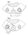
- FIGs. 1 and 2 there are shown three bolts A, B and C with access thereto restricted to the rear side thereof in the region referenced X.
- bolt A With a conventional wrench having a fixed reaction arm projecting therefrom, bolt A can be tightened by positioning the wrench in front of the row and with the reaction arm reacting against bolt B.
- bolt B can be tightened by the conventional wrench with the reaction arm reacting against bolt C.
- bolt C cannot be tightened because there is no abutment for the reaction arm of the wrench, which wrench cannot be located to the rear of the row to utilise bolt B as a reaction point because of the restricted access indicated at X.
- the wrench of the invention as shown in Figs. 1 and 2 includes a reaction arm 6 which is pivotally mounted to the body portion 2 to be movable between angularly-displaced positions extending outwardly from the body portion 2 to each side thereof.
- a suitable socket is attached to the square drive shaft of the wrench for location on the bolt B, while the free end of the pivotal reaction arm 6 incorporates a socket adapted to seat over the bolt C.
- the socket on the drive shaft is positioned on bolt B and the reaction arm 6 is pivoted so that the socket therein overlies and can be positioned on bolt C.
- the wrench is then actuated to tighten bolt B with the reaction being absorbed by bolt C via reaction arm 6.
- Bolt B can similarly be tightened by the wrench with reaction taking place against bolt A.
- the wrench is positioned as shown with the socket on the drive shaft again located on bolt B, but with the reaction arm 6 suitably pivoted relative to the body portion 2 so that the socket therein can be positioned on bolt A. Even in this position of the wrench, there is no impingement upon the region of restricted access at X.
- reaction arm 2 enables endmost nuts or bolts to be tightened providing there is a suitable reaction point to one side only of the nut or bolt to be tightened and regardless of which side that reaction point is located.
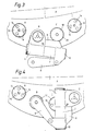
- Figs. 3 and 4 show an alternative torque wrench according to the invention which includes a reaction foot 8 mounted on the body portion 2, for example by means of a series of internal splines formed longitudinally of a hollow cylindrical bore through a member 10 carrying the reaction foot 8 and co-operating with a corresponding series of longitudinal splines formed along the body portion 2 of the wrench.
- reaction arm 6 Pivotally mounted to the member 10 is a reaction arm 6 the free end of which is adapted to carry a socket as will be detailed below.
- the bolts include heads 12 which are sunk into the member 14 so that the upper faces thereof are substantially flush with the surface of the member 14.
- Each bolt head 12 is provided with three uniformly-spaced bores 16 to receive therein corresponding pegs on an associated drive socket to be attached to the drive mechanism of the wrench.
- the illustrated wrench is of the low profile type and includes a drive lever with a hexagonal socket therein.
- the drive socket includes a hexagonal shaft one end of which is received in said socket in the drive lever and the other end of which carries said axially-extending pegs.
- Bolts A, B and C can be tightened by the wrench in its conventional mode and using the reaction foot 8.
- the drive socket is shown applied to the bolt B, while a peg reaction socket 18 similar to the drive socket and surrounded by a protective collar 20 is located on the head 12 of the bolt C for engagement by the reaction foot 8.
- the reaction arm 6 is not in use in this mode.
- bolt A can be tightened with the reaction foot 8 reacting on bolt B
- bolt C can be tightened with the reaction foot 8 reacting on bolt D.
- a peg drive socket is again mounted on the drive mechanism of the wrench for location on the bolt D, while a peg reaction socket is mounted to the free end of the reaction arm 6 to extend perpendicularly therefrom.
- the reaction socket is located on bolt B with the wrench positioned as shown in Fig. 4 and the reaction arm 6 extending angularly outwardly therefrom.
- the reaction foot 8 is not in use in this mode.
- bolt D can be tightened by reaction against bolt B and without the wrench impinging upon the region X of restricted access.
- Figs. 5 and 6 illustrate a low profile torque wrench according to the invention able to accommodate upward movement of a bolt on untightening thereof.
- the wrench is shown unfastening a bolt 20 by means of a peg drive socket 22 mounted to the drive mechanism of the wrench, with the pivotal reaction arm 6 carrying a peg reaction socket 24 located on a fixed bolt 26.
- the reaction socket 24 includes an upstanding cylindrical shaft 28 which extends through a corresponding bore in the reaction arm 6 whereby the arm 6 can slide along said shaft 28 between extreme positions determined by abutment with the top of the socket 24 and with an increased-diameter stop 30 on the free end of the shaft 28.
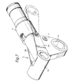
- Fig. 7 illustrates a low profile torque wrench according to the invention in which the reaction arm is so arranged as to eliminate the requirement for a reaction foot.
- the wrench includes a housing 4 containing a pivotal drive lever in which is formed a hexagonal socket 32, the reaction arm 6 being mounted to the body portion 2 to be pivotal about an axis extending parallel with the axis of rotation of the socket 32.
- the reaction arm 6 includes a pair of opposed plates 6 a , 6 b , one to each side of the wrench, the free ends of the arms 6 a , 6 b carrying a cylindrical socket 34.
- the configuration of the reaction arm 6 is such that it can pivot from the position shown in dotted lines in Fig. 7, just below the body portion 2, over the housing 4 to the position shown in full lines in Fig. 7 and thence, if required, to a position just above the body portion 2 with the socket 34 abutting the rear regions of the body portion 2 remote from the housing 4.
- Clearly such extensive angular movement of the reaction arm 6, together with the ability of the socket 34 to receive in either end thereof a fixed component enables this low profile wrench to react to either side of a bolt being tightened or slackened.
- FIG. 8 there is illustrated a development of the low profile torque wrench shown in Fig. 7 in which the reaction arm 6 again comprises opposed, interconnected plates 6 a , 6 b one to each side of the wrench.
- Each plate 6 a , 6 b includes a first arm portion 36, as in the embodiment of Fig. 7, together with a second arm portion 38 integral with the arm portion 36 and extending axially of the body portion 2 to the other side of the pivotal mounting of the reaction arm 6.
- the arm portions 38 are substantially mirror images of the associated arm portions 36, each portion 36 including a cylindrical socket 34 adjacent its free end and each portion 38 including a cylindrical socket 40 adjacent its free end.
- the arrangement is such that, in a first operative position of the torque wrench, the socket 34 locates over the fixed reaction component spaced to one side of the nut or bolt to be tightened, while the socket 40 locates over the socket actually used to tighten the nut or bolt in question.
- the socket 40 provides additional restraint for absorbing reaction forces.
- the reaction arm 6 is pivoted to the second operative position shown in Fig. 8 in which the socket 34 locates over the component to be tightened, while the socket 40 locates over the fixed component to the other side of the nut or bolt to be tightened.
- the reaction arm 6 shown in Fig. 8 is provided with additional apertures or sockets 42 therein intermediate the sockets 34 and 40 which may be of different sizes.
- additional sockets 42 can be located over additional or other fixed components thereby increasing the versatility of the tool and enabling different bolt pitches and/or different bolt sizes to be accommodated by a single tool.
- reaction arms 6 shown in the other drawings could also include additional sockets such as those shown at 42 in Fig. 8.
- torque wrenches of relatively simple construction which are capable of accommodating restricted access to nuts and bolts to be tightened or slackened but which can also be used in conventional situations for all pitch variations in the nuts and bolts.
Landscapes
- Engineering & Computer Science (AREA)
- Mechanical Engineering (AREA)
- Details Of Spanners, Wrenches, And Screw Drivers And Accessories (AREA)
- Drilling Tools (AREA)
Applications Claiming Priority (2)
| Application Number | Priority Date | Filing Date | Title |
|---|---|---|---|
| GB909006268A GB9006268D0 (en) | 1990-03-20 | 1990-03-20 | Improved torque wrench |
| GB9006268 | 1990-03-20 |
Publications (3)
| Publication Number | Publication Date |
|---|---|
| EP0448306A2 true EP0448306A2 (de) | 1991-09-25 |
| EP0448306A3 EP0448306A3 (en) | 1992-03-04 |
| EP0448306B1 EP0448306B1 (de) | 1995-01-18 |
Family
ID=10672937
Family Applications (1)
| Application Number | Title | Priority Date | Filing Date |
|---|---|---|---|
| EP91302241A Expired - Lifetime EP0448306B1 (de) | 1990-03-20 | 1991-03-15 | Schraubenschlüssel |
Country Status (9)
| Country | Link |
|---|---|
| US (1) | US5142951A (de) |
| EP (1) | EP0448306B1 (de) |
| AT (1) | ATE117235T1 (de) |
| CA (1) | CA2038694A1 (de) |
| DE (1) | DE69106754T2 (de) |
| DK (1) | DK0448306T3 (de) |
| ES (1) | ES2068499T3 (de) |
| GB (1) | GB9006268D0 (de) |
| GR (1) | GR3015730T3 (de) |
Cited By (1)
| Publication number | Priority date | Publication date | Assignee | Title |
|---|---|---|---|---|
| WO2011060453A1 (en) * | 2009-11-16 | 2011-05-19 | HYTORC Division Unex Corporation | Apparatus for tightening or loosening fasteners |
Families Citing this family (11)
| Publication number | Priority date | Publication date | Assignee | Title |
|---|---|---|---|---|
| USD333076S (en) | 1990-09-13 | 1993-02-09 | Makita Electric Works, Ltd. | Portable electric wrench |
| US6029546A (en) * | 1997-06-13 | 2000-02-29 | Parker-Hannifin Corporation | Reaction member system for rotary fluid-operated wrenches |
| USD473435S1 (en) | 2002-08-08 | 2003-04-22 | Bradford C. Stahl | Propeller nut wrench |
| FR2858783B1 (fr) * | 2003-08-13 | 2006-11-24 | Airbus France | Outil de serrage/desserrage d'organes visses |
| US7261018B2 (en) * | 2005-11-14 | 2007-08-28 | Jetyd Corp. | Power tool |
| US7451672B2 (en) * | 2006-01-11 | 2008-11-18 | Jetyd Corp. | Link attachment to torque wrench |
| US7765895B2 (en) * | 2007-10-29 | 2010-08-03 | Junkers John K | Fluid-operated torque wrench for and method of tightening or loosening fasteners |
| US20100270048A1 (en) * | 2009-04-22 | 2010-10-28 | Junkers John K | Reaction adaptors for torque power tools and methods of using the same |
| EP2421679B1 (de) | 2009-04-22 | 2015-10-21 | Hytorc Div. Unex Corporation | Vorrichtung zum anziehen oder lockern von befestigungsvorrichtungen |
| JP2015168020A (ja) * | 2014-03-06 | 2015-09-28 | 株式会社ユタニ | 反力受け装置 |
| USD1042067S1 (en) * | 2023-02-28 | 2024-09-17 | Primesource Consulting Llc | Limited clearance tool |
Family Cites Families (5)
| Publication number | Priority date | Publication date | Assignee | Title |
|---|---|---|---|---|
| US4269088A (en) * | 1979-09-14 | 1981-05-26 | N-S-W Corporation | Wrench tools for castellated nuts |
| US4385533A (en) * | 1981-08-28 | 1983-05-31 | Collins Bobby W | Universal reaction plate |
| US4480510A (en) * | 1981-09-28 | 1984-11-06 | Gratec, Inc. | Powered ratchet wrench |
| US4513645A (en) * | 1982-01-07 | 1985-04-30 | Bosko Grabovac | Hydraulic wrench |
| US4429597A (en) * | 1982-01-08 | 1984-02-07 | Consolidated Devices, Inc. | Hydraulic torque wrench |
-
1990
- 1990-03-20 GB GB909006268A patent/GB9006268D0/en active Pending
-
1991
- 1991-03-15 DK DK91302241.4T patent/DK0448306T3/da active
- 1991-03-15 DE DE69106754T patent/DE69106754T2/de not_active Expired - Fee Related
- 1991-03-15 AT AT91302241T patent/ATE117235T1/de not_active IP Right Cessation
- 1991-03-15 ES ES91302241T patent/ES2068499T3/es not_active Expired - Lifetime
- 1991-03-15 EP EP91302241A patent/EP0448306B1/de not_active Expired - Lifetime
- 1991-03-19 US US07/672,028 patent/US5142951A/en not_active Expired - Fee Related
- 1991-03-20 CA CA002038694A patent/CA2038694A1/en not_active Abandoned
-
1995
- 1995-04-10 GR GR950400863T patent/GR3015730T3/el unknown
Cited By (1)
| Publication number | Priority date | Publication date | Assignee | Title |
|---|---|---|---|---|
| WO2011060453A1 (en) * | 2009-11-16 | 2011-05-19 | HYTORC Division Unex Corporation | Apparatus for tightening or loosening fasteners |
Also Published As
| Publication number | Publication date |
|---|---|
| GR3015730T3 (en) | 1995-07-31 |
| EP0448306A3 (en) | 1992-03-04 |
| CA2038694A1 (en) | 1991-09-21 |
| GB9006268D0 (en) | 1990-05-16 |
| DE69106754D1 (de) | 1995-03-02 |
| US5142951A (en) | 1992-09-01 |
| DK0448306T3 (da) | 1995-06-06 |
| DE69106754T2 (de) | 1995-06-29 |
| ATE117235T1 (de) | 1995-02-15 |
| ES2068499T3 (es) | 1995-04-16 |
| EP0448306B1 (de) | 1995-01-18 |
Similar Documents
| Publication | Publication Date | Title |
|---|---|---|
| US5142951A (en) | Torque wrench | |
| EP0640444B1 (de) | Kompakter faltbarer Schraubenschlüssel | |
| EP1063060B1 (de) | Angetriebenes Werkzeug | |
| KR940011353B1 (ko) | 유체작동형 렌치 | |
| EP2082840A2 (de) | Werkzeug mit Sicherheitsdrehmomentverstärkung | |
| US6308423B1 (en) | Cutting tool with an improved guide repositioning structure | |
| EA013764B1 (ru) | Гаечный ключ с регулируемым крутящим моментом и гидравлическим приводом для затягивания или ослабления соединительных деталей и способ затягивания или ослабления соединительных деталей | |
| EA024183B1 (ru) | Устройство для затягивания или ослабления резьбовых креплений | |
| US4811638A (en) | Torque tools | |
| US6886430B1 (en) | Combination ratchet/breaker bar wrench | |
| GB2142855A (en) | Power wrenches | |
| GB1584068A (en) | Hydraulic wrench | |
| US3156309A (en) | Rotary impact tools | |
| US4706526A (en) | Fluid operated wrench | |
| US7117764B2 (en) | Screwed device tightening/untightening tool | |
| US6769334B1 (en) | Driving wrench | |
| US20060060032A1 (en) | Reset gear, method of use, and ratchet wrench utilizing said gear | |
| US7472629B2 (en) | Ratchet wrench | |
| EP4000808B1 (de) | Verfahren zur installation von befestigungselementen und vorrichtung im zusammenhang damit | |
| EP1162034B1 (de) | Reaktionskraft-Exzenter | |
| US5321998A (en) | Positive engagement power transmission tool | |
| EP0324050A1 (de) | Kraftschrauber | |
| JP2987982B2 (ja) | 連続ねじ締め機 | |
| WO1993007993A1 (en) | A driver for a rotatable tool | |
| KR960008490Y1 (ko) | 너트 조임용 지그 |
Legal Events
| Date | Code | Title | Description |
|---|---|---|---|
| PUAI | Public reference made under article 153(3) epc to a published international application that has entered the european phase |
Free format text: ORIGINAL CODE: 0009012 |
|
| AK | Designated contracting states |
Kind code of ref document: A2 Designated state(s): AT BE CH DE DK ES FR GB GR IT LI LU NL SE |
|
| PUAL | Search report despatched |
Free format text: ORIGINAL CODE: 0009013 |
|
| AK | Designated contracting states |
Kind code of ref document: A3 Designated state(s): AT BE CH DE DK ES FR GB GR IT LI LU NL SE |
|
| 17P | Request for examination filed |
Effective date: 19920701 |
|
| 17Q | First examination report despatched |
Effective date: 19931214 |
|
| GRAA | (expected) grant |
Free format text: ORIGINAL CODE: 0009210 |
|
| AK | Designated contracting states |
Kind code of ref document: B1 Designated state(s): AT BE CH DE DK ES FR GB GR IT LI LU NL SE |
|
| REF | Corresponds to: |
Ref document number: 117235 Country of ref document: AT Date of ref document: 19950215 Kind code of ref document: T |
|
| REF | Corresponds to: |
Ref document number: 69106754 Country of ref document: DE Date of ref document: 19950302 |
|
| ITF | It: translation for a ep patent filed | ||
| REG | Reference to a national code |
Ref country code: ES Ref legal event code: FG2A Ref document number: 2068499 Country of ref document: ES Kind code of ref document: T3 |
|
| ET | Fr: translation filed | ||
| REG | Reference to a national code |
Ref country code: DK Ref legal event code: T3 |
|
| REG | Reference to a national code |
Ref country code: GR Ref legal event code: FG4A Free format text: 3015730 |
|
| PLBE | No opposition filed within time limit |
Free format text: ORIGINAL CODE: 0009261 |
|
| STAA | Information on the status of an ep patent application or granted ep patent |
Free format text: STATUS: NO OPPOSITION FILED WITHIN TIME LIMIT |
|
| 26N | No opposition filed | ||
| PGFP | Annual fee paid to national office [announced via postgrant information from national office to epo] |
Ref country code: GR Payment date: 19990217 Year of fee payment: 9 |
|
| PGFP | Annual fee paid to national office [announced via postgrant information from national office to epo] |
Ref country code: ES Payment date: 19990303 Year of fee payment: 9 |
|
| PGFP | Annual fee paid to national office [announced via postgrant information from national office to epo] |
Ref country code: GB Payment date: 19990305 Year of fee payment: 9 |
|
| PGFP | Annual fee paid to national office [announced via postgrant information from national office to epo] |
Ref country code: FR Payment date: 19990317 Year of fee payment: 9 |
|
| PGFP | Annual fee paid to national office [announced via postgrant information from national office to epo] |
Ref country code: SE Payment date: 19990319 Year of fee payment: 9 Ref country code: DE Payment date: 19990319 Year of fee payment: 9 |
|
| PGFP | Annual fee paid to national office [announced via postgrant information from national office to epo] |
Ref country code: DK Payment date: 19990322 Year of fee payment: 9 |
|
| PGFP | Annual fee paid to national office [announced via postgrant information from national office to epo] |
Ref country code: CH Payment date: 19990323 Year of fee payment: 9 |
|
| PGFP | Annual fee paid to national office [announced via postgrant information from national office to epo] |
Ref country code: NL Payment date: 19990324 Year of fee payment: 9 Ref country code: BE Payment date: 19990324 Year of fee payment: 9 Ref country code: AT Payment date: 19990324 Year of fee payment: 9 |
|
| PGFP | Annual fee paid to national office [announced via postgrant information from national office to epo] |
Ref country code: LU Payment date: 19990325 Year of fee payment: 9 |
|
| PG25 | Lapsed in a contracting state [announced via postgrant information from national office to epo] |
Ref country code: LU Free format text: LAPSE BECAUSE OF NON-PAYMENT OF DUE FEES Effective date: 20000315 Ref country code: GB Free format text: LAPSE BECAUSE OF NON-PAYMENT OF DUE FEES Effective date: 20000315 Ref country code: DK Free format text: LAPSE BECAUSE OF NON-PAYMENT OF DUE FEES Effective date: 20000315 Ref country code: AT Free format text: LAPSE BECAUSE OF NON-PAYMENT OF DUE FEES Effective date: 20000315 |
|
| PG25 | Lapsed in a contracting state [announced via postgrant information from national office to epo] |
Ref country code: SE Free format text: LAPSE BECAUSE OF NON-PAYMENT OF DUE FEES Effective date: 20000316 Ref country code: ES Free format text: LAPSE BECAUSE OF NON-PAYMENT OF DUE FEES Effective date: 20000316 |
|
| PG25 | Lapsed in a contracting state [announced via postgrant information from national office to epo] |
Ref country code: LI Free format text: LAPSE BECAUSE OF NON-PAYMENT OF DUE FEES Effective date: 20000331 Ref country code: GR Free format text: LAPSE BECAUSE OF NON-PAYMENT OF DUE FEES Effective date: 20000331 Ref country code: CH Free format text: LAPSE BECAUSE OF NON-PAYMENT OF DUE FEES Effective date: 20000331 Ref country code: BE Free format text: LAPSE BECAUSE OF NON-PAYMENT OF DUE FEES Effective date: 20000331 |
|
| BERE | Be: lapsed |
Owner name: HEDLEY PURVIS LTD Effective date: 20000331 |
|
| PG25 | Lapsed in a contracting state [announced via postgrant information from national office to epo] |
Ref country code: NL Free format text: LAPSE BECAUSE OF NON-PAYMENT OF DUE FEES Effective date: 20001001 |
|
| EUG | Se: european patent has lapsed |
Ref document number: 91302241.4 |
|
| GBPC | Gb: european patent ceased through non-payment of renewal fee |
Effective date: 20000315 |
|
| REG | Reference to a national code |
Ref country code: CH Ref legal event code: PL |
|
| PG25 | Lapsed in a contracting state [announced via postgrant information from national office to epo] |
Ref country code: FR Free format text: LAPSE BECAUSE OF NON-PAYMENT OF DUE FEES Effective date: 20001130 |
|
| NLV4 | Nl: lapsed or anulled due to non-payment of the annual fee |
Effective date: 20001001 |
|
| REG | Reference to a national code |
Ref country code: DK Ref legal event code: EBP |
|
| REG | Reference to a national code |
Ref country code: FR Ref legal event code: ST |
|
| PG25 | Lapsed in a contracting state [announced via postgrant information from national office to epo] |
Ref country code: DE Free format text: LAPSE BECAUSE OF NON-PAYMENT OF DUE FEES Effective date: 20010103 |
|
| REG | Reference to a national code |
Ref country code: ES Ref legal event code: FD2A Effective date: 20011010 |
|
| PG25 | Lapsed in a contracting state [announced via postgrant information from national office to epo] |
Ref country code: IT Free format text: LAPSE BECAUSE OF NON-PAYMENT OF DUE FEES Effective date: 20050315 |