EP0448370A2 - System zur Aufzeichnung/Wiedergabe digitaler Signale - Google Patents
System zur Aufzeichnung/Wiedergabe digitaler Signale Download PDFInfo
- Publication number
- EP0448370A2 EP0448370A2 EP19910302402 EP91302402A EP0448370A2 EP 0448370 A2 EP0448370 A2 EP 0448370A2 EP 19910302402 EP19910302402 EP 19910302402 EP 91302402 A EP91302402 A EP 91302402A EP 0448370 A2 EP0448370 A2 EP 0448370A2
- Authority
- EP
- European Patent Office
- Prior art keywords
- run
- pattern
- code
- recording
- reproducing
- Prior art date
- Legal status (The legal status is an assumption and is not a legal conclusion. Google has not performed a legal analysis and makes no representation as to the accuracy of the status listed.)
- Granted
Links
Images



Classifications
-
- G—PHYSICS
- G11—INFORMATION STORAGE
- G11B—INFORMATION STORAGE BASED ON RELATIVE MOVEMENT BETWEEN RECORD CARRIER AND TRANSDUCER
- G11B20/00—Signal processing not specific to the method of recording or reproducing; Circuits therefor
- G11B20/10—Digital recording or reproducing
- G11B20/10009—Improvement or modification of read or write signals
- G11B20/10046—Improvement or modification of read or write signals filtering or equalising, e.g. setting the tap weights of an FIR filter
-
- G—PHYSICS
- G11—INFORMATION STORAGE
- G11B—INFORMATION STORAGE BASED ON RELATIVE MOVEMENT BETWEEN RECORD CARRIER AND TRANSDUCER
- G11B20/00—Signal processing not specific to the method of recording or reproducing; Circuits therefor
- G11B20/10—Digital recording or reproducing
- G11B20/10009—Improvement or modification of read or write signals
-
- G—PHYSICS
- G11—INFORMATION STORAGE
- G11B—INFORMATION STORAGE BASED ON RELATIVE MOVEMENT BETWEEN RECORD CARRIER AND TRANSDUCER
- G11B20/00—Signal processing not specific to the method of recording or reproducing; Circuits therefor
- G11B20/10—Digital recording or reproducing
- G11B20/10009—Improvement or modification of read or write signals
- G11B20/10222—Improvement or modification of read or write signals clock-related aspects, e.g. phase or frequency adjustment or bit synchronisation
Definitions
- the present invention relates to a digital signal recording/reproducing system having an adaptive automatic equalization function which makes automatic waveform equalization of a reproduced signal from a reproducing head when a video signal and an audio signal are digitally recorded and reproduced on and from a magnetic tape.
- VTR's The tendency of development and commercialization of VTR's in recent years is directed from analog VTR's to digital VTR's which are not subjected to the deterioration of the image quality and the audio quality caused by dubbing and have a high digital recording density.
- digital VTR's there has been proposed a digital VTR [see ITEJ Technical Report Vol. 12, No. 56, pp. 37-42, VR '88-81 (Dec. 1988)] in conformity with the D-2 format (see "Design Considerations for the D-2 NTSC Composite DVTR", SMPTE, Journal, March 1988) for which the deliberation on standardization was completed at the SMPTE Technical Conference on 1989.
- the above-mentioned D-2 format digital VTR employs a fixed equalization system in which a tap coefficient adapted for the characteristic of the electro-magnetic and magneto-electric conversion systems is set upon its delivery.
- a reproduced signal once subjected to equalization is applied to a zero-crossing detector, and two reproducted signals appearing at respective input and output ends of the zero-crossing detector are applied to an equalization characteristic controller, respectively, where a signal energy difference in a high frequency region and that in a low frequency region are detected by a high frequency error detector and a low frequency error detector, respectively, and an equalization characteristic controller determines an equalization amount based on the respective error signals in the two frequency regions to control an equalizer composed of a gain changer and a frequency characteristic changer.
- the equalization characteristic controller erroneously judges the equalization in the low frequency region as being optimum or judges a low frequency portion of the reproduced signal as being dropped. Therefore, the equalization characteristic controller controls the equalizer so as to emphasize the low frequency portion. As a result, the equalization characteristic controller falls into an oscillating condition by itself and becomes unstable in operation, thereby causing an increase in a code error.
- An object of the present invention is to provide a digital signal recording/reproducing system which is capable of making stable operation settlement of an automatic equalization controller to effect optimum equalization of a reproduced signal from a reproducing head when making high-density digital recording/ reproduction, and in which, when performing data recording, a run-up pattern allowing a clock reproducing PLL to make a high speed response is recorded on a recording medium within a predetermined period, that is, a run-up period (which run-up signal is added to the top of each of a video sector, an audio sector, etc.
- a digital signal recording/reproducing system comprises code conversion means for producing code words from input data, sync pattern generating means for producing a sync pattern, run-up code generating means for producing a run-up pattern composed of a combination of at least two digital value series of different inversion intervals, change-over means for forming a time series of the code words, the sync pattern and the run-up pattern respectively produced by the code conversion means, the sync pattern generating means and the run-up code generating means in accordance with a recording format, and recording and reproducing means for recording and reproducing a signal on and from a recording medium.
- an equalizer can be settled into an optimum equalization state during reproduction within a run-up period, even if reproduction is made of portions where a recording state has changed stepwise at the time of edition, erroneous discrimination of codes in the sync period and the data period can be suppressed to a minimum amount, thereby providing a great practical effect.
- the dk restriction means that the number of consecutive bits having the same binary value in a bit string obtained, when an m-bit data word is converted into n-bit code words and the n-bit code words after the conversion are connected with each other, is restricted not to be smaller than d and greater than k .
- a sync pattern generator 2 produces a sync pattern for use in data detection by a decoding circuit (not shown), and the produced sync pattern is outputted to the multiplexer 4.
- a run-up code generator 3 is composed of a first pattern generator 17, a second pattern generator 18, an end pattern detector 19 for detecting an end pattern (or form) of an immediately preceding pattern used to generate a run-up pattern, and a multiplexer 20. The run-up code generator 3 produces a run-up pattern according to the present invention and outputs it to the multiplexer 4.
- the code word produced by the code converter 1, the sync pattern produced by the sync pattern generator 2 and the run-up pattern produced by the run-up code generator 3 are switched by the multiplexer 4 in accordance with a recording format and are outputted to a recording amplifier 5.
- a recording head 6 records a recording signal on a recording medium 7.
- a reproducing head 8 reproduces the signal recorded on the recording medium 7 and outputs the reproduced signal to a reproducing amplifier 9.
- An integrator 10 outputs the reproduced signal to an equalizer 11 after making compensation for the differentiating characteristic of the electro-magnetic and magneto-electric conversion mechanisms.
- the qualizer 11 is controlled by an automatic equalization controller 12 and varies a gain and a frequency characteristic of the reproduced signal so as to make compensation for an inter-code interference of the reproduced signal which may occur in the recording/reproducing system.
- An output of the equalizer 11 is supplied to a low pass filter 13.
- the low pass filter 13 limits a band of the reproduced signal and the band-limited reproduced signal is outputted to zero-crossing detector 14 and the automatic equalization controller 12.
- the zero-crossing detector 14 detects the zero-crossing of the reproduced signal to digitize the reproduced signal into binary reproduced data which, in turn, is outputted to the automatic equalization controller 12, a discriminator 15 and a clock reproducing PLL 16.
- the automatic equalization controller 12 detects differences in signal energy (represented by error signals) between the reproduced signal at the input of the zero-crossing detector 14 and the reproduced data at the output of the zero-crossing detector 14 in two (high and low) frequency regions having respective cut-off frequencies in the vicinity of one eighth of a master clock frequency f m , and determines an optimum amount of equalization from respective error signals in the high and low frequency regions. The optimum amount of equalization thus determined is outputted to the equalizer 11.
- the clock reproducing PLL 16 reproduces a clock signal from the reproduced data and outputs the clock signal to the discriminator 15 and a decoding circuit (not shown).
- the discriminator 15 discriminates the reproduced data at a period of the clock signal reproduced by the clock reproducing PLL 16 and outputs the reproduced data to the decoding circuit.
- the code converter 1 selects and produces a 14-bit code word, which satisfies the dk restriction and which is free from d.c., from among a plurality of code words corresponding to the inputted 8-bit data, in accordance with the end pattern (or form) of an immediately preceding code word or a sync pattern of the serial data converted at the multiplexer 4 in accordance with the recording format.
- the selected code word is outputted to the multiplexer 4.
- a sync pattern satisfying a code word forming condition of the code converter 1 is selected and produced in accordance with an end pattern of an immediately preceding data pattern (code word), a run-up pattern or a sync pattern supplied from the multiplexer 4 and is outputted to the multiplexer 4.
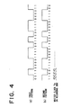
- the first and second pattern generators 17 and 18 produce first and second run-up patterns "00110000111100” and "11001111000011", which start from 0 and 1, respectively.
- the first and second run-up patterns are switched by the multiplexer 20 and outputted therefrom.
- the manner of switching between the first and second run-up patterns by the multiplexer 20, that is, whether a run-up period should be started from the first run-up pattern or the second run-up pattern, is determined by an end pattern of a code word supplied from the multiplexer 4.
- the multiplexer 20 controlled by an end pattern detected by and supplied from the end pattern detector 19 selects and outputs one of the first and second run-up patterns.
- a first run-up pattern stored in memories 101 to 114 is supplied to a parallel/serial converter 115.
- the parallel/serial converter 115 converts the first run-up pattern into a serial signal in the order from the LSB of the memory 101 to the MSB of the memory 114, and supplies the resultant serial signal to the multiplexer 20.
- a second run-up pattern stored in memories 117 to 130 is supplied to a parallel/serial converter 131.
- the parallel/serial converter 131 converts the second run-up pattern into a serial signal in the order from the LSB of the memory 117 to the MSB of the memory 130 and supplies the resultant serial signal to the multiplier 20.
- the multiplexer 20 should select the first run-up pattern or the second run-up pattern as a starting pattern for a run-up period, is determined by an end pattern of an immediately preceding code word supplied from the multiplexer 4 to an end pattern discriminator 133 of the end pattern detector 19.
- the BIT 12 of the end pattern of the immediately preceding code word is 1, as shown at A in Fig.
- the first run-up pattern outputted from the first pattern generator 17 is selected in the multiplexer 20 by a judgement signal supplied from a judgement signal generator 134 at the timing shown at D in Fig. 3 so that a run-up pattern is outputted from the run-up code generator 3 to provide a first run-up pattern shown at (a) in Fig. 4.
- the second run-up pattern outputted from the second pattern generator 18 is selected so that a run-up pattern is outputted from the run-up code generator 3 to provide a second run-up pattern shown at (b) in Fig. 4.
- the run-up pattern, sync pattern and code word thus produced are converted into a time-series serial signal by the multiplexer 4 in accordance with the recording format.
- the time-series serial signal is supplied to the code converter 1, the sync generator 2 and the run-up code generator 3 and is also supplied through the recording amplifier 5 to the recording head 6 so that it is recorded on the recording medium 7 by the recording head 6.
- the signal recorded on the recording medium 7 is reproduced by the reproducing head 8, is passed through the reproducing amplifier 9, and is supplied to the equalizer 11 after the compensation for the differentiating characteristic of the electro-magnetic and magnetio-electric conversion mechanisms has been made by the integrator 10.
- the equalizer 11 optimum equalization is made through a control by the automatic equalization controller 12 to make compensation for an inter-code interference of the reproduced signal which may be caused by an influence of the electro-magnetic and magneto-electric conversion mechanisms including the recording head 6, the recording medium 7 and the reproducing head 8.
- each of the reproduced signal X equalized by the equalizer 11 and band-limited by the low pass filter 13 and the reproduced data Y obtained by supplying the reproduced signal X to the zero-crossing detector 14 is divided into two (high and low) frequency regions as shown in Fig. 5, the signal energy level of the reproduced signal X and the reproduced data Y in each frequency region are compared with each other to obtain an errer signal, and an equalization amount is determined on the basis of the error signal so that the equalization characteristic becomes optimum.
- the equalizer 11 is controlled in accordance with the determined equalization amount.
- the reproduced signal subjected to the optimum equalization is digitized by the zero-crossing detector 14 into binary reproduced data and thereafter it is supplied to the discriminator 15 and the clock reproducing PLL 16.
- the clock reproducing PLL 16 reproduces a clock sinal synchronized with the rising and falling edges of the reproduced data supplied from the zero-crossing detector 14.
- the discriminator 15 the reproduced data supplied from the zero-crossing detector 14 is discriminated at a period of the clock signal reproduced by the clock reproduing PLL 16.
- the data output from the discriminator 15 and the reproduced clock output from the clock reproducing PLL 16 are supplied to the succeeding decoding circuit (not shown).
- the run-up code generator 3 is provided to produce a run-up pattern satisfying the condition for the short-time settlement of the clock reproducing PLL 16 and the automatic equalization controller 12, and the run-up pattern produced by the run-up code generator 3 is recorded in a run-up period during recording.
- the signal spectra of the run-up pattern reproduced in the run-up period exist at f m /28, f m ⁇ 3/28, f m ⁇ 5/28, f m /4 and f m ⁇ 9/28, in a signal pass band on the reproducing side, and the signal energy is distributed balancedly in each of the low and high frequency regions for signal comparison.
- the circuit operation of the automatic equalization controller 12 can be settled stably by using the reproduced signal in the run-up period. Accordingly, it is possible to make accurate code detection in the sync period and in the data period in which reproduction is performed continuously after the signal reproduction in the run-up period. Further, since the equalizer can be settled into an optimum equalization condition by the signal reproduction in the run-up period, even if reproduction is made of portions where the recording state has changed stepwise at the time of edition, etc., erroneous discrimination of codes in the sync period and in the data period can be suppressed to a minimum, thereby providing a great practical effect.
- the run-up patterns to be produced by the run-up code generator may be "01100001111001" and "10011110000110", for example, which are obtained by making a bit-shift of the run-up patterns shown in Fig. 4.
- the run-up pattern produced by the run-up code generator 3 includes a first run-up pattern "00111001100011” produced by the first pattern generator 17 and a second run-up pattern "11000110011100” produced by the second pattern generator 18 (this is the case where a combination of consecutive bit numbers 2 and 3 is used).
- either one of the run-up patterns is always selected in accordance with an end pattern of an immediately preceding code word supplied from the multiplexer 4.
- the selected run-up pattern is outputted repetitively, and it is recorded during the run-up period.
- the signal spectra at the time of reproducing the run-up period are distributed at f m /14, f m ⁇ 3/14 and f m ⁇ 5/14 in a signal pass band on the reproducing side, and, as a result, signal energy is distributed at lower and higher signal comparison regions, respectively, of the automatic equalization controller 12. Accordingly, it is possible to obtain the same advantage as described before.
- an example of the run-up pattern produced by the run-up code generator 3 in this case may be "01001101" (the case where a combination of consecutive bit numbers 1 and 2 is used), or "01110001" (the case where a combination of consecutive bit numbers 1 and 3 is used).
Landscapes
- Engineering & Computer Science (AREA)
- Signal Processing (AREA)
- Signal Processing For Digital Recording And Reproducing (AREA)
Applications Claiming Priority (2)
| Application Number | Priority Date | Filing Date | Title |
|---|---|---|---|
| JP2073805A JP2746721B2 (ja) | 1990-03-23 | 1990-03-23 | ディジタル信号記録再生装置 |
| JP73805/90 | 1990-03-23 |
Publications (3)
| Publication Number | Publication Date |
|---|---|
| EP0448370A2 true EP0448370A2 (de) | 1991-09-25 |
| EP0448370A3 EP0448370A3 (en) | 1991-12-18 |
| EP0448370B1 EP0448370B1 (de) | 1995-05-24 |
Family
ID=13528752
Family Applications (1)
| Application Number | Title | Priority Date | Filing Date |
|---|---|---|---|
| EP91302402A Expired - Lifetime EP0448370B1 (de) | 1990-03-23 | 1991-03-20 | System zur Aufzeichnung/Wiedergabe digitaler Signale |
Country Status (5)
| Country | Link |
|---|---|
| US (1) | US5267099A (de) |
| EP (1) | EP0448370B1 (de) |
| JP (1) | JP2746721B2 (de) |
| CN (1) | CN1023285C (de) |
| DE (1) | DE69109906T2 (de) |
Cited By (1)
| Publication number | Priority date | Publication date | Assignee | Title |
|---|---|---|---|---|
| WO1993014500A1 (en) * | 1992-01-07 | 1993-07-22 | Samsung Electronics Co., Ltd. | Video tape format for providing special effects capabilities |
Families Citing this family (5)
| Publication number | Priority date | Publication date | Assignee | Title |
|---|---|---|---|---|
| JPH06150216A (ja) * | 1992-11-02 | 1994-05-31 | Sony Corp | ディジタル信号再生方法とその装置 |
| EP0615236B1 (de) * | 1993-03-08 | 1999-11-24 | Matsushita Electric Industrial Co., Ltd. | Datenaufzeichnungsmethode |
| US6084907A (en) * | 1996-12-09 | 2000-07-04 | Matsushita Electric Industrial Co., Ltd. | Adaptive auto equalizer |
| IL147610A0 (en) * | 2000-05-16 | 2002-08-14 | Koninkl Philips Electronics Nv | Information carrier and devices for scanning the information carrier |
| CN100490541C (zh) * | 2005-09-07 | 2009-05-20 | 宏芯科技股份有限公司 | 降低视讯应用中锁相回路晃动的方法 |
Family Cites Families (8)
| Publication number | Priority date | Publication date | Assignee | Title |
|---|---|---|---|---|
| JPS5677912A (en) * | 1979-11-28 | 1981-06-26 | Sony Corp | Digital recorder for video signal |
| US4604655A (en) * | 1982-10-23 | 1986-08-05 | Pioneer Electronic Corporation | Method of recording and reproducing video format signal |
| US4580176A (en) * | 1983-11-21 | 1986-04-01 | International Business Machines Corporation | Adaptive equalization circuit for magnetic recording channels utilizing signal timing |
| DE3427879A1 (de) * | 1984-07-28 | 1986-01-30 | Robert Bosch Gmbh, 7000 Stuttgart | Aufzeichnungsverfahren fuer digital codierte signale, insbesondere fuer zeitkomprimierte digital codierte tonsignale |
| DE3682412D1 (de) * | 1985-02-25 | 1991-12-19 | Matsushita Electric Industrial Co Ltd | Digitales datenaufzeichnungs- und -wiedergabeverfahren. |
| JP2592054B2 (ja) * | 1986-01-31 | 1997-03-19 | シャープ株式会社 | データ記録方法 |
| US4991034A (en) * | 1987-12-11 | 1991-02-05 | Sanyo Electric Co., Ltd. | DC restoration circuit for restoring and compensating a low frequency component lost in a digital signal |
| JP2629255B2 (ja) * | 1988-03-31 | 1997-07-09 | 松下電器産業株式会社 | 自動等化回路 |
-
1990
- 1990-03-23 JP JP2073805A patent/JP2746721B2/ja not_active Expired - Lifetime
-
1991
- 1991-03-18 US US07/670,418 patent/US5267099A/en not_active Expired - Lifetime
- 1991-03-20 DE DE69109906T patent/DE69109906T2/de not_active Expired - Lifetime
- 1991-03-20 EP EP91302402A patent/EP0448370B1/de not_active Expired - Lifetime
- 1991-03-23 CN CN91101804.2A patent/CN1023285C/zh not_active Expired - Lifetime
Cited By (1)
| Publication number | Priority date | Publication date | Assignee | Title |
|---|---|---|---|---|
| WO1993014500A1 (en) * | 1992-01-07 | 1993-07-22 | Samsung Electronics Co., Ltd. | Video tape format for providing special effects capabilities |
Also Published As
| Publication number | Publication date |
|---|---|
| CN1056390A (zh) | 1991-11-20 |
| EP0448370B1 (de) | 1995-05-24 |
| CN1023285C (zh) | 1993-12-22 |
| DE69109906D1 (de) | 1995-06-29 |
| JPH03273574A (ja) | 1991-12-04 |
| EP0448370A3 (en) | 1991-12-18 |
| US5267099A (en) | 1993-11-30 |
| DE69109906T2 (de) | 1996-02-22 |
| JP2746721B2 (ja) | 1998-05-06 |
Similar Documents
| Publication | Publication Date | Title |
|---|---|---|
| US5136436A (en) | Apparatus for recording a digital information signal and utilizing the digital sum value thereof to record an auxiliary digital signal, and apparatus for reproducing such recorded signals | |
| EP0492704B1 (de) | Anordnung zum Aufzeichnen von Takteinlauf-Codewörtern in einer Spur auf einem magnetischen Aufzeichnungsträger | |
| EP0472375B1 (de) | Datenumsetzungsverfahren und Verfahren zur Bildung von Pilotsignalen mit diesem Verfahren | |
| US5068752A (en) | Apparatus for recording/reproducing a digital audio signal with a video signal | |
| US6633443B1 (en) | Peak shift correction circuit and magnetic storage medium playback apparatus | |
| US5270876A (en) | Apparatus for reproducing data recorded on a magnetic recording medium | |
| EP0448370B1 (de) | System zur Aufzeichnung/Wiedergabe digitaler Signale | |
| EP0310356B1 (de) | Datenwiedergabegerät | |
| EP0526217A2 (de) | Verfahren und Vorrichtung zum Aufzeichnen und Wiedergeben von digitalen Audio-Signalen | |
| US4984099A (en) | Apparatus for decoding a transmitted signal | |
| EP0309150B1 (de) | Datenwiedergabegerät | |
| EP0650263A1 (de) | Verfahren zur Kodierung und Dekodierung und magnetischer Aufnahmeapparat | |
| US6785212B1 (en) | Optical disk reproducing apparatus having a viterbi detector | |
| US5673046A (en) | Analog-to-digital conversion circuit for use in information reproduction apparatuses | |
| JP2000182335A (ja) | Pll回路及びそれを備えた光ディスク装置 | |
| US5170296A (en) | Apparatus for reproducing magnetically recorded signals with amplitude correction | |
| JP3006565B2 (ja) | ディジタル信号記録装置 | |
| EP0700045A2 (de) | Referenztaktgeneratorschaltung | |
| US6633527B1 (en) | High-density disk recording medium and apparatus and method of reproducing data recorded therein | |
| US6671455B1 (en) | Magnetic recording apparatus and method therefor, and magnetic recording and reproduction apparatus and method therefor | |
| JP3311428B2 (ja) | トラック追従制御方法 | |
| JPH1055627A (ja) | 同期回路 | |
| JP2637644B2 (ja) | 情報変換方法及びパイロット信号生成方法及び回転磁気ヘッド装置 | |
| Tsuji et al. | Digital Audio Recording in M II Format VTR | |
| JPH0982034A (ja) | ビットスリップのキャンセル方法及びキャンセル回路 |
Legal Events
| Date | Code | Title | Description |
|---|---|---|---|
| PUAI | Public reference made under article 153(3) epc to a published international application that has entered the european phase |
Free format text: ORIGINAL CODE: 0009012 |
|
| AK | Designated contracting states |
Kind code of ref document: A2 Designated state(s): DE FR GB |
|
| PUAL | Search report despatched |
Free format text: ORIGINAL CODE: 0009013 |
|
| AK | Designated contracting states |
Kind code of ref document: A3 Designated state(s): DE FR GB |
|
| RIN1 | Information on inventor provided before grant (corrected) |
Inventor name: MINAGUCHI, HOTAKA Inventor name: KAWAKAMI, YASUNORI Inventor name: FUJIWARA, MIKIO Inventor name: UEHARA, TOSHIHIRO Inventor name: TOGASHI, SHIGEKAZU |
|
| RHK1 | Main classification (correction) |
Ipc: H04N 5/91 |
|
| RIN1 | Information on inventor provided before grant (corrected) |
Inventor name: MINAGUCHI, HOTAKA Inventor name: UEHARA, TOSHIHIRO Inventor name: KAWAKAMI, YASUNORI Inventor name: FUJIWARA, MIKIO Inventor name: TOGASHI, SIGEKAZU |
|
| 17P | Request for examination filed |
Effective date: 19920218 |
|
| 17Q | First examination report despatched |
Effective date: 19931129 |
|
| GRAA | (expected) grant |
Free format text: ORIGINAL CODE: 0009210 |
|
| AK | Designated contracting states |
Kind code of ref document: B1 Designated state(s): DE FR GB |
|
| REF | Corresponds to: |
Ref document number: 69109906 Country of ref document: DE Date of ref document: 19950629 |
|
| ET | Fr: translation filed | ||
| PLBE | No opposition filed within time limit |
Free format text: ORIGINAL CODE: 0009261 |
|
| STAA | Information on the status of an ep patent application or granted ep patent |
Free format text: STATUS: NO OPPOSITION FILED WITHIN TIME LIMIT |
|
| 26N | No opposition filed | ||
| REG | Reference to a national code |
Ref country code: GB Ref legal event code: IF02 |
|
| REG | Reference to a national code |
Ref country code: GB Ref legal event code: 732E Free format text: REGISTERED BETWEEN 20091105 AND 20091111 |
|
| REG | Reference to a national code |
Ref country code: FR Ref legal event code: TP |
|
| PGFP | Annual fee paid to national office [announced via postgrant information from national office to epo] |
Ref country code: FR Payment date: 20100324 Year of fee payment: 20 |
|
| PGFP | Annual fee paid to national office [announced via postgrant information from national office to epo] |
Ref country code: GB Payment date: 20100317 Year of fee payment: 20 |
|
| PGFP | Annual fee paid to national office [announced via postgrant information from national office to epo] |
Ref country code: DE Payment date: 20100422 Year of fee payment: 20 |
|
| REG | Reference to a national code |
Ref country code: DE Ref legal event code: R071 Ref document number: 69109906 Country of ref document: DE |
|
| REG | Reference to a national code |
Ref country code: GB Ref legal event code: PE20 Expiry date: 20110319 |
|
| PG25 | Lapsed in a contracting state [announced via postgrant information from national office to epo] |
Ref country code: GB Free format text: LAPSE BECAUSE OF EXPIRATION OF PROTECTION Effective date: 20110319 |
|
| PG25 | Lapsed in a contracting state [announced via postgrant information from national office to epo] |
Ref country code: DE Free format text: LAPSE BECAUSE OF EXPIRATION OF PROTECTION Effective date: 20110320 |