EP0448396A2 - Elektrischer Verbinder für flüssigkeitsdichte Röhre - Google Patents
Elektrischer Verbinder für flüssigkeitsdichte Röhre Download PDFInfo
- Publication number
- EP0448396A2 EP0448396A2 EP91302480A EP91302480A EP0448396A2 EP 0448396 A2 EP0448396 A2 EP 0448396A2 EP 91302480 A EP91302480 A EP 91302480A EP 91302480 A EP91302480 A EP 91302480A EP 0448396 A2 EP0448396 A2 EP 0448396A2
- Authority
- EP
- European Patent Office
- Prior art keywords
- conduit
- friction
- gland nut
- electrical connector
- liquidtight
- Prior art date
- Legal status (The legal status is an assumption and is not a legal conclusion. Google has not performed a legal analysis and makes no representation as to the accuracy of the status listed.)
- Granted
Links
- 210000004907 gland Anatomy 0.000 claims abstract description 42
- 238000010276 construction Methods 0.000 claims abstract description 7
- 239000000463 material Substances 0.000 claims description 4
- 239000004033 plastic Substances 0.000 abstract description 11
- 238000003780 insertion Methods 0.000 abstract description 3
- 230000037431 insertion Effects 0.000 abstract description 3
- 230000002708 enhancing effect Effects 0.000 abstract 1
- 239000002184 metal Substances 0.000 description 5
- 239000004677 Nylon Substances 0.000 description 2
- 238000009434 installation Methods 0.000 description 2
- 229920001778 nylon Polymers 0.000 description 2
- 239000002131 composite material Substances 0.000 description 1
- 230000006835 compression Effects 0.000 description 1
- 238000007906 compression Methods 0.000 description 1
- 238000009413 insulation Methods 0.000 description 1
- 239000007788 liquid Substances 0.000 description 1
- 238000000034 method Methods 0.000 description 1
- 239000000126 substance Substances 0.000 description 1
Images
Classifications
-
- H—ELECTRICITY
- H02—GENERATION; CONVERSION OR DISTRIBUTION OF ELECTRIC POWER
- H02G—INSTALLATION OF ELECTRIC CABLES OR LINES, OR OF COMBINED OPTICAL AND ELECTRIC CABLES OR LINES
- H02G3/00—Installations of electric cables or lines or protective tubing therefor in or on buildings, equivalent structures or vehicles
- H02G3/02—Details
- H02G3/06—Joints for connecting lengths of protective tubing or channels, to each other or to casings, e.g. to distribution boxes; Ensuring electrical continuity in the joint
- H02G3/0616—Joints for connecting tubing to casing
- H02G3/0691—Fixing tubing to casing by auxiliary means co-operating with indentations of the tubing, e.g. with tubing-convolutions
Definitions
- the present invention relates to electrical connectors, and more particularly to liquidtight connectors which connect electrical components, such as junction boxes or outlet boxes with liquidtight flexible conduits.
- Liquidtight flexible conduit is used in many applications, including industrial applications, to protect electric current-carrying wires.
- the wires which may be bare or covered by insulation, are pulled through the conduit which is typically tubular and has an axial bore.
- the wires contained in such conduit may be protected from the environments in various applications.
- the conduit may be smooth or convoluted.
- Connectors of this type may be formed of metal, plastic or both metal and plastic.
- U.S. Patent 4,842,548 issued to Bolante on June 27, 1989 shows an all-plastic connector
- U.S. Patent 3,659,880 issued to Goldsobel on May 2, 1972 shows a connector with portions made of plastic and metal.
- various other known connector constructions have been developed.
- connectors having flexible fingers, conduit engagement portions with screw threads for attachment to conduit, gripping serrations or teeth and deformable wedges are all known.
- ease of installation is also desirable. Accordingly, for use particularly in the field, a more efficient use of tightening techniques wherein easy tightening can be effected by either hand or tools is advantageous.
- an electrical connector for connecting liquidtight electrical conduit to an electrical component, comprising: a body including a component connecting portion, a flange portion and a conduit connecting portion and a bore extending axially therethrough, said component connecting portion projecting axially from said flange portion in one direction and comprising external thread means for connecting said body to said electrical component, said conduit connecting portion projecting axially from said flange portion in a direction opposite said component connecting portion, said conduit connecting portion including an elongate internal tubular ferrule through which said body bore extends and an outer cylindrical ring, said ferrule and said ring being radially spaced and defining a cavity therebetween, said ferrule including a conduit supporting surface defining one wall of said cavity, said conduit supporting surface including a surface portion tapering outwardly toward said ring in the direction toward said flange portion, said tapering surface portion having thereon friction-reducing means for engageably receiving an interior surface of a liquidtight conduit, said ring including external threads and
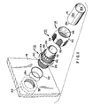
- Figure 1 is a perspective, exploded view of a preferred embodiment of the connector of the subject invention showing a portion of a flexible liquidtight conduit and a panel of an electrical component to which the connector is to be connected.
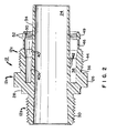
- Figure 2 is a longitudinal cross-section of the body of the electrical connector of Figure 1.
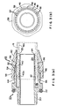
- Figure 3(a) is a longitudinal cross-sectional view of the connector of Figure 1 showing the body and gland nut of the subject connector in a pre-connected condition to a flexible conduit.
- Figure 3(b) is a plan view in schematic form of the connector in the pre-connected condition of Figure 3(a).
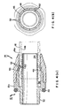
- Figure 4(a) is a longitudinal cross-section of the connector of Figure 1 shown in connected condition to a flexible conduit.
- Figure 4(b) is a plan view, in schematic form, of the electrical connector of 4(a) in connected condition.
- the connector 10 is a two-part, all-plastic connector comprising a body 12 and a gland nut 14.
- the connector 10 as will be described more fully hereinbelow, is particularly adapted to connect in liquidtight manner to a flexible, liquidtight conduit 16 which may have a smooth exterior surface 16a, as shown, or a convoluted surface.
- the conduit interior surface 16b is smooth.
- the connector body 12 is particularly adapted for liquidtight connection to a panel of an electrical component, such as an electrical outlet or junction box by means of a lock nut 20 and an elastomeric O-ring 22 which is resiliently compressed between the body 12 and the panel 18.
- the connector body 12 is preferably formed of one-piece construction of insulative material, preferably plastic, such as nylon.
- the body 12 is of generally hollow cylindrical construction comprising a centrally located flange portion 12a a component connecting portion 12b projecting from the flange portion 12a in one direction and a conduit connecting portion 12c projecting from the flange portion 12a in the opposite direction.
- An axial bore 24 extends fully through the body 12.
- the flange portion 12a extends generally transversely to the axially extending bore 24 and, as shown in Figure 1, comprises a plurality of flat surfaces 26, preferably in hexagonal configuration, to facilitate tightening to the panel 18 by a suitable tool or by hand.
- the flange portion 12a further includes a cradle 28 preferably having a concave surface for seating the elastomeric O-ring 22 thereon for providing a liquidtight seal between the body 12 and the panel 18 of the electrical component to which the connector 10 is attached.
- the component connecting portion 12b includes a series of external threads 30 for mateable threadable engagement with the threads 32 of the lock nut 20, whereby the body 12 may be sealably secured to the electrical component panel 18.
- the threads 30 on the component connecting portion 12b of the body 12 are of diameter to fit through an opening 18a formed in the panel while the O-ring is compressed against the exterior surface of the panel 18 upon tightening the body 12 to the lock nut 20.
- interior threads may be provided on the inner surface of the opening 18a for engageable receipt of the threads 30 on the body connecting portion 12b.
- the conduit connecting portion 12c includes a longitudinally extending, elongate, internal tubular ferrule 34 through which the axially extending bore 24 extends. Radially spaced from the tubular ferrule 34 is an outer cylindrical ring 36. The ferrule 34 and the ring 36 define a generally tubular cavity 38 therebetween, for receipt of the flexible conduit 16, as will be described in detail hereinafter.
- the ferrule 34 includes an exterior surface 40 defining one wall of the cavity 38 for receiving and supporting thereon the interior surface 16b of the flexible conduit 16. As the ferrule exterior surface 40 extends into the cavity 38 toward the flange portion 12a, the outer diameter of the ferrule 34 increases, thereby providing a tapered surface 40a. Tapered surface 40a increases gradually outwardly toward the ring 36 in the direction deeper in the cavity 38 toward the flange portion 12a. In accordance with one aspect of the invention, on tapered surface 40a, there are provided a plurality of friction-reducing elements 42 thereon. In the preferred form of the invention, friction reducing elements 42 extend annularly around the tapered surface 40a and are longitudinally spaced and substantially parallel to each other.
- the tapered surface is provided with a plurality of recesses formed into the tapered surface 40a and circumferentially therearound.
- the outer surface portions of the surface 40a extending between the recesses define the friction reducing elements 42.
- the friction reducing elements may be defined by other structures, such as protrusions projecting outwardly from surface 40a and that the number of such friction reducing elements may vary in accordance with the preferred use.
- the body ring 36 comprises external threads 44 at a location proximate the flange portion 12a. Disposed more distally from the flange portion 12a and projecting longitudinally outward from the threads 44 on ring 36 are a plurality of cantilevered, flexible fingers 46. As illustrated in Figure 1, each finger 46 is separated from another finger 46 by a longitudinally extending slot 48. Each finger 46 terminates at its free distal end in a beveled outer surface 49. Disposed on the interior surface at the distal end of each finger 46 are relatively sharp teeth 50 or serrations for engagement with the outer surface 16a of conduit 16, as will be described. It should be appreciated that the number and shape of teeth 50 may vary.
- each finger 46 Projecting outwardly from the beveled outer surface of each finger 46 are a pair of friction-reducing members 52.
- the friction-reducing members 52 are defined by ridges which extend arcuately along the beveled surface 48 of each finger 46.
- the ridges 52 are substantially parallel to each other and are longitudinally spaced from each other on the beveled surface 49. Except for the spaces defined by the slots 48 between the fingers 46, the ridges 52 together extend substantially around the entire circumference of the body ring 36.
- Each ridge 52 comprises a generally curved surface having an apex which defines a point-contact for tangential engagement with the gland nut as will be described, in a manner to provide minimal bearing surface engagement with the gland nut upon tightening.
- an application of maximum force with minimum friction may be transmitted to the flexible fingers 46 upon tightening of the gland nut 14.
- the gland nut 14 is preferably formed in a unitary manner of insulative material, preferably plastic, such as nylon. Gland nut 14 has a central, axially extending bore 53 extending therethrough, for receipt of the conduit 16. Internal threads 54 are provided for mateable, threadable engagement with the ring external threads 44. On the interior of the gland nut 14 there is provided an inclined contact surface 56 of generally frusto-conical configuration and extending circumferentially around the interior surface of the gland nut 14.
- the exterior surface of the gland nut 14 comprises a portion having a series of flat surfaces 58 and a generally smooth, frusto-conical outer surface 60.
- a plurality of longitudinally extending grooves 62 that provide gripping surfaces for facilitating handling of the gland nut and hand tightening to the connector body 12.
- the connector body 12 is attached to the panel 18 of an electrical component by means of threadably attaching the lock nut 20 to the external threads 30 on the body 12 which extend through the panel opening 18a.
- the O-ring 22 is compressed against the outer surface of the panel 18, thereby providing a suitable liquidtight seal.
- the gland nut 14 is inserted over an electrical conduit 16 with the outer surface 16a of the conduit being received through the centrally located bore 53 of the gland nut 14.
- the electrical wires (not shown) contained interiorly of a conduit 16 are pulled through the central bore 24 of the body 12 for subsequent electrical connection inside the electrical component.
- the interior surface 16b of the conduit 16 is slid onto the conduit supporting surface 40 of the body ferrule 34.
- the conduit is hand pushed onto the ferrule such that the conduit extends into the cavity 38.
- the interior conduit surface 16b upon continued pushing, engages the tapered ferrule surface 40a and the friction-reducing elements 42 thereon.
- the conduit even though being radially stretched due to the movement along the outwardly tapering surface 40a, may be more readily hand inserted deeper into the cavity 38.
- a suitable liquidtight seal between the inner conduit surface 16b and the body ferrule 34 may be achieved by hand insertion.
- the end surface 16c of the conduit is cut unevenly by a user in the field, this deeper insertion into the cavity 38 will allow more tolerance in establishing the desired liquidtight seal.
- the gland nut 14 inner threads 54 are then threadably engaged with the ring external threads 44 as illustrated in Figure 3(a). Initial engagement is established between the inclined interior surface 56 on the gland nut 14 and the friction-reducing ridges 52. As illustrated in Figure 4(b), continued threadable tightening of the gland nut 14 on the body 12 causes the flexible fingers 46 to compress radially into engagement with the outer surface 16a of the conduit, thereby forcing the teeth 50 into gripping engagement with the conduit 16. During tightening of the gland nut 14 on the body 12, inasmuch as the gland nut surface 56 engages the ridges 52 in tangential contact, greater hand tightening of the gland nut may be effected to achieve the desired connection.
- friction-reducing ridges 52 extend arcuately along the outer surface of each of the fingers 46
- other friction-reducing members may be formed by either protrusions or recesses.
- friction-reducing members are preferably included on each of the flexible fingers 46, it should be noted that, while full reduced friction may not be achieved as in the preferred embodiment, friction-reducing members may be included on only some of the fingers 46.
- the body and gland nut described herein may be formed differently and be made of different materials than as described in the preferred embodiment.
- the body need not necessarily be of integral, one piece construction, but may be a composite of both metal and plastic.
- the gland nut may be made of metal. Accordingly, it should be understood that the preferred embodiment described herein is intended only in an illustrative rather than a limiting sense. The true scope of the invention is set forth in the claims appended hereto.
Landscapes
- Engineering & Computer Science (AREA)
- Architecture (AREA)
- Civil Engineering (AREA)
- Structural Engineering (AREA)
- Joints With Pressure Members (AREA)
- Connector Housings Or Holding Contact Members (AREA)
Applications Claiming Priority (2)
| Application Number | Priority Date | Filing Date | Title |
|---|---|---|---|
| US07/498,293 US5072072A (en) | 1990-03-23 | 1990-03-23 | Electrical connector for liquidtight conduit |
| US498293 | 1990-03-23 |
Publications (3)
| Publication Number | Publication Date |
|---|---|
| EP0448396A2 true EP0448396A2 (de) | 1991-09-25 |
| EP0448396A3 EP0448396A3 (en) | 1992-11-19 |
| EP0448396B1 EP0448396B1 (de) | 1995-07-12 |
Family
ID=23980432
Family Applications (1)
| Application Number | Title | Priority Date | Filing Date |
|---|---|---|---|
| EP91302480A Expired - Lifetime EP0448396B1 (de) | 1990-03-23 | 1991-03-21 | Elektrischer Verbinder für flüssigkeitsdichte Röhre |
Country Status (5)
| Country | Link |
|---|---|
| US (1) | US5072072A (de) |
| EP (1) | EP0448396B1 (de) |
| JP (1) | JP2836985B2 (de) |
| CA (1) | CA2038448C (de) |
| DE (1) | DE69111103T2 (de) |
Cited By (2)
| Publication number | Priority date | Publication date | Assignee | Title |
|---|---|---|---|---|
| DE20008148U1 (de) * | 2000-05-05 | 2001-09-06 | Reiku GmbH, 51674 Wiehl | Armatur zum Befestigen eines Wellrohres in einer Wandöffnung |
| EP2264848A1 (de) * | 2009-06-16 | 2010-12-22 | ebm-papst Mulfingen GmbH & Co. KG | Kabelverschraubung |
Families Citing this family (69)
| Publication number | Priority date | Publication date | Assignee | Title |
|---|---|---|---|---|
| US5295851A (en) * | 1992-10-02 | 1994-03-22 | Thomas & Betts Corporation | Electrical connector hub having improved sealing ring |
| BR7400587U (pt) * | 1994-03-24 | 1994-10-04 | Seabra Helio Lanfranchi | Aperfeiçoamento introduzido no processo de fabricação de luva de conexão para tubos |
| DE19503722A1 (de) * | 1995-02-04 | 1996-08-08 | Gardena Kress & Kastner Gmbh | Schlauchanschluß, insbesondere zum Anschluß von Schläuchen, wie Gartenschläuchen |
| US5702131A (en) * | 1996-03-01 | 1997-12-30 | Wagner Spray Tech Corporation | Outlet fitting for a portable turbine |
| US5872335A (en) * | 1997-06-30 | 1999-02-16 | Heyco Products, Inc. | 90 degree sealing nut |
| CN1251693A (zh) * | 1997-02-13 | 2000-04-26 | 海科产品公司 | 90度角密封螺帽 |
| US6300569B1 (en) | 1997-02-13 | 2001-10-09 | Heyco Products, Inc. | 90° sealing nut |
| US5915736A (en) * | 1997-07-18 | 1999-06-29 | Thomas & Betts International, Inc. | Integrally formed whip assembly for electrically interconnecting electrical appliances to a power source |
| AU690510B3 (en) * | 1997-09-16 | 1998-04-23 | Teh-Tsung Chiu | Device for fastening a cable to a board |
| US6849803B1 (en) * | 1998-01-15 | 2005-02-01 | Arlington Industries, Inc. | Electrical connector |
| US6682355B1 (en) * | 1998-01-15 | 2004-01-27 | Arlington Industries, Inc. | Electrical fitting for easy snap engagement of cables |
| US6043432A (en) * | 1998-01-15 | 2000-03-28 | Arlington Industries, Inc. | Snap in cable connector |
| US6100470A (en) * | 1999-02-26 | 2000-08-08 | Arlington Industries, Inc. | Separatable snap in connectors for pre-connectorized cable |
| FR2812134B1 (fr) * | 2000-07-21 | 2002-12-13 | Marechal Sepm | Dispositif de retenue axiale d'un element cylindrique et plus particulierement un cable |
| US6641177B1 (en) | 2000-08-25 | 2003-11-04 | Precision Design Concepts, Llc | Quick connect tube coupling and method of assembling the same |
| US6737584B2 (en) * | 2001-05-01 | 2004-05-18 | Bridgeport Fittings, Inc. | Electrical cable connector |
| US6444907B1 (en) * | 2001-05-01 | 2002-09-03 | Bridgeport Fittings, Inc. | Electrical cable connector |
| US6835088B2 (en) | 2001-06-20 | 2004-12-28 | Cooper Industries, Inc. | EMT rain-tight compression fittings |
| US6840483B1 (en) * | 2001-07-02 | 2005-01-11 | Bellsouth Intellectual Property Corporation | Cable feed bushing and method of installing a cable through a wall or other structure |
| US6616194B1 (en) * | 2001-10-22 | 2003-09-09 | Arlington Industries, Inc. | Liquid tight connector |
| US6642451B1 (en) * | 2001-10-22 | 2003-11-04 | Arlington Industries, Inc. | Electrical connector |
| KR100445807B1 (ko) * | 2002-02-06 | 2004-08-25 | 삼성광주전자 주식회사 | 업라이트형 진공청소기의 흡입 호스 조립체 |
| DE20211347U1 (de) * | 2002-07-27 | 2002-09-26 | Anton Hummel Verwaltungs Gmbh, 79183 Waldkirch | Anschlussarmatur |
| JP3947971B2 (ja) * | 2002-11-25 | 2007-07-25 | Smc株式会社 | 管継手 |
| US7014216B2 (en) * | 2003-04-29 | 2006-03-21 | Thc International, Llc | Joint assembly for flexible and semi-rigid pipings |
| DE102005005128B4 (de) * | 2005-02-04 | 2006-10-26 | Adc Gmbh | Dichtung für eine Abdeckung einer elektrischen Anschlussbuchse |
| US7429064B2 (en) * | 2005-05-04 | 2008-09-30 | Mm Plastic (Mfg.) Company, Inc. | Liquid tight fitting for conduit |
| US20080191102A1 (en) | 2005-11-09 | 2008-08-14 | Sioux Chief Mfg. Co., Inc. | Pipe hanger system with slidable pipe connection member |
| US7304251B1 (en) * | 2005-12-15 | 2007-12-04 | Arlington Industries, Inc. | Electrical fitting for snap in connection of cables |
| US7914048B2 (en) * | 2006-03-02 | 2011-03-29 | Sami Shemtov | Liquid-tight coupling device with screw-on ferrule device and method of use |
| US7431343B2 (en) * | 2007-03-06 | 2008-10-07 | Teh-Tsung Chiu | Joint structure for quickly connecting corrugated pipe |
| US20080272590A1 (en) * | 2007-05-02 | 2008-11-06 | Howard Joseph D | Reusable fitting, connector assembly and kit |
| KR100869758B1 (ko) * | 2007-05-16 | 2008-11-21 | 김명애 | 자동차 카메라의 케이블 방수방법 |
| US7735876B2 (en) * | 2008-01-03 | 2010-06-15 | Avc Industrial Corp. | Fastening device for cable and wave hose |
| MX2010013584A (es) | 2008-06-09 | 2011-04-05 | Prime Flexible Products Inc | Union de tubo flexible. |
| US20100084855A1 (en) * | 2008-10-07 | 2010-04-08 | Thomas & Betts International, Inc. | Economy liquidtight fitting |
| US8141831B2 (en) * | 2009-02-24 | 2012-03-27 | Sioux Chief Mfg. Co., Inc. | Hanger connector for flexible tubing |
| US8013250B2 (en) * | 2009-06-03 | 2011-09-06 | Tyco Electronics Corporation | Cable entry seal for passing a cable through a structure |
| US7955125B1 (en) | 2010-10-14 | 2011-06-07 | Souriau Usa, Inc. | Electrical connector with one end threadably connected to a junction box and other end configured to be connected to a mating electrical connector |
| FR2971642B1 (fr) * | 2011-02-16 | 2013-01-18 | Schneider Electric Ind Sas | Dispositif de commande ou de signalisation electrique |
| US20120299296A1 (en) * | 2011-05-24 | 2012-11-29 | Nordson Corporation | Compression Connector for Flexible Tubing |
| US8910980B2 (en) | 2011-11-08 | 2014-12-16 | Thomas & Betts International, Inc. | Liquid-tight fitting |
| US20130315665A1 (en) * | 2012-05-24 | 2013-11-28 | Fenner U.S., Inc. | Mounting device |
| US9490619B2 (en) | 2012-10-25 | 2016-11-08 | Bridgeport Fittings, Inc. | Push-on liquidtight conduit fitting |
| US9618051B2 (en) | 2012-12-06 | 2017-04-11 | Fenner U.S., Inc. | Method and apparatus for mounting a machine element onto a shaft |
| KR200473779Y1 (ko) | 2013-03-18 | 2014-07-31 | 주식회사 코뿔소 | 주름관용 조인트 장치 |
| US20140318856A1 (en) * | 2013-04-25 | 2014-10-30 | Timothy Carman | Seal Adapter Device and Kit Assembly |
| US9371948B2 (en) | 2013-08-14 | 2016-06-21 | Heyco, Inc. | Liquid-tight connector |
| CN104518376A (zh) * | 2013-09-30 | 2015-04-15 | 鸿富锦精密工业(深圳)有限公司 | 连接器及使用该连接器的电子设备 |
| US9601914B2 (en) | 2014-01-13 | 2017-03-21 | Avc Industrial Corp. | Cable and flexible conduit gland assembly |
| US9231397B2 (en) | 2014-01-13 | 2016-01-05 | Avc Industrial Corp. | Cable gland assembly |
| GB201405132D0 (en) * | 2014-03-21 | 2014-05-07 | Indian Ocean Medical Inc | Fixation apparatus |
| CN107429843B (zh) | 2014-03-28 | 2019-12-17 | 配件收购合并公司 | 液密式应变消除件 |
| TWM484660U (zh) * | 2014-05-16 | 2014-08-21 | Kenswell Tube Forming Inc | 液壓管接頭 |
| US10422454B2 (en) * | 2014-06-30 | 2019-09-24 | Eaton Intelligent Power Limited | Coupling with integral fluid penetration barrier |
| USD815516S1 (en) * | 2014-09-02 | 2018-04-17 | General Electric Company | Connector joint |
| US9831649B1 (en) | 2016-01-26 | 2017-11-28 | Arlington Industries, Inc. | Rain tight fitting for electrical metal tubing |
| US10654395B1 (en) | 2016-04-08 | 2020-05-19 | Trinity Bay Equipment Holdings, LLC | Pipe deployment trailer |
| MX378284B (es) | 2016-04-08 | 2025-03-10 | Flexsteel Pipeline Tech Inc | Remolque de despliegue de tuberia. |
| US11283252B2 (en) | 2016-04-25 | 2022-03-22 | Ez Electrical System Solutions, Llc | Wire protector system and method |
| US11362498B2 (en) | 2016-04-25 | 2022-06-14 | Glenn Liubakka | Apparatus for producing different sized boxes |
| US12021364B2 (en) | 2016-04-25 | 2024-06-25 | Glenn Liubakka | Method for mounting electrical boxes |
| US11165231B2 (en) * | 2016-04-25 | 2021-11-02 | Glenn Liubakka | Apparatus for different sized boxes |
| US10364847B2 (en) | 2016-07-20 | 2019-07-30 | Fenner U.S., Inc. | Mounting device |
| US10263361B1 (en) | 2016-12-23 | 2019-04-16 | Arlington Industries, Inc. | Transition fitting for photovoltaic installations |
| CN111902666B (zh) * | 2018-03-19 | 2022-06-14 | 富世华股份有限公司 | 具有夹紧螺帽的软管接头 |
| DE102019123671A1 (de) * | 2019-09-04 | 2021-03-04 | Pflitsch Gmbh & Co. Kg | Verschraubungssystem Verfahren zur Verschraubung armierter Langformteile sowie Verwendung eines Verschraubungssystems |
| US11788625B2 (en) | 2020-05-27 | 2023-10-17 | Hoffman Enclosures, Inc. | Hygienic hole seal |
| JP7737147B2 (ja) | 2022-03-07 | 2025-09-10 | サーパス工業株式会社 | 継手ユニットおよび継手ユニットの組立方法 |
Family Cites Families (21)
| Publication number | Priority date | Publication date | Assignee | Title |
|---|---|---|---|---|
| US2561827A (en) * | 1947-09-19 | 1951-07-24 | Gabriel Co | Hose coupling |
| US3184706A (en) * | 1962-09-27 | 1965-05-18 | Itt | Coaxial cable connector with internal crimping structure |
| US3243206A (en) * | 1963-12-30 | 1966-03-29 | Thomas & Betts Co Inc | Fitting for connecting pliable conduit to apertured member |
| US3394954A (en) * | 1966-05-06 | 1968-07-30 | Sarns Inc | Tube coupling for medical appliances |
| DE6927527U (de) * | 1967-07-31 | 1969-11-13 | Kupex Ag | Schlauchkupplung. |
| US3624591A (en) * | 1970-06-01 | 1971-11-30 | Harry P Buberniak | Electrical cable connector assembly |
| US3659880A (en) * | 1970-11-05 | 1972-05-02 | Norman Goldsobel | Connector for flexible conduit |
| US3749424A (en) * | 1972-06-05 | 1973-07-31 | Kdi American Products Inc | Water conduit connector |
| US3958818A (en) * | 1972-08-28 | 1976-05-25 | Litton Industrial Products, Inc. | Fitting assembly for flexible tubing |
| JPS5495899U (de) * | 1977-12-08 | 1979-07-06 | ||
| US4209661A (en) * | 1978-03-16 | 1980-06-24 | Indian Head Inc. | Conductor clamping device |
| US4225162A (en) * | 1978-09-20 | 1980-09-30 | Amp Incorporated | Liquid tight connector |
| US4293178A (en) * | 1979-08-03 | 1981-10-06 | Hop Lee | Coupling for an electric cable |
| DE2952468A1 (de) * | 1979-12-27 | 1981-07-16 | Armaturenfabrik Hermann Voss GmbH + Co, 5272 Wipperfürth | Steckbare verbindungsvorrichtung mit schnappverschluss |
| US4481697A (en) * | 1982-05-28 | 1984-11-13 | General Signal Corporation | Combined strain relief and cord grip |
| US4451069A (en) * | 1982-08-09 | 1984-05-29 | Smith Investment Company | Quick connect fluid coupling |
| US4679827A (en) * | 1984-12-28 | 1987-07-14 | Thomas & Betts Corporation | Raintight and oiltight connector for flexible conduit |
| JPH024303Y2 (de) * | 1986-03-19 | 1990-01-31 | ||
| US4842548A (en) * | 1987-04-13 | 1989-06-27 | Appleton Electric Co. | Plastic conduit connector for flexible conduit |
| JPH0314632Y2 (de) * | 1987-10-19 | 1991-04-02 | ||
| US4900068A (en) * | 1988-12-19 | 1990-02-13 | Heyco Molded Products, Inc. | Liquid tight connector for flexible non-metallic conduit and flexible non-metallic tubing |
-
1990
- 1990-03-23 US US07/498,293 patent/US5072072A/en not_active Expired - Lifetime
-
1991
- 1991-03-18 CA CA002038448A patent/CA2038448C/en not_active Expired - Lifetime
- 1991-03-21 DE DE69111103T patent/DE69111103T2/de not_active Expired - Lifetime
- 1991-03-21 EP EP91302480A patent/EP0448396B1/de not_active Expired - Lifetime
- 1991-03-25 JP JP3060456A patent/JP2836985B2/ja not_active Expired - Lifetime
Cited By (2)
| Publication number | Priority date | Publication date | Assignee | Title |
|---|---|---|---|---|
| DE20008148U1 (de) * | 2000-05-05 | 2001-09-06 | Reiku GmbH, 51674 Wiehl | Armatur zum Befestigen eines Wellrohres in einer Wandöffnung |
| EP2264848A1 (de) * | 2009-06-16 | 2010-12-22 | ebm-papst Mulfingen GmbH & Co. KG | Kabelverschraubung |
Also Published As
| Publication number | Publication date |
|---|---|
| CA2038448C (en) | 1994-04-19 |
| DE69111103D1 (de) | 1995-08-17 |
| US5072072A (en) | 1991-12-10 |
| DE69111103T2 (de) | 1995-11-23 |
| JPH04229011A (ja) | 1992-08-18 |
| EP0448396B1 (de) | 1995-07-12 |
| EP0448396A3 (en) | 1992-11-19 |
| JP2836985B2 (ja) | 1998-12-14 |
| CA2038448A1 (en) | 1991-09-24 |
Similar Documents
| Publication | Publication Date | Title |
|---|---|---|
| EP0448396B1 (de) | Elektrischer Verbinder für flüssigkeitsdichte Röhre | |
| US5051541A (en) | Plastic electrical connector for liquidtight conduit | |
| US5276280A (en) | Electrical cable connector | |
| US5200575A (en) | Connector assembly for conduit | |
| US4250348A (en) | Clamping device for cables and the like | |
| US5068496A (en) | Snap-in connector | |
| US5866853A (en) | Liquid-tight, strain-relief connector for connecting conduit and the like | |
| US4022966A (en) | Ground connector | |
| CA2949715C (en) | Grommet for a cable connector and a strain relief cable fitting having an insert | |
| EP1468477B1 (de) | Flexible verbindungs-kabelzugentlastungseinrichtung | |
| US6335488B1 (en) | Snap in cable connector | |
| US5543582A (en) | Liquid tight cord grip | |
| JPH08501863A (ja) | 樹脂管の外周面係合用継手 | |
| US4386817A (en) | Cable underpinning | |
| EP0798815A3 (de) | Verbinderanordnung für Koaxialkabel mit gewelltem Aussenleiter | |
| MXPA02002727A (es) | Dispositivo de retencion axial de un elemento cilindrico y mas particularmente un cable. | |
| EP0131076B1 (de) | Klemmhülse, Kupplung und Kupplungsverfahren | |
| AU726504B3 (en) | Method and apparatus for connecting an object to a device | |
| IE59005B1 (en) | Helving device for securing a handle to a tool | |
| US4355854A (en) | Self-locking means | |
| US3488073A (en) | Attaching device for convoluted tubing | |
| US5322451A (en) | Vibration resistant electrical coupling with tactile indication | |
| EP0200339A2 (de) | Rohrkupplungen | |
| EP1016166B1 (de) | Ein verbinder | |
| EP0631346B1 (de) | Elektrischer Verbinder |
Legal Events
| Date | Code | Title | Description |
|---|---|---|---|
| PUAI | Public reference made under article 153(3) epc to a published international application that has entered the european phase |
Free format text: ORIGINAL CODE: 0009012 |
|
| AK | Designated contracting states |
Kind code of ref document: A2 Designated state(s): BE CH DE ES FR GB IT LI LU NL SE |
|
| PUAL | Search report despatched |
Free format text: ORIGINAL CODE: 0009013 |
|
| AK | Designated contracting states |
Kind code of ref document: A3 Designated state(s): BE CH DE ES FR GB IT LI LU NL SE |
|
| 17P | Request for examination filed |
Effective date: 19930506 |
|
| 17Q | First examination report despatched |
Effective date: 19940217 |
|
| RAP3 | Party data changed (applicant data changed or rights of an application transferred) |
Owner name: THOMAS & BETTS CORPORATION |
|
| GRAA | (expected) grant |
Free format text: ORIGINAL CODE: 0009210 |
|
| AK | Designated contracting states |
Kind code of ref document: B1 Designated state(s): BE CH DE ES FR GB IT LI LU NL SE |
|
| PG25 | Lapsed in a contracting state [announced via postgrant information from national office to epo] |
Ref country code: IT Free format text: LAPSE BECAUSE OF FAILURE TO SUBMIT A TRANSLATION OF THE DESCRIPTION OR TO PAY THE FEE WITHIN THE PRE;WARNING: LAPSES OF ITALIAN PATENTS WITH EFFECTIVE DATE BEFORE 2007 MAY HAVE OCCURRED AT ANY TIME BEFORE 2007. THE CORRECT EFFECTIVE DATE MAY BE DIFFERENT FROM THE ONE RECORDED.SCRIBED TIME-LIMIT Effective date: 19950712 Ref country code: NL Free format text: LAPSE BECAUSE OF FAILURE TO SUBMIT A TRANSLATION OF THE DESCRIPTION OR TO PAY THE FEE WITHIN THE PRESCRIBED TIME-LIMIT Effective date: 19950712 Ref country code: LI Effective date: 19950712 Ref country code: FR Effective date: 19950712 Ref country code: CH Effective date: 19950712 Ref country code: BE Effective date: 19950712 |
|
| REF | Corresponds to: |
Ref document number: 69111103 Country of ref document: DE Date of ref document: 19950817 |
|
| PG25 | Lapsed in a contracting state [announced via postgrant information from national office to epo] |
Ref country code: SE Effective date: 19951012 |
|
| REG | Reference to a national code |
Ref country code: CH Ref legal event code: PL |
|
| PG25 | Lapsed in a contracting state [announced via postgrant information from national office to epo] |
Ref country code: ES Free format text: LAPSE BECAUSE OF FAILURE TO SUBMIT A TRANSLATION OF THE DESCRIPTION OR TO PAY THE FEE WITHIN THE PRESCRIBED TIME-LIMIT Effective date: 19951023 |
|
| EN | Fr: translation not filed | ||
| NLV1 | Nl: lapsed or annulled due to failure to fulfill the requirements of art. 29p and 29m of the patents act | ||
| PLBE | No opposition filed within time limit |
Free format text: ORIGINAL CODE: 0009261 |
|
| STAA | Information on the status of an ep patent application or granted ep patent |
Free format text: STATUS: NO OPPOSITION FILED WITHIN TIME LIMIT |
|
| 26N | No opposition filed | ||
| PGFP | Annual fee paid to national office [announced via postgrant information from national office to epo] |
Ref country code: ES Payment date: 19970317 Year of fee payment: 7 |
|
| REG | Reference to a national code |
Ref country code: GB Ref legal event code: IF02 |
|
| PGFP | Annual fee paid to national office [announced via postgrant information from national office to epo] |
Ref country code: LU Payment date: 20100331 Year of fee payment: 20 |
|
| PGFP | Annual fee paid to national office [announced via postgrant information from national office to epo] |
Ref country code: GB Payment date: 20100326 Year of fee payment: 20 |
|
| PGFP | Annual fee paid to national office [announced via postgrant information from national office to epo] |
Ref country code: DE Payment date: 20100329 Year of fee payment: 20 |
|
| REG | Reference to a national code |
Ref country code: DE Ref legal event code: R071 Ref document number: 69111103 Country of ref document: DE |
|
| REG | Reference to a national code |
Ref country code: GB Ref legal event code: PE20 Expiry date: 20110320 |
|
| PG25 | Lapsed in a contracting state [announced via postgrant information from national office to epo] |
Ref country code: GB Free format text: LAPSE BECAUSE OF EXPIRATION OF PROTECTION Effective date: 20110320 |
|
| PG25 | Lapsed in a contracting state [announced via postgrant information from national office to epo] |
Ref country code: DE Free format text: LAPSE BECAUSE OF EXPIRATION OF PROTECTION Effective date: 20110321 |