EP0448397A2 - Verfahren und Vorrichtung zum Bohren eines sehr abgelenkten Bohrloches - Google Patents
Verfahren und Vorrichtung zum Bohren eines sehr abgelenkten Bohrloches Download PDFInfo
- Publication number
- EP0448397A2 EP0448397A2 EP91302485A EP91302485A EP0448397A2 EP 0448397 A2 EP0448397 A2 EP 0448397A2 EP 91302485 A EP91302485 A EP 91302485A EP 91302485 A EP91302485 A EP 91302485A EP 0448397 A2 EP0448397 A2 EP 0448397A2
- Authority
- EP
- European Patent Office
- Prior art keywords
- drill
- helical ridge
- drill pipe
- drill string
- length
- Prior art date
- Legal status (The legal status is an assumption and is not a legal conclusion. Google has not performed a legal analysis and makes no representation as to the accuracy of the status listed.)
- Withdrawn
Links
Images

Classifications
-
- E—FIXED CONSTRUCTIONS
- E21—EARTH OR ROCK DRILLING; MINING
- E21B—EARTH OR ROCK DRILLING; OBTAINING OIL, GAS, WATER, SOLUBLE OR MELTABLE MATERIALS OR A SLURRY OF MINERALS FROM WELLS
- E21B7/00—Special methods or apparatus for drilling
- E21B7/04—Directional drilling
-
- E—FIXED CONSTRUCTIONS
- E21—EARTH OR ROCK DRILLING; MINING
- E21B—EARTH OR ROCK DRILLING; OBTAINING OIL, GAS, WATER, SOLUBLE OR MELTABLE MATERIALS OR A SLURRY OF MINERALS FROM WELLS
- E21B17/00—Drilling rods or pipes; Flexible drill strings; Kellies; Drill collars; Sucker rods; Cables; Casings; Tubings
- E21B17/22—Rods or pipes with helical structure
Definitions
- the present invention relates to an improvement in the drilling of highly angulated wellbores with a rotary rig which has a drill string terminated with a bit and which employs circulating drilling mud.
- the drill string also becomes subject to substantially increased torsional stresses and stresses leading to buckling.
- the invention of the application addresses the need for improved equipment and methods for drilling the highly angulated wellbores which are useful to more efficiently recover remaining oil reserves. It fulfills a need of the industry to solve problems associated therewith such as are noted above.
- the invention provides a method for drilling a highly angulated wellbore with a rotary rig having a drill string terminated with a bit which method employs drilling fluid; characterised by; employing a length of drill pipe in the highly angulated drill string which has a helical ridge disposed thereabout, wherein the flight of the helical ridge is wound in the same direction as the rotation of the drill string such as to move drill cuttings in a direction from the bit to the surface upon rotation, and wherein the height of the helical ridge above the length of the drill pipe is 1 to 15 percent of the diameter of the drill pipe.
- the invention provides a drill string in a highly angulated wellbore rotatively connected to a rotary drill rig which circulates drilling fluid and a drill bit which comprises a length of drill pipe which has a helical ridge disposed thereabout; wherein the flight of the helical ridge is wound in the same direction as the rotation of the drill string such as to move drill cuttings in a direction from the drill bit to the surface upon rotation, and wherein the height of the helical ridge above the circumferential surface of the length of the drill pipe is 1 to 15 percent of the diameter of the length of drill pipe.
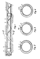
- Figure 1 shows a length of drill pipe situated in a drill string in a highly angulated wellbore having a helical ridge disposed thereabout wherein the drill string is terminated with a bit.
- Figure 2 shows a cross section of Figure 1 taken from left to right wherein the helical ridge has a hemispherical cross section.
- Figure 3 shows a cross section of Figure 1 along line 2 taken from left to right wherein the helical ridge has a trapezoidal cross section.
- Figure 4 shows a cross section taken along line 2 of Figure 1 from left to right wherein the helical ridge has a rectangular cross section.
- Figure 5 shows a length of drill pipe having a single helical ridge disposed thereabout.
- Figure 6 shows a length of drill pipe having two helical ridges disposed thereabout.
- Figure 7 shows a section of steel drill string having a helical ridge of trapezoidal cross section welded thereto wherein the helical ridge has an outer surface of a wear resistant material.
- Figure 8 shows a cross section of drill string comprised of a high strength composite wherein the helical ridge is integral therewith.
- Figure 1 shows a horizontal bore hole having a drill string terminated with a bit situated therein.
- the horizontal bore hole is a highly angulated example of the invention wherein there is 90° angulation from vertical.
- a drill string 3 terminated with a bit 4 which ejects drilling fluid is situated in the horizontal wellbore. It is powered to turn clockwise at the surface of the earth by a conventional rotary rig which injects drilling fluid down the hollow drill string, with ejection at the drill bit and flow back through the annulus around the drill string to the surface. The flow of the drilling fluid through the annulus serves to lubricate the drill string and to flush drill cuttings back to the surface.
- a length of drill pipe 5 having a helical ridge 6 disposed thereabout wherein the flight of the helical ridge is wound in the same direction as the rotation of the drill string is employed.
- rotation of the drill string moves the drill cuttings in a direction from the bit to the surface in the highly angulated wellbore, thus avoiding build-up of cuttings, stuck drill strings, much friction, and excessive wear.
- the height of the helical ridge above the surface of the drill pipe is 1 to 15 percent of the outer diameter of the drill string. More preferably, the height of the helical ridge is 1 to 10 percent of the outer diameter of the drill pipe.
- the helical ridge can have any of a variety of cross sectional shapes.
- Figure 2 taken along line 2-2 looking from the drill bit to the right shows a semi-hemispherical helical ridge 6 affixed to drill string 5 with welds 7.
- Figure 3 shows a helical ridge having trapezoidal cross section 60 affixed to drill string 5 by welds 7.
- Figure 4 shows a helical ridge 600 having rectangular cross section affixed to drill string 5 by welds 7.
- a plurality of lengths of drill pipe having a helical ridge disposed thereabout are employed.
- the ratio of drill pipes having a helical ridge to ordinary drill pipes in the drill string in the highly angulated wellbore ranges from at least 2 to substantially all of the drill pipes.
- angulated wellbore means a wellbore which is not more than 45° from horizontal, and includes wellbores which are 90° from vertical, or completely horizontal.
- the helical ridge has a length axial to the long axis of the drill pipe of 50 to 500 percent of the outer diameter of the drill pipe in a 360° rotation about the drill pipe.
- the height of the helical ridge is 2 to 8 percent of the outer diameter of the drill pipe
- a 360° rotation of the helical ridge has a length axial to the long axis of the drill pipe of 100 to 200 percent of the outer diameter of the drill pipe
- the width of the root of the helical ridge is 0.25 to 25 percent of the outer circumference of the drill pipe.
- Figure 5 shows a length of drill pipe which has a single helical ridge disposed thereabout.
- Figure 6 shows a similar length of drill pipe 5 having helical ridges 6 and 61 disposed thereabout in a double helix.
- the invention is not limited to any particular number of helixes disposed about the drill pipe, however, one to three is usually most practical.
- Figure 7 shows an embodiment of the invention wherein drill pipe 5 has a helical ridge 62 affixed thereto with welds 7.
- the helical ridge has an outer surface 8 of a wear resistant material disposed thereon.
- the wear resistant material can comprise carbon, aramid pulp, polytetrafluoroethylene, tungston carbide, a ceramic or the like which can be suspended in a resin or metal matrix binder, for example.
- Figure 8 shows yet another embodiment of the invention wherein drill pipe 55 has helical ridge 63 fabricated integral therewith.
- the drill pipe is fabricated of a high strength composite such as carbon fiber, aramid, or fiberglass reinforced thermoset polymer or thermoplastic.
- the length of drill pipe having the helical ridge disposed thereabout be the same length as other lengths of drill pipe. In some situations, it is even possible to use rather short lengths of drill pipe in the highly angulated wellbore.
- the root of the helical ridge be sufficiently wide that it can be securely affixed to the drill string such that it will not be torn loose in drilling operations.
- the width of the root of the helical ridge is 0.25 to 25 percent of the outer circumference of the drill pipe.
Landscapes
- Engineering & Computer Science (AREA)
- Life Sciences & Earth Sciences (AREA)
- Geology (AREA)
- Mining & Mineral Resources (AREA)
- Physics & Mathematics (AREA)
- Environmental & Geological Engineering (AREA)
- Fluid Mechanics (AREA)
- General Life Sciences & Earth Sciences (AREA)
- Geochemistry & Mineralogy (AREA)
- Mechanical Engineering (AREA)
- Earth Drilling (AREA)
Applications Claiming Priority (2)
| Application Number | Priority Date | Filing Date | Title |
|---|---|---|---|
| US07/498,864 US5042600A (en) | 1990-03-23 | 1990-03-23 | Drill pipe with helical ridge for drilling highly angulated wells |
| US498864 | 1990-03-23 |
Publications (2)
| Publication Number | Publication Date |
|---|---|
| EP0448397A2 true EP0448397A2 (de) | 1991-09-25 |
| EP0448397A3 EP0448397A3 (en) | 1992-09-02 |
Family
ID=23982825
Family Applications (1)
| Application Number | Title | Priority Date | Filing Date |
|---|---|---|---|
| EP19910302485 Withdrawn EP0448397A3 (en) | 1990-03-23 | 1991-03-21 | Method and apparatus for drilling a highly angulated wellbore |
Country Status (4)
| Country | Link |
|---|---|
| US (1) | US5042600A (de) |
| EP (1) | EP0448397A3 (de) |
| CA (1) | CA2037449A1 (de) |
| NO (1) | NO911167L (de) |
Cited By (3)
| Publication number | Priority date | Publication date | Assignee | Title |
|---|---|---|---|---|
| EP0541942A1 (de) * | 1991-11-09 | 1993-05-19 | Gd-Anker Gmbh | Bohrrohr |
| EP0823536A3 (de) * | 1996-06-18 | 1999-01-27 | George Swietlik | Zentriervorrichtung |
| CN102305033A (zh) * | 2011-08-05 | 2012-01-04 | 长安大学 | 一种旋挖钻机用钻斗 |
Families Citing this family (12)
| Publication number | Priority date | Publication date | Assignee | Title |
|---|---|---|---|---|
| NO953303L (no) * | 1994-08-26 | 1996-02-27 | Halliburton Co | Kompositt brönnproduksjonsrör |
| RU2227199C2 (ru) * | 2001-11-27 | 2004-04-20 | Дочернее общество с ограниченной ответственностью "Башнипинефть" Открытого акционерного общества "Акционерная нефтяная компания "Башнефть" | Колонна труб для бурения или эксплуатации горизонтальных и наклонно-направленных скважин |
| US20050067037A1 (en) * | 2003-09-30 | 2005-03-31 | Conocophillips Company | Collapse resistant composite riser |
| US20050100414A1 (en) * | 2003-11-07 | 2005-05-12 | Conocophillips Company | Composite riser with integrity monitoring apparatus and method |
| US7178611B2 (en) * | 2004-03-25 | 2007-02-20 | Cdx Gas, Llc | System and method for directional drilling utilizing clutch assembly |
| EP2212514B1 (de) * | 2007-10-03 | 2019-04-10 | M-I Llc | Bohrlochkratzer |
| US7814996B2 (en) * | 2008-02-01 | 2010-10-19 | Aquatic Company | Spiral ribbed aluminum drillpipe |
| US7984773B2 (en) * | 2008-05-13 | 2011-07-26 | Longyear Tm, Inc. | Sonic drill bit for core sampling |
| US7806204B2 (en) * | 2008-10-29 | 2010-10-05 | Longyear Tm, Inc. | Sonic drill rod with external surface features |
| US8820435B2 (en) * | 2010-10-13 | 2014-09-02 | Danuser Llc | Auger for digging holes |
| US20130062125A1 (en) * | 2011-09-13 | 2013-03-14 | James M. Savage | Apparatus and Method for Lateral Well Drilling |
| US9856699B2 (en) | 2014-03-18 | 2018-01-02 | Paul L. Anderson | Methods and apparatus for forming hole in ground |
Family Cites Families (23)
| Publication number | Priority date | Publication date | Assignee | Title |
|---|---|---|---|---|
| US1959367A (en) * | 1932-09-24 | 1934-05-22 | Charles B Kennedye | Well casing |
| US2210296A (en) * | 1939-09-23 | 1940-08-06 | Hardsocg Mfg Company | Means for connecting miners' extension drills |
| US2336029A (en) * | 1942-02-27 | 1943-12-07 | Texas Co | Well drilling apparatus |
| US2781185A (en) * | 1954-06-02 | 1957-02-12 | Robbins Davis | Drilling apparatus |
| US2815192A (en) * | 1955-11-18 | 1957-12-03 | Parrish Alan Jay | Earth boring auger section and cutter |
| FI30716A (fi) * | 1956-05-09 | 1959-11-10 | Jääpora | |
| US2981403A (en) * | 1957-04-15 | 1961-04-25 | Joy Mfg Co | Conveying apparatus |
| US3085639A (en) * | 1961-01-17 | 1963-04-16 | Earl L Fitch | Drill collar for oil wells |
| DE1236443B (de) * | 1963-06-18 | 1967-03-16 | Schmidt | Drehbohr- bzw. Spuelgestaenge fuer Gesteinsbohrarbeiten |
| US3656565A (en) * | 1970-09-23 | 1972-04-18 | Fred K Fox | Rotary drilling tool |
| US3833071A (en) * | 1973-05-03 | 1974-09-03 | R Koosman | Apparatus and process for soil dewatering |
| DE2506611A1 (de) * | 1975-02-17 | 1976-08-26 | Drespa Geb Biebersdorf Ursula | Drehbohrkopf fuer bohrungen mit hoher zielgenauigkeit |
| FR2375429A1 (fr) * | 1975-08-13 | 1978-07-21 | Eurotungstene | Tige allonge composite pour forage avec marteau hors de trou |
| US4049066A (en) * | 1976-04-19 | 1977-09-20 | Richey Vernon T | Apparatus for reducing annular back pressure near the drill bit |
| US4277869A (en) * | 1979-07-30 | 1981-07-14 | Hartwell Charles A | Stabilizer |
| CA1118755A (en) * | 1981-06-10 | 1982-02-23 | Legato Drilling Ltd. | Reverse action auger |
| US4543019A (en) * | 1982-07-28 | 1985-09-24 | Tokyo Shibaura Denki Kabushiki Kaisha | Boring tool |
| US4610316A (en) * | 1984-11-23 | 1986-09-09 | Lor, Inc. | Free flow stabilizer |
| FR2591654A1 (fr) * | 1985-12-16 | 1987-06-19 | Stenuick Freres | Dispositif de maintien de la rectitude d'un forage |
| US4771830A (en) * | 1987-05-01 | 1988-09-20 | Schlumberger Technology Corp. | Apparatus for positioning well tools in deviated well bores |
| DK165307C (da) * | 1987-06-04 | 1993-03-22 | Kurt Ingvard Soerensen | Sonde til maaling af den elektriske formationsmodstand i jordlag |
| US4883135A (en) * | 1987-09-18 | 1989-11-28 | Hawera Probst Gmbh & Co. | Apparatus for rock drill |
| CA1266043A (en) * | 1989-01-04 | 1990-02-20 | Ross W. Bracewell | Auger drilling system |
-
1990
- 1990-03-23 US US07/498,864 patent/US5042600A/en not_active Expired - Fee Related
-
1991
- 1991-03-01 CA CA002037449A patent/CA2037449A1/en not_active Abandoned
- 1991-03-21 EP EP19910302485 patent/EP0448397A3/en not_active Withdrawn
- 1991-03-22 NO NO91911167A patent/NO911167L/no unknown
Cited By (4)
| Publication number | Priority date | Publication date | Assignee | Title |
|---|---|---|---|---|
| EP0541942A1 (de) * | 1991-11-09 | 1993-05-19 | Gd-Anker Gmbh | Bohrrohr |
| US5388655A (en) * | 1991-11-09 | 1995-02-14 | Gruber; Heinz | Injection boring anchor with auger blade |
| EP0823536A3 (de) * | 1996-06-18 | 1999-01-27 | George Swietlik | Zentriervorrichtung |
| CN102305033A (zh) * | 2011-08-05 | 2012-01-04 | 长安大学 | 一种旋挖钻机用钻斗 |
Also Published As
| Publication number | Publication date |
|---|---|
| NO911167D0 (no) | 1991-03-22 |
| CA2037449A1 (en) | 1991-09-24 |
| US5042600A (en) | 1991-08-27 |
| EP0448397A3 (en) | 1992-09-02 |
| NO911167L (no) | 1991-09-24 |
Similar Documents
| Publication | Publication Date | Title |
|---|---|---|
| US5042600A (en) | Drill pipe with helical ridge for drilling highly angulated wells | |
| US5150757A (en) | Methods and apparatus for drilling subterranean wells | |
| US5148877A (en) | Apparatus for lateral drain hole drilling in oil and gas wells | |
| US5040620A (en) | Methods and apparatus for drilling subterranean wells | |
| EA018849B1 (ru) | Элемент бурового снаряда, бурильная труба и соответствующая колонна бурильных труб | |
| EP0778914B1 (de) | Installationsgerät eines futterrohres mit externen reibungsvermindernden mitteln | |
| US4658916A (en) | Method and apparatus for hydrocarbon recovery | |
| EP0251543A2 (de) | Stabilisator im Bohrloch | |
| US8851168B2 (en) | Performance centralizer for close tolerance applications | |
| US7954566B2 (en) | Stabilizer for drill strings | |
| US6125929A (en) | Casing cutter blade support sleeve | |
| CA2255179C (en) | Drilling motor drill bit reaming stabilizer | |
| MX2010008273A (es) | Tubo de perforacion de aluminio acanalado en espiral. | |
| US5042597A (en) | Horizontal drilling method and apparatus | |
| US6318480B1 (en) | Drilling of laterals from a wellbore | |
| CA2255288C (en) | Apparatus and method for stabilized downhole drilling motor | |
| CN104870743A (zh) | 支撑多分支窗的系统和方法 | |
| EP3942149B1 (de) | Bohrlochvorrichtung | |
| US9611846B2 (en) | Flow restrictor for a mud motor | |
| US20040060699A1 (en) | Torque reducing tubing component | |
| EP0248615A2 (de) | Bohrvorrichtung | |
| US4465146A (en) | Tubular drill string member with contoured circumferential surface | |
| US12006778B2 (en) | Non-rotating drill pipe protector tool having multiple types of hydraulic bearings | |
| AU725911B2 (en) | A drill pipe | |
| SU1694849A1 (ru) | Калибратор-интенсификатор |
Legal Events
| Date | Code | Title | Description |
|---|---|---|---|
| PUAI | Public reference made under article 153(3) epc to a published international application that has entered the european phase |
Free format text: ORIGINAL CODE: 0009012 |
|
| AK | Designated contracting states |
Kind code of ref document: A2 Designated state(s): DK FR GB IT NL |
|
| PUAL | Search report despatched |
Free format text: ORIGINAL CODE: 0009013 |
|
| AK | Designated contracting states |
Kind code of ref document: A3 Designated state(s): DK FR GB IT NL |
|
| 17P | Request for examination filed |
Effective date: 19921026 |
|
| 17Q | First examination report despatched |
Effective date: 19930615 |
|
| STAA | Information on the status of an ep patent application or granted ep patent |
Free format text: STATUS: THE APPLICATION IS DEEMED TO BE WITHDRAWN |
|
| 18D | Application deemed to be withdrawn |
Effective date: 19931026 |