EP0448475A1 - Magnometer with improved shield - Google Patents
Magnometer with improved shield Download PDFInfo
- Publication number
- EP0448475A1 EP0448475A1 EP91400775A EP91400775A EP0448475A1 EP 0448475 A1 EP0448475 A1 EP 0448475A1 EP 91400775 A EP91400775 A EP 91400775A EP 91400775 A EP91400775 A EP 91400775A EP 0448475 A1 EP0448475 A1 EP 0448475A1
- Authority
- EP
- European Patent Office
- Prior art keywords
- magnetometer according
- probe
- magnetometer
- shield
- hemispheres
- Prior art date
- Legal status (The legal status is an assumption and is not a legal conclusion. Google has not performed a legal analysis and makes no representation as to the accuracy of the status listed.)
- Ceased
Links
- 230000005291 magnetic effect Effects 0.000 claims abstract description 23
- 239000000523 sample Substances 0.000 claims description 21
- 238000003466 welding Methods 0.000 claims description 6
- BQCADISMDOOEFD-UHFFFAOYSA-N Silver Chemical compound [Ag] BQCADISMDOOEFD-UHFFFAOYSA-N 0.000 claims description 5
- 229910052709 silver Inorganic materials 0.000 claims description 5
- 239000004332 silver Substances 0.000 claims description 5
- 238000010894 electron beam technology Methods 0.000 claims description 4
- RYGMFSIKBFXOCR-UHFFFAOYSA-N Copper Chemical compound [Cu] RYGMFSIKBFXOCR-UHFFFAOYSA-N 0.000 claims description 3
- 229910052782 aluminium Inorganic materials 0.000 claims description 3
- XAGFODPZIPBFFR-UHFFFAOYSA-N aluminium Chemical compound [Al] XAGFODPZIPBFFR-UHFFFAOYSA-N 0.000 claims description 3
- 229910052802 copper Inorganic materials 0.000 claims description 3
- 239000010949 copper Substances 0.000 claims description 3
- 239000011324 bead Substances 0.000 claims description 2
- 229910052751 metal Inorganic materials 0.000 claims description 2
- 239000002184 metal Substances 0.000 claims description 2
- 230000001681 protective effect Effects 0.000 claims description 2
- 238000005259 measurement Methods 0.000 abstract description 10
- 230000003071 parasitic effect Effects 0.000 description 8
- 238000005481 NMR spectroscopy Methods 0.000 description 5
- 238000004804 winding Methods 0.000 description 3
- 230000005284 excitation Effects 0.000 description 2
- 239000003302 ferromagnetic material Substances 0.000 description 2
- 230000035699 permeability Effects 0.000 description 2
- 229920004943 Delrin® Polymers 0.000 description 1
- 230000005540 biological transmission Effects 0.000 description 1
- 230000000903 blocking effect Effects 0.000 description 1
- 239000003990 capacitor Substances 0.000 description 1
- 239000000969 carrier Substances 0.000 description 1
- 239000004020 conductor Substances 0.000 description 1
- 238000001514 detection method Methods 0.000 description 1
- 230000006866 deterioration Effects 0.000 description 1
- 238000010586 diagram Methods 0.000 description 1
- 230000005292 diamagnetic effect Effects 0.000 description 1
- 239000002889 diamagnetic material Substances 0.000 description 1
- 230000000694 effects Effects 0.000 description 1
- 230000005672 electromagnetic field Effects 0.000 description 1
- 230000005294 ferromagnetic effect Effects 0.000 description 1
- 239000000696 magnetic material Substances 0.000 description 1
- 238000004519 manufacturing process Methods 0.000 description 1
- 230000005298 paramagnetic effect Effects 0.000 description 1
- 239000002907 paramagnetic material Substances 0.000 description 1
- 244000045947 parasite Species 0.000 description 1
- 230000000284 resting effect Effects 0.000 description 1
- 238000005070 sampling Methods 0.000 description 1
- 239000013598 vector Substances 0.000 description 1
Images

Classifications
-
- G—PHYSICS
- G01—MEASURING; TESTING
- G01R—MEASURING ELECTRIC VARIABLES; MEASURING MAGNETIC VARIABLES
- G01R33/00—Arrangements or instruments for measuring magnetic variables
- G01R33/20—Arrangements or instruments for measuring magnetic variables involving magnetic resonance
- G01R33/28—Details of apparatus provided for in groups G01R33/44 - G01R33/64
- G01R33/42—Screening
- G01R33/421—Screening of main or gradient magnetic field
-
- G—PHYSICS
- G01—MEASURING; TESTING
- G01R—MEASURING ELECTRIC VARIABLES; MEASURING MAGNETIC VARIABLES
- G01R33/00—Arrangements or instruments for measuring magnetic variables
- G01R33/20—Arrangements or instruments for measuring magnetic variables involving magnetic resonance
- G01R33/24—Arrangements or instruments for measuring magnetic variables involving magnetic resonance for measuring direction or magnitude of magnetic fields or magnetic flux
Definitions
- the present invention relates to an improved shielded magnetometer. It finds an application in the precise measurement of slowly variable magnetic fields, in particular of the terrestrial magnetic field whose value is approximately 2,3.10 -5 to 7.10-a Tesla, according to the latitude.
- the magnetometer of the invention is either of the nuclear magnetic resonance oscillator type (R.M.N.) or of the electronic paramagnetic resonance oscillator type (R.P.E.). Such magnetometers are known and are described for example in French patent applications FR-A-2,583,887 and FR-A-2,603,384 respectively. It is therefore unnecessary to describe it in detail.
- a magnetometer is based on the principle of the magnetic resonance of protons or electrons, which, in the presence of a magnetic field B, precession around the direction of said field at a frequency F, called LARMOR frequency ", proportional to the modulus of B: where y denotes the gyromagnetic ratio of the proton or the electron.
- the resonance frequencies observed are situated between 1000 and 3000 Hertz for the NMR magmeters and between 0.7.10 8 and 2.108 Hertz for the EPR magnetometers
- magnetometers may see their performance deteriorated by the presence of spurious signals falling within the measurement range. It can be the harmonics of industrial frequencies (50 or 400 Hertz) for magnetometers with R.M.N. or radio waves for magnetometers at R.P.E.
- the presence of a notable field gradient (greater than 100 nanoTesla per meter) deteriorates the performance of a magnetometer at R.M.N.
- the R.P.E. magnetometer is much less sensitive to the gradient: the gradient must exceed 50 microTesla per meter to observe a deterioration of the signal.
- the technical problem posed (protection against electromagnetic electromagnetic fields, while allowing the transmission of continuous or slowly variable fields) finds a known solution in the shielding of the probe by a passive electromagnetic screen.
- Figure 1 attached shows, by way of example, a shielded NMR magnetometer probe according to an arrangement described in FR-A-2 583 887 already cited.
- the probe comprises two vials 20, 22 with radical solution. These two bottles are coated externally with a silver metallic layer, respectively 30 and 32, divided into non-contiguous sectors (to avoid circumferential eddy currents).
- the probe also comprises a central conductor formed by two half-sections 33a and 33b. The left end 34 of the section 33a is connected to the central core of a coaxial supply cable 36 while the right end 38 of the section 33b is connected to the conductive layer 32 of the bottle 22 by conductive strips 39.
- a tuning capacitor 50 is provided between the sections 33a and 33b.
- the sampling and excitation windings of this probe include two hemispherical windings 40 and 42 outside the resonator and, two flat coils 44 and 46 inside the resonator.
- the shielding of this probe is cylindrical in shape and consists of metallic strips 48 (for example in silver) deposited on an insulating support.
- the Applicant has thus been able to show that the parasitic field induced by rotation, in the case of a magnetometer provided with a cylindrical shielding of diameter 18 cm and length of 20 cm, is 400 picoTesla for a rotation speed of 1 degree per second while, for a magnetometer provided with a spherical shielding according to the invention, with a diameter of 30 cm, the parasitic induced field falls to 10 picoTesla for the same rotation speed, which represents a gain of one factor 40.
- Magnetic shielding consists of one or more layers of ferromagnetic materials, the relative permeability of which is high in front of the unit, which ensures attenuation of the magnetic field, even for continuous fields.
- an electromagnetic shield is formed from diamagnetic or paramagnetic materials (one or more layers) such as copper, silver, aluminum, whose relative permeability is very close to unity. The attenuation for continuous fields is then zero and it increases as the frequency increases.
- Electromagnetic shielding whose thickness is less than the skin thickness, behaves like a first-order low-pass filter (attenuation of 6 dB / octave). For a shielding thickness greater than the skin thickness, the attenuation increases faster.
- the spherical shape having been adopted in accordance with the invention, there remains to solve problems of another order, namely the practical realization of this shape.
- the invention recommends the use of two hemispheres assembled together around the probe.
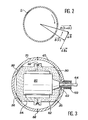
- Figure 2 shows why a spherical shield reduces the effect of the stray magnetic field induced by the rotation of the screen.
- a conductive sphere S is supposed to plunge into a uniform magnetic field B (t) , where is the time. If the sphere is rotated, this is equivalent, for the sphere, to rotating the field in the opposite direction. For the sphere, the field at time t + dt becomes B (t + dt) . Everything goes like this a field dB had come to compose with B (t) , field dB being substantially perpendicular to B (t) (as a first approximation).
- the variation of the field results in the appearance of induced currents in the sphere whose direction is such that the induced field dBi opposes the variation that gave birth to it (Lenz's law).
- This induced field is opposite to dB . It is therefore, too, substantially perpendicular to B (t) . Consequently, and always as a first approximation, the induced field does not significantly modify the field to be measured.
- the spherical shape means that this conclusion is valid whatever the orientation of the field B (t) .
- the shield and its magnetometer can therefore be rotated in any direction, the disturbance, which is already second order, will be the same regardless of the orientation of the shield relative to the field to be measured.
- Figure 3 shows an embodiment of a spherically shielded magnetometer according to the invention.
- the shielding consists, on the one hand, of a first hemisphere 60 pierced with an opening 62 serving as a passage for a power cable 64 and on the other hand, of a second hemisphere 70 assembled to the first.
- the first hemisphere 60 is connected to a queusot 100 disposed around the opening 62 and surrounding the supply cable 64 of the probe 80.
- the queusot 100 preferably has a length at least equal to its diameter. The longer the tail, the better the attenuation to the external alternating fields.
- the probe bears the reference 80. It can be of the NMR or RPE type. In the first case, it can be in accordance with that of FIG. 1.
- the probe is held in a non-magnetic insulating support formed by two assembled parts 82, 84 each disposed in one of the hemispheres and resting on the inner surface of those -this.
- the two hemispheres 60 and 70 are welded to each other over their entire thickness, along a cord 86.
- the two hemispheres are welded to each other by a weld bead obtained by electron beam.
- the welding temperature can be 600 ° C. Welding takes place over the entire thickness of the shield.
- each part 82 or 84 of the support includes grooves 90 on the surfaces bearing on the hemispheres.
- the support is surrounded by a ring 92 disposed under the weld line 86 of the two hemispheres 60 and 70, to protect the support during the electronic bombardment operation.
- the supports 82 and 84 are made of insulating and non-magnetic material, for example DELRIN (registered trademark).
- the diameter of the latter is preferably greater than 3 times the diameter of the probe.
- the shield 60, 80 is made of a metal such as aluminum, copper or silver.
Landscapes
- Physics & Mathematics (AREA)
- Condensed Matter Physics & Semiconductors (AREA)
- General Physics & Mathematics (AREA)
- Health & Medical Sciences (AREA)
- Epidemiology (AREA)
- Measuring Magnetic Variables (AREA)
- Superconductor Devices And Manufacturing Methods Thereof (AREA)
Abstract
Description
La présente invention a pour objet un magnétomètre à blindage perfectionné. Elle trouve une application dans la mesure précise des champs magnétiques lentement variables, notamment du champ magnétique terrestre dont la valeur est d'environ 2,3.10-5 à 7.10-a Tesla, selon la latitude.The present invention relates to an improved shielded magnetometer. It finds an application in the precise measurement of slowly variable magnetic fields, in particular of the terrestrial magnetic field whose value is approximately 2,3.10 -5 to 7.10-a Tesla, according to the latitude.
Le magnétomètre de l'invention est soit du type oscillateur à résonance magnétique nucléaire (R.M.N.), soit du type oscillateur à résonance paramagnétique électronique (R.P.E.). De tels magnétomètres sont connus et sont décrits par exemple dans les demandes de brevets français FR-A-2 583 887 et FR-A-2 603 384 respectivement. Il n'est donc pas utile de le décrire en détail.The magnetometer of the invention is either of the nuclear magnetic resonance oscillator type (R.M.N.) or of the electronic paramagnetic resonance oscillator type (R.P.E.). Such magnetometers are known and are described for example in French patent applications FR-A-2,583,887 and FR-A-2,603,384 respectively. It is therefore unnecessary to describe it in detail.
Il convient cependant de rappeler que le fonctionnement d'un magnétomètre repose sur le principe de la résonance magnétique des protons ou des électrons, qui, en présence d'un champ magnétique B, précessionnent autour de la direction dudit champ à une fréquence F, appelée fréquence de LARMOR ", proportionnelle au module de B :
Compte tenu des valeurs prises par le champ terrestre, les fréquences de résonance observées sont situées entre 1000 et 3000 Hertz pour les mag né- tomètres à R.M.N. et entre 0,7.108 et 2.108 Hertz pour les magnétomètres à R.P.E.Taking into account the values taken by the terrestrial field, the resonance frequencies observed are situated between 1000 and 3000 Hertz for the NMR magmeters and between 0.7.10 8 and 2.108 Hertz for the EPR magnetometers
Ces magnétomètres peuvent voir leurs performances détériorées par la présence de signaux parasites tombant dans la plage de mesure. Il peut s'agir des harmoniques des fréquences industrielles (50 ou 400 Hertz) pour les magnétomètres à R.M.N. ou des ondes radio pour les magnétomètres à R.P.E.These magnetometers may see their performance deteriorated by the presence of spurious signals falling within the measurement range. It can be the harmonics of industrial frequencies (50 or 400 Hertz) for magnetometers with R.M.N. or radio waves for magnetometers at R.P.E.
Par ailleurs, la présence d'un gradient de champ notable (supérieur à 100 nanoTesla par mètre) détériore les performances d'un magnétomètre à R.M.N. Le magnétomètre à R.P.E., quant à lui, est beaucoup moins sensible au gradient : le gradient doit excéder 50 microTesla par mètre pour observer une détérioration du signal.Furthermore, the presence of a notable field gradient (greater than 100 nanoTesla per meter) deteriorates the performance of a magnetometer at R.M.N. The R.P.E. magnetometer, on the other hand, is much less sensitive to the gradient: the gradient must exceed 50 microTesla per meter to observe a deterioration of the signal.
Il convient donc, si l'on cherche à optimiser le fonctionnement des magnétomètres, de les protéger au mieux contre les signaux parasites, tout en permettant la mesure des champs continus ou lentement variables (de 0 à 1 Hz) comme le champ magnétique terrestre.It is therefore advisable, if one seeks to optimize the operation of magnetometers, to protect them as best as possible against parasitic signals, while allowing the measurement of continuous or slowly variable fields (from 0 to 1 Hz) like the terrestrial magnetic field.
Le problème technique posé (protection contre les champs électromagnétiques aitematifs, tout en permettant la transmission des champs continus ou lentement variables) trouve une solution connue dans le blindage de la sonde par un écran passif électromagnétique.The technical problem posed (protection against electromagnetic electromagnetic fields, while allowing the transmission of continuous or slowly variable fields) finds a known solution in the shielding of the probe by a passive electromagnetic screen.
La figure 1 annexée montre, à titre d'exemple, une sonde de magnétomètre à RMN blindée selon une disposition décrite dans FR-A-2 583 887 déjà cité.Figure 1 attached shows, by way of example, a shielded NMR magnetometer probe according to an arrangement described in FR-A-2 583 887 already cited.
Telle que représentée, la sonde comprend deux flacons 20, 22 à solution radicalaire. Ces deux flacons sont revêtus extérieurement d'une couche métallique argentée, respectivement 30 et 32, divisée en secteurs non jointifs (pour éviter les courants de FOUCAULT circonférentiels). La sonde comprend encore un conducteur central formé de deux demi-tronçons 33a et 33b. L'extrémité gauche 34 du tronçon 33a est reliée à l'àme centrale d'un càble coaxial d'alimenta- fion 36 tandis que l'extrémité droite 38 du tronçon 33b est connectée à la couche conductrice 32 du flacon 22 par des bandes conductrices 39. Un condensateur d'accord 50 est prévu entre les tronçons 33a et 33b. Les enroulements de prélévement et d'excitation de cette sonde comprennent deux enroulements hémisphériques 40 et 42 extérieurs au résonateur et, deux bobines plates 44 et 46 intérieures au résonateur.As shown, the probe comprises two
Le blindage de cette sonde est de forme cylindrique et se compose de bandes métalliques 48 (par exemple en argent) déposées sur un support isolant.The shielding of this probe is cylindrical in shape and consists of metallic strips 48 (for example in silver) deposited on an insulating support.
Bien que donnant satisfaction à certains égards, un tel dispositif présente un inconvénient pour ce qui est du blindage. Il faut rappeler en effet que la mesure des variations du champ terrestre vise à détecter des anomalies magnétiques, signes de la présence, par exemple, d'une structure ferromagnétique immergée (navire ou autre). Les mesures s'effectuent à distance, la sonde étant embarquée sur un avion ou un hélicoptère. Or, de tels porteurs sont inévitablement soumis à des mouvements de rotation (roulis, tangage, lacet). Ces mouvements, appliqués au magnétomètre et à son blindage, provoquent l'apparition d'un champ magnétique parasite, induit par des courants de FOUCAULT circulant dans le blindage. Ce champ parasite perturbe la mesure du champ terrestre et nuit à la détection des anomalies.Although satisfactory in certain respects, such a device has a drawback with regard to shielding. It should be remembered that the measurement of variations in the Earth's field aims to detect magnetic anomalies, signs of the presence, for example, of an immersed ferromagnetic structure (ship or other). The measurements are carried out remotely, the probe being carried on an airplane or a helicopter. However, such carriers are inevitably subjected to rotational movements (roll, pitch, yaw). These movements, applied to the magnetometer and its shielding, cause the appearance of a parasitic magnetic field, induced by eddy currents flowing in the shielding. This parasitic field disturbs the measurement of the terrestrial field and interferes with the detection of anomalies.
D'une manière générale, il faut viser à ce que, la sonde blindée étant mise en rotation, elle ne voie pas ses performances dégradées par la présence d'un champ magnétique induit parasite. C'est le rôle du blindage. L'homme du métier ayant à le fabriquer, lui donne en général une forme cylindrique comme dans l'exemple de la figure 1, ou éventuellement parallèlé- pipédique, car ces formes sont commodes à réaliser.In general, it should be aimed at ensuring that, with the shielded probe in rotation, it does not see its performance degraded by the presence of a parasitic induced magnetic field. This is the role of armor. Those skilled in the art having to manufacture it, generally give it a cylindrical shape as in the example in FIG. 1, or possibly parallelepipedic, since these shapes are convenient to produce.
Or, le Demandeur a montré qu'avec de telles formes, dans l'application envisagée, les mouvements de rotation auxquels le blindage est soumis provoquent l'apparition d'un champ magnétique induit parasite non négligeable. Ce champ induit se compose avec le champ terrestre à mesurer et la mesure s'en trouve perturbée.However, the Applicant has shown that with such shapes, in the envisaged application, the rotational movements to which the shielding is subjected cause the appearance of a non-negligible parasitic induced magnetic field. This induced field is composed with the terrestrial field to be measured and the measurement is thereby disturbed.
La solution préconisée par le Demandeur est alors d'utiliser un blindage de forme sphérique. Un tel blindage, associé à une sonde de magnétomètre (à RMN ou à RPE) et soumis aux mouvements décrits précédemment, verra encore l'apparition d'un champ induit, mais dans ce cas, ce champ sera toujours perpendiculaire au champ terrestre à mesurer, comme on le comprendra mieux par la suite. Les deux vecteurs s'additionneront mais leur orthogonalité minimisera la perturbation.The solution recommended by the Applicant is then to use a shield of spherical shape. Such shielding, associated with a magnetometer probe (NMR or RPE) and subjected to the movements described above, will still see the appearance of an induced field, but in this case, this field will always be perpendicular to the terrestrial field to be measured. , as will be better understood later. The two vectors will add but their orthogonality will minimize the disturbance.
Le Demandeur a pu montrer ainsi que le champ parasite induit par rotation, dans le cas d'un magnétomètre muni d'un blindage cylindrique de diamètre 18 cm et de longueur de 20 cm, est de 400 picoTesla pour une vitesse de rotation de 1 degré par seconde tandis que, pour un magnétomètre muni d'un blindage sphérique conformément à l'invention, avec un diamètre de 30 cm, le champ induit parasite tombe à 10 picoTesla pour la même vitesse de rotation, ce qui représente un gain d'un facteur 40.The Applicant has thus been able to show that the parasitic field induced by rotation, in the case of a magnetometer provided with a cylindrical shielding of diameter 18 cm and length of 20 cm, is 400 picoTesla for a rotation speed of 1 degree per second while, for a magnetometer provided with a spherical shielding according to the invention, with a diameter of 30 cm, the parasitic induced field falls to 10 picoTesla for the same rotation speed, which represents a gain of one
Il faut observer, qu'en soi, un blindage sphérique n'est pas nouveau. Un tel blindage est décrit par exemple dans l'article de K. HIRAO et al. intitulé "Large Spherical Magnetic Shield Room", publié dans la revue "Jour. Geomag. Geoelectr.", vol. 37, 581-588,1985. Il faut souligner cependant que de tels blindages sont destinés à isoler complétement un laboratoire de mesure. Dans ces conditions, ces blindages présentent de très grandes dimensions (diamètre de 6 à 8 mètres) et sont composés de matériaux ferromagnétiques (donc à très haute permittivité) pour empêcher totalement le champ magnétique terrestre (ainsi que d'autres champs parasites extérieurs) de pénétrer dans le laboratoire de mesure. Il s'agit donc d'un blindage magnétique total.It should be noted that, in itself, spherical shielding is not new. Such shielding is described for example in the article by K. HIRAO et al. entitled "Large Spherical Magnetic Shield Room", published in the journal "Jour. Geomag. Geoelectr.", vol. 37, 581-588, 1985. It should be emphasized, however, that such shields are intended to completely isolate a measurement laboratory. Under these conditions, these shields have very large dimensions (diameter of 6 to 8 meters) and are composed of ferromagnetic materials (therefore with very high permittivity) to completely prevent the Earth's magnetic field (as well as other external parasitic fields) from enter the measurement laboratory. It is therefore a total magnetic shielding.
Dans le problème que se propose de résoudre l'invention, il ne s'agit certainement pas de bloquer le champ magnétique terrestre, puisque c'est justement le champ qu'il s'agit de mesurer. Le blindage ne doit donc pas être magnétique mais plutôt électromagnétique. Il faut rappeler à cet égard, la différence existant entre un blindage magnétique et un blindage électromagnétique. Un blindage magnétique est constitué d'une ou de plusieurs couches de matériaux ferromagnétiques, dont la perméabilité relative est grande devant l'unité, ce qui assure une atténuation du champ magnétique, même pour des champs continus. En revanche, un blindage électromagnétique est formé de matériaux (une ou plusieurs couches) diamagnétiques ou paramagnétiques comme le cuivre, l'argent, l'aluminium, dont la perméabilité relative est très proche de l'unité. L'atténuation pour les champs continus est alors nulle et elle va croissant à mesure que la fréquence augmente.In the problem which the invention proposes to solve, it is certainly not a question of blocking the terrestrial magnetic field, since it is precisely the field which it is a question of measuring. The shielding must therefore not be magnetic but rather electromagnetic. It should be remembered in this regard, the difference between a magnetic shielding and an electromagnetic shielding. Magnetic shielding consists of one or more layers of ferromagnetic materials, the relative permeability of which is high in front of the unit, which ensures attenuation of the magnetic field, even for continuous fields. On the other hand, an electromagnetic shield is formed from diamagnetic or paramagnetic materials (one or more layers) such as copper, silver, aluminum, whose relative permeability is very close to unity. The attenuation for continuous fields is then zero and it increases as the frequency increases.
Un blindage électromagnétique dont l'épaisseur est inférieure à l'épaisseur de peau, se comporte comme un filtre passe-bas du premier ordre (atténuation de 6 dB/octave). Pour une épaisseur de blindage supérieure à l'épaisseur de peau, l'atténuation augmente plus vite.Electromagnetic shielding whose thickness is less than the skin thickness, behaves like a first-order low-pass filter (attenuation of 6 dB / octave). For a shielding thickness greater than the skin thickness, the attenuation increases faster.
Pour en revenir au document antérieur relatif aux blindages sphériques, il faut souligner pour finir qu'il ne fait pas allusion, et pour cause, à la rotation du blindage. Les problèmes posés par cette rotation n'y sont donc pas été posés, et, corrélativement les avantages liés à la forme sphérique n'y sont pas mentionnés.To return to the previous document relating to spherical shields, it must finally be pointed out that it does not refer, and for good reason, to the rotation of the shielding. The problems posed by this rotation were therefore not posed there, and, correlatively, the advantages linked to the spherical shape are not mentioned there.
On peut donc dire, qu'en dépit d'une analogie de vocabulaire, le problème technique résolu dans cet art antérieur n'est pas celui que s'attache à résoudre l'invention.It can therefore be said that, despite a vocabulary analogy, the technical problem solved in this prior art is not that which the invention seeks to solve.
La forme sphérique ayant été adoptée conformément à l'invention, reste à résoudre des problèmes d'un autre ordre, à savoir la réalisation pratique de cette forme. L'invention préconise l'utilisation de deux hémisphères assemblés l'un à l'autre autour de la sonde.The spherical shape having been adopted in accordance with the invention, there remains to solve problems of another order, namely the practical realization of this shape. The invention recommends the use of two hemispheres assembled together around the probe.
De toute façon, les caractéristiques et avantages de l'invention apparaîtront mieux à la lumière de la description qui va suivre. Cette description porte sur des exemples de réalisation donnés à titre explicatif et nullement limitatif et elle se réfère à des dessins annexés sur lesquels :
- - la figure 1, déjà décrite, montre un magnétomètre de l'art antérieur ;
- - la figure 2 est un schéma montrant comment le champ réel et le champ parasite se composent ;
- - la figure 3 montre, en coupe, un magnétomètre à blindage sphérique selon l'invention.
- - Figure 1, already described, shows a magnetometer of the prior art;
- - Figure 2 is a diagram showing how the real field and the stray field are composed;
- - Figure 3 shows, in section, a magnetometer with spherical shielding according to the invention.
La figure 2 montre pourquoi un blindage sphérique réduit l'effet du champ magnétique parasite induit par la rotation de l'écran.Figure 2 shows why a spherical shield reduces the effect of the stray magnetic field induced by the rotation of the screen.
Une sphère conductrice S est supposée plonger dans un champ magnétique uniforme
La variation du champ se traduit par l'apparition de courants induits dans la sphère dont le sens est tel que le champ induit
La figure 3 montre un mode de réalisation d'un magnétomètre à blindage sphérique selon l'invention. Tel que représenté, le blindage est constitué, d'une part, d'un premier hémisphère 60 percé d'une ouverture 62 servant de traversée pour un câble d'alimentation 64 et d'autre part, d'un second hémisphère 70 assemblé au premier.Figure 3 shows an embodiment of a spherically shielded magnetometer according to the invention. As shown, the shielding consists, on the one hand, of a
Le premier hémisphère 60 est relié à un queusot 100 disposé autour de l'ouverture 62 et entourant le càble 64 d'alimentation de la sonde 80. Le queusot 100 a de préférence une longueur au moins égale à son diamètre. Plus le queusot est long, meilleure sera l'atténuation aux champs alternatifs extérieurs.The
La sonde porte la référence 80. Elle peut être du type RMN ou RPE. Dans le premier cas, elle peut être conforme à celle de la figure 1. La sonde est tenue dans un support isolant amagnétique formé de deux parties assemblées 82, 84 disposées chacune dans l'un des hémisphères et en appui sur la surface intérieure de ceux-ci.The probe bears the
Les deux hémisphères 60 et 70 sont soudés l'un à l'autre sur toute leur épaisseur, le long d'un cordon 86.The two
De préférence, les deux hémisphères sont soudés l'un à l'autre parun cordon de soudure obtenu par faisceau d'électrons. La température de soudage peut être de 600°C. La soudure s'effectue sur toute l'épaisseur du blindage.Preferably, the two hemispheres are welded to each other by a weld bead obtained by electron beam. The welding temperature can be 600 ° C. Welding takes place over the entire thickness of the shield.
Pour permettre l'établissement d'un vide partiel à l'intérieur du blindage lors de la soudure par faisceau d'électrons, chaque partie 82 ou 84 du support comprend des rainures 90 sur les surfaces en appui sur les hémisphères.To allow the establishment of a partial vacuum inside the shield during electron beam welding, each
Le support est entouré d'un anneau 92 disposé sous la ligne de soudure 86 des deux hémisphères 60 et 70, pour protéger le support lors de l'opération de bombardement électronique.The support is surrounded by a
Les supports 82 et 84 sont en matériau isolant et amagnétique, par exemple en DELRIN (marque déposée).The supports 82 and 84 are made of insulating and non-magnetic material, for example DELRIN (registered trademark).
Pour éviter que le champ créé dans la sonde par les enroulements d'excitation soit une source de courant induit dans le blindage, le diamètre de celui-ci est de préférence supérieur à 3 fois le diamètre de la sonde.To prevent the field created in the probe by the excitation windings from being a source of current induced in the shielding, the diameter of the latter is preferably greater than 3 times the diameter of the probe.
Le blindage 60, 80 est en un métal comme l'aluminium, le cuivre ou l'argent.The
Le montage des pièces illustrées s'effectue dans l'ordre suivant :
- 1) soudage de l'hémisphère 60 et du queusot 100 pour constituer un ensemble A ;
- 2) assemblage de la sonde 80 avec son câble 64 dans la partie 82 du support, pour constituer un ensemble B ;
- 3) montage de l'anneau de
protection 86 sur la partie 84 du support pour constituer un ensemble C ; - 4) assemblage des ensembles B et C pour constituer un ensemble D ;
- 5) assemblage des ensembles D et A pour constituer un ensemble E ;
- 6) enfin, assemblage par soudage de l'hémisphère 70 et de l'ensemble E.
- 1) welding the
hemisphere 60 and thequeusot 100 to form an assembly A; - 2) assembly of the
probe 80 with itscable 64 in thepart 82 of the support, to constitute an assembly B; - 3) mounting of the
protective ring 86 on thepart 84 of the support to constitute an assembly C; - 4) assembling sets B and C to form a set D;
- 5) assembly of sets D and A to form a set E;
- 6) finally, assembly by welding of the
hemisphere 70 and of the assembly E.
Claims (11)
Applications Claiming Priority (2)
| Application Number | Priority Date | Filing Date | Title |
|---|---|---|---|
| FR9003739 | 1990-03-23 | ||
| FR9003739A FR2660074B1 (en) | 1990-03-23 | 1990-03-23 | IMPROVED SHIELDED MAGNETOMETER. |
Publications (1)
| Publication Number | Publication Date |
|---|---|
| EP0448475A1 true EP0448475A1 (en) | 1991-09-25 |
Family
ID=9395048
Family Applications (1)
| Application Number | Title | Priority Date | Filing Date |
|---|---|---|---|
| EP91400775A Ceased EP0448475A1 (en) | 1990-03-23 | 1991-03-21 | Magnometer with improved shield |
Country Status (5)
| Country | Link |
|---|---|
| US (1) | US5187438A (en) |
| EP (1) | EP0448475A1 (en) |
| CA (1) | CA2038529A1 (en) |
| FR (1) | FR2660074B1 (en) |
| NO (1) | NO911171L (en) |
Cited By (1)
| Publication number | Priority date | Publication date | Assignee | Title |
|---|---|---|---|---|
| FR2723927A1 (en) * | 1994-08-24 | 1996-03-01 | Centre Nat Rech Scient | Receptacle for helium for use in magnetometers and neutron filters |
Families Citing this family (5)
| Publication number | Priority date | Publication date | Assignee | Title |
|---|---|---|---|---|
| FR2695484B1 (en) * | 1992-09-07 | 1994-10-14 | Commissariat Energie Atomique | NMR magnetometer probe with a single resonator and single radical solution. |
| FR2702279B1 (en) * | 1993-03-05 | 1995-04-07 | Commissariat Energie Atomique | Differential resonance magnetometer. |
| FR2702844B1 (en) * | 1993-03-16 | 1995-05-12 | Commissariat Energie Atomique | Directional digital resonance magnetometer. |
| FR2702845B1 (en) * | 1993-03-16 | 1995-04-28 | Commissariat Energie Atomique | Multiaxial resonance magnetometer. |
| RU2204152C2 (en) * | 2001-06-26 | 2003-05-10 | Военный инженерно-космический университет им. А.Ф.Можайского | Facility shielding magnetometers from magnetic fields of spacecraft and other objects |
Citations (3)
| Publication number | Priority date | Publication date | Assignee | Title |
|---|---|---|---|---|
| US4546317A (en) * | 1983-07-01 | 1985-10-08 | The United States Of America As Represented By The Secretary Of The Navy | Free nuclear precession gradiometer system |
| DE3438702A1 (en) * | 1984-10-23 | 1986-04-24 | Licentia Patent-Verwaltungs-Gmbh, 6000 Frankfurt | Electromagnetically screened chamber |
| EP0206931A1 (en) * | 1985-06-21 | 1986-12-30 | Commissariat A L'energie Atomique | NMR magnetometer probe with a centrally tuned cavity having a divided central cross-sectional slice |
Family Cites Families (2)
| Publication number | Priority date | Publication date | Assignee | Title |
|---|---|---|---|---|
| FR2213500B1 (en) * | 1972-09-20 | 1975-09-12 | Commissariat Energie Atomique | |
| US4504812A (en) * | 1983-06-07 | 1985-03-12 | Moermond Donald I | Spherical transformer apparatus |
-
1990
- 1990-03-23 FR FR9003739A patent/FR2660074B1/en not_active Expired - Lifetime
-
1991
- 1991-03-14 US US07/669,626 patent/US5187438A/en not_active Expired - Fee Related
- 1991-03-18 CA CA002038529A patent/CA2038529A1/en not_active Abandoned
- 1991-03-21 EP EP91400775A patent/EP0448475A1/en not_active Ceased
- 1991-03-22 NO NO91911171A patent/NO911171L/en unknown
Patent Citations (3)
| Publication number | Priority date | Publication date | Assignee | Title |
|---|---|---|---|---|
| US4546317A (en) * | 1983-07-01 | 1985-10-08 | The United States Of America As Represented By The Secretary Of The Navy | Free nuclear precession gradiometer system |
| DE3438702A1 (en) * | 1984-10-23 | 1986-04-24 | Licentia Patent-Verwaltungs-Gmbh, 6000 Frankfurt | Electromagnetically screened chamber |
| EP0206931A1 (en) * | 1985-06-21 | 1986-12-30 | Commissariat A L'energie Atomique | NMR magnetometer probe with a centrally tuned cavity having a divided central cross-sectional slice |
Non-Patent Citations (1)
| Title |
|---|
| Journal of geomagnetism and geoelectricity vol. 37, 1985, Tokyo, Japan pages 581 - 588; K.Hirao et al.: "Large spherical magnetic shield room" * |
Cited By (1)
| Publication number | Priority date | Publication date | Assignee | Title |
|---|---|---|---|---|
| FR2723927A1 (en) * | 1994-08-24 | 1996-03-01 | Centre Nat Rech Scient | Receptacle for helium for use in magnetometers and neutron filters |
Also Published As
| Publication number | Publication date |
|---|---|
| FR2660074A1 (en) | 1991-09-27 |
| US5187438A (en) | 1993-02-16 |
| CA2038529A1 (en) | 1991-09-24 |
| NO911171L (en) | 1991-09-24 |
| NO911171D0 (en) | 1991-03-22 |
| FR2660074B1 (en) | 1992-06-12 |
Similar Documents
| Publication | Publication Date | Title |
|---|---|---|
| EP0646806B1 (en) | Open magnetic structure | |
| EP0156659B1 (en) | Electric current measuring device using a regularly shaped toroidal solenoid | |
| EP0109867B1 (en) | Sensitive broad band alternating magnetic field detector, and its use as a measuring apparatus | |
| CA1278027C (en) | Device for correcting the magnetic field inhomogeneities in a magnet by means of magnetic elements | |
| US20100219347A1 (en) | Mr/pet imaging systems | |
| EP0445017B1 (en) | Coaxial resonator with distributed tuning capacity | |
| WO2016142439A1 (en) | Current sensor for measuring an alternating current | |
| JP3273648B2 (en) | NMR probe | |
| EP0448475A1 (en) | Magnometer with improved shield | |
| FR2621125A1 (en) | GRADIENT COIL SYSTEM FOR NMR MACHINE | |
| FR2622017A1 (en) | ELECTRIC CURRENT SENSOR DEVICE | |
| EP4127737B1 (en) | Rogowski current sensor which is fast and immune to voltage drifts | |
| EP0326477A1 (en) | Air flow direction sensor with an electromagnetic damping and positioning device | |
| FR2743148A1 (en) | DEVICE AND METHOD FOR MONITORING TUBES BY EDGE CURRENT | |
| EP2649464A1 (en) | Method for characterizing a solid sample by nmr spectrometry, and apparatus for implementing said method | |
| EP0451054B1 (en) | Compact NMR probe | |
| EP2902758A1 (en) | Photon radiation detector comprising an array of antennas and a spiral resistive support | |
| EP0206931B1 (en) | Nmr magnetometer probe with a centrally tuned cavity having a divided central cross-sectional slice | |
| US5568049A (en) | Fiber optic faraday flux transformer sensor and system | |
| EP0324292A1 (en) | Continuous vector magnetometer with a capacitive magnetostrictive sensor, and its use as a gradient meter | |
| WO2007085772A1 (en) | Electromagnetic sensor for a rotating member rotational speed | |
| EP0543434B1 (en) | Magnetic head with a system of coils compensating magnetic leakage | |
| FR2799840A1 (en) | Differential current sensor for detecting faults on electrical circuits, comprises inner ring core with compensating measurement windings enclosed by trunking with further compensating windings | |
| WO2000063716A1 (en) | Method for determining the permeability of a magnetic material by coaxial line perturbation | |
| CH499785A (en) | Spin Coupled Oscillator Type Nuclear Magnetic Resonance Magnetometer |
Legal Events
| Date | Code | Title | Description |
|---|---|---|---|
| PUAI | Public reference made under article 153(3) epc to a published international application that has entered the european phase |
Free format text: ORIGINAL CODE: 0009012 |
|
| AK | Designated contracting states |
Kind code of ref document: A1 Designated state(s): DE GB IT SE |
|
| 17P | Request for examination filed |
Effective date: 19920227 |
|
| 17Q | First examination report despatched |
Effective date: 19920820 |
|
| STAA | Information on the status of an ep patent application or granted ep patent |
Free format text: STATUS: THE APPLICATION HAS BEEN REFUSED |
|
| 18R | Application refused |
Effective date: 19930208 |