EP0448844A1 - Dispositif convoyeur de moissonneuse-batteuse pour accoupler le tablier de coupe à l'unité de base - Google Patents
Dispositif convoyeur de moissonneuse-batteuse pour accoupler le tablier de coupe à l'unité de base Download PDFInfo
- Publication number
- EP0448844A1 EP0448844A1 EP90200718A EP90200718A EP0448844A1 EP 0448844 A1 EP0448844 A1 EP 0448844A1 EP 90200718 A EP90200718 A EP 90200718A EP 90200718 A EP90200718 A EP 90200718A EP 0448844 A1 EP0448844 A1 EP 0448844A1
- Authority
- EP
- European Patent Office
- Prior art keywords
- feeder house
- front face
- assembly
- body portion
- face assembly
- Prior art date
- Legal status (The legal status is an assumption and is not a legal conclusion. Google has not performed a legal analysis and makes no representation as to the accuracy of the status listed.)
- Granted
Links
- 239000000463 material Substances 0.000 claims abstract description 20
- 238000005188 flotation Methods 0.000 claims description 18
- 230000000712 assembly Effects 0.000 claims description 17
- 238000000429 assembly Methods 0.000 claims description 17
- 238000003306 harvesting Methods 0.000 claims description 9
- 238000007789 sealing Methods 0.000 claims description 4
- 239000004575 stone Substances 0.000 description 5
- 235000010469 Glycine max Nutrition 0.000 description 2
- 244000068988 Glycine max Species 0.000 description 2
- 240000008042 Zea mays Species 0.000 description 2
- 235000002017 Zea mays subsp mays Nutrition 0.000 description 2
- 230000006835 compression Effects 0.000 description 2
- 238000007906 compression Methods 0.000 description 2
- 238000010276 construction Methods 0.000 description 2
- 230000014759 maintenance of location Effects 0.000 description 2
- 235000005824 Zea mays ssp. parviglumis Nutrition 0.000 description 1
- 235000016383 Zea mays subsp huehuetenangensis Nutrition 0.000 description 1
- 230000006978 adaptation Effects 0.000 description 1
- 239000004464 cereal grain Substances 0.000 description 1
- 235000013339 cereals Nutrition 0.000 description 1
- 235000005822 corn Nutrition 0.000 description 1
- 238000006073 displacement reaction Methods 0.000 description 1
- 230000002349 favourable effect Effects 0.000 description 1
- 230000009191 jumping Effects 0.000 description 1
- 235000009973 maize Nutrition 0.000 description 1
- 238000004904 shortening Methods 0.000 description 1
- 230000000087 stabilizing effect Effects 0.000 description 1
Images
Classifications
-
- A—HUMAN NECESSITIES
- A01—AGRICULTURE; FORESTRY; ANIMAL HUSBANDRY; HUNTING; TRAPPING; FISHING
- A01D—HARVESTING; MOWING
- A01D41/00—Combines, i.e. harvesters or mowers combined with threshing devices
- A01D41/12—Details of combines
- A01D41/14—Mowing tables
Definitions
- the present invention relates generally to crop harvesting machines, commonly referred to as combines, and, more particularly to providing a feeder house for mounting a header on a combine harvester base unit and which gives flexibility to adjusting the position of the header both relative to the ground and to conveyor means in the feeder house.
- Combines are equipped to utilize a variety of crop gathering headers, including headers specifically designed for harvesting maize (USA : corn), cereal grains or soy beans.
- headers specifically designed for harvesting maize (USA : corn), cereal grains or soy beans.
- these headers are attached to the forward end of the feeder house, which is a structure used to convey crop material from the header to the combine base unit for further harvesting treatment.
- the feeder house structure is rectangular in shape and includes a rectangular crop inlet opening at the forward end.
- Lateral flotation of the header has an increasingly greater importance with the increasing sizes of crop gathering headers because the larger headers are more susceptible to changes in the ground contour in that a ground contour change could result in one end of the header being above the crop material with no crop being harvested.
- To provide the header with the capability to float, and thereby follow the ground contour enables the header to gather more crop material and reduce losses.
- feeder houses of this type still face a problem in that the crop transfer from the header to the feeder house sometimes is less than fully satisfactory due to the distance between the header auger and the forwardmost portion of the feeder house crop conveying means differing, for a plurality of reasons, from the ideal distance which itself even may change under varying circumstances. It indeed has been found that the distance between the header auger and said conveying means in the feeder house is critical and that a deviation from the ideal relative positions of these components detrimentally affects the efficiency of the feeder house conveying means in engaging crop material to feed it rearwadly.
- a feeder house which is adapted for detachably mounting a crop harvesting header on a mobile combine harvester base unit and which includes :
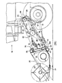
- FIG. 1 a schematic side elevational view, partially in cross section, of the forward portion of a crop harvesting machine 10, commonly referred to as self-propelled combine harvester, can be seen.
- the combine base unit 11 is mobilely supported by a wheeled frame 12 for movement over a field to harvest crop material. Pivotally mounted to the front of the base unit 11 is a feeder house 30 on which is mounted a crop harvesting header 20.
- the combine base unit 11 and the header 20 are conventional and the former is only fragmentarily shown in Figure 1.
- the header 20 includes a forwardly disposed crop cutting means in the form of a reciprocating type mower 21 for severing crop material from the stubble.
- a reel 22 is disposed above and forwardly of the cutting means 21 to sweep crop material over the cutting means 21 and transport it rearwardly to consolidating means in the form of a consolidating auger 23.
- the consolidating auger 23 converges crop material towards a centrally disposed crop discharge opening 24 for discharge into the inlet end 31 of the feeder house 30 where the crop material is engaged by a crop elevator 32 of conventional construction and conveyed to the discharge end 33 of the feeder house 30 and fed into a conventional threshing and separating mechanism (not shown) supported in the base unit 11.
- the frame 25 of the header 20 includes a transversely disposed main header beam 26 which is used to support the header 20 from the feeder house 30.
- Varying the angle of the cutting means 21 relative to the ground (as can be seen in phantom in Figure 1) on the one hand and lateral flotation of the header 20 relative to the base unit 11 for permitting this header 20 to adapt to transverse ground unevennesses, on the other hand, can be important to the efficiency of the crop gathering operation of the header 20 in connection with losses of crop material in different types of crops.
- the header 20 is supported on the feeder house 30 via a mounting assembly 70 which basically consists of a front face assembly 75, which is adjustable relative to the feeder house 30 to accomodate said cutting angle adjustability, and a cradle assembly 101 which is pivotally mounted on the front face assembly 75 to accomodate said lateral flotation.
- the feeder house 30 includes a generally fore-and-aft extending, elongated body portion 34 defined by said rearward or discharge end 33 pivotally attached to the base unit 11 and said forward or inlet end 31 adjacent the header 20 for connection thereto.
- the body portion 34 includes a passageway 35 therethrough terminating in a crop inlet opening 37 at the forward end 31 and a crop discharge opening 29 at the discharge end 33 for allowing crop material to be transported rearwardly from said forward end 31 to said rearward end 33.
- the crop elevator or conveying means normally in the form of an endless chain and slat apron conveyor 32, is positioned within the passageway 35 for transporting the crop material rearwardly.
- the apron conveyor 32 is driven by a drive shaft 39 positioned at the rearward end 33.
- a driven shaft (not shown) adjacent the forward end 31 supports guide wheels, idler sprockets or a drum 41 around which the endless apron conveyor 32 extends and which enables this conveyor 32 to rotate into an operative position for transporting crop material rearwardly.
- the height of the header 20 relative to the ground is controlled by a pair of header lift hydraulic cylinders 14 interconnecting the feeder house 30 and the base unit 11. By extending the header lift cylinders 14 and pivoting the feeder house 30 about the drive shaft 39, the header 20 can be lifted from the ground.
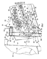
- the driven shaft is mounted on the same side walls 36 via the intermediary of apron conveyor tensioning assemblies 40 including a.o. mounting arms 45 which can be seen in Figure 2 and which permit both generally fore-and-aft adjustment and generally up-and-down movement of said driven shaft.
- the mounting arms 45 are generally elongate in shape and are provided adjacent the inner sides of the feeder house side walls 36 and have bearings (not shown) generally at their forward ends for rotatably supporting the driven shaft.
- the arms 45 have rearward pivot pins 46 which extend outwardly through generally fore-and-aft oriented elongated slots 47 in the feeder house side walls 36 and which are supported, via angled brackets 48, on tension rods 49 disposed externally alongside the feeder house side walls 36. These tension rods 49, in turn, axially movably are received in mounting brackets 50 secured on said side walls 36.
- a tensioning spring in the form of a compression coil spring 51 extends around each tension rod 49 between the corresponding mounting bracket 50 and an adjustable stop 52 on said rod 49 and is disposed to urge the corresponding mounting arm 45 with the driven shaft mounted thereon, in a forward direction thereby taking up the slack of, and compensating for the wear in the apron conveyor 32.
- the adjustable stops 52 on the tension rods 49 from time to time need some adjustment to maintain appropriate tension in the apron conveyor 32. It also will be appreciated that, as wear progresses, the positions of the driven shaft shifts in a forward direction whereby the forewardmost section 43 of the path 42 of the apron conveyor 32 is displaced in the same direction thus coming closer to the extreme forward end of the feeder house 30 and to the header auger 23.
- the pivot pins 46 firmly may be connected to the corresponding feeder house side walls 36 by lock nuts 53 and appropriate washers 54 used to tightly fasten the angled brackets 48 to the corresponding feeder house side walls 36. It will be appreciated that, in case these fastening nuts 53 and washers 54 are used, the apron tensioning is not accomplished automatically in as much as these fastening nuts 53 and washers 54 need to be released and refastened from time to time.
- the driven shaft not only is mounted for fore-and-aft adjustment within the feeder house 30, as described hereabove, but also in a manner permitting up-and-down flotational movement relative to the feeder house bottom wall 38.
- a flotation assembly 60 each one of which comprises a mounting pin 61 secured to the corresponding mounting arm 45 (which equally is part of the flotation assembly 60) and extending outwardly through an appropriate aperture 62 in the corresponding feeder house side wall 36.
- a tension rod 63 is pivotally coupled to each one of these pins 61 and extends through an apertured bracket 64 secured to the corresponding feeder house side wall 36.
- a flotation spring in the form of a compression coil spring 65 extending around each tension rod 63 is supported, at one of its ends, on the corresponding apertured bracket 64 and abuts, at its opposite end, against an adjustable stop 66 on said tension rod 63.
- a further, resilient stop 67 also is provided on each tension rod 63 at the side of the corresponding apertured bracket 64 opposite to the side thereof against which the coil spring 65 abuts.
- the arrangement is such that, when not in use, the coil springs 65 position the driven shaft at a minimum distance above the feeder house floor 38 with the resilient stop means 67 abutting against the corresponding apertured brackets 64.
- the coil springs 65 permit the driven shaft and the forward portion 43 of the apron conveyor 32 to resiliently float away from the feeder house floor 38 when a thick crop layer passes through the gap between said floor 38 and the lower, operative strand of the apron conveyor 32 thus both accommodating the passage of this thick layer of crop material and improving the grip of the apron conveyor 32 thereon.
- the mounting assembly 70 basically consists of a front face assembly 75 and a cradle assembly 101 pivotally supported on the front face assembly 75.
- the front face assembly 75 is a separate, generally rectangular structure defining an opening 74 therein which matches around the inlet opening 37 of the feeder house forward end 31 to which it adjustably is connected.
- This assembly 75 includes an uper offset section in the form of a generally L-shaped, transverse beam 76 which is substantially registrable with the main header beam 26 for supporting the header 20 in a detachable, operable position.
- the front face assembly 75 further also includes transversely opposite side sheets 77 which project rearwardly in close proximity to the feeder house side walls 36 and which include a plurality of generally upright, elongated apertures 78 which, as seen in side view, overlap generally fore-and-aft extending, elongated apertures 80 in the feeder house side walls 36.
- Bolts 79, interfitting corresponding apertures 78 and 80 at their intersections, serve to restrict and control the extent of movement of the front face assembly 75 and to act as a stabilizing means.
- upper and lower adjustment assemblies 81, 82 also are provided at the transversely opposite sides of the feeder house 30 between the side sheets 77 and the feeder house side walls 36.
- These assemblies 81, 82 comprise screwed rods 83, 90 which, at one end, pivotally are attached to the corresponding side sheets 77 and adjustably extend through and are connected, along their length, to apertured supports 84, 94 on the corresponding feeder house side walls 36.
- Each upper screwed rod 83 is pivotally connected, at said one end thereof, to a lug 85 welded to a flanged portion 86 of the corresponding side sheet 77 and is connected to said corresponding support 84 via the intermediary of a pair of adjustment nuts 88 on the rod 83 at opposite sides of said support 84.
- a spherical member 89, slid on the upper rod 83, is interposed beween the rearwardmost one of the nuts 88 and the support 84 which is curved in shape to seat said spherical member 89.
- Each lower screwed rod 90 is pivotally couplet at its forward end to the corresponding side sheet 77 of the front face assembly 75 via a bushing 91 which fits on a mounting pin 92 extending transversely outwardly from said side sheet 77.
- Adjustment nuts 93 are provided on each rod 90 at opposite sides of the corresponding support 94 which is in the form of a flange welded to the corresponding feeder house side wall 36 and through which said screwed rod 90 adjustably extends.
- the front face assembly 75 finally also comprises a lower transverse beam 72 which completes the rectangular shape thereof and which is in the form of a generally upside-down, generally U-shaped profile positioned generally at the level and forwardly of the intake edge 28 of the feeder bottom wall 38.
- This lower transverse beam 72 is positioned generally at the level of the feeder house floor 38 and, in as much as, in use, crop material passes thereacross into the gap between the apron conveyor 32 and the floor 38 and furthermore, as the front face assembly 75 is both angularly and fore-and-aft adjustable relative to the body portion 34 of the feeder house 30, a resilient sealing plate 73 has been provided which, at one edge, is coupled to said lower beam 72 and which adjustably overlaps the forward or intake edge 28 of the feeder bottom wall 38 in resilient, sealing engagement therewith; the arrangement being such that this sealing plate 73 does not interfere with the adjustablility of the front face assembly 75.
- the header 20 detachably can be connected directly to this front face assembly 75.
- the mounting assembly 70 necessarily also will comprise a cradle assembly 101 which pivotally is mounted on the front face assembly 75.
- the separate cradle assembly 101 is pivotally affixed to the front face assembly 75 for rotation in front of said front face assembly 75 about the direction of travel.
- the cradle assemby 101 is pivotally affixed to the center of the transverse L-shaped beam 76 of the front face assembly 75 by a pivot means 110.
- the cradle assembly 101 includes a crop passage opening 102 which is registrable with the header discharge opening 24 and further also generally matches with the opening 74 in the front face assembly 75.
- the cradle assembly 101 also includes a nesting portion 103 which overlaps the offset section or L-shape of the upper beam 76 of the front face assembly 75 for receiving and attaching the main header beam 26.
- the nesting portion 103 has a preferred, substantially U-shaped configuration with the forward leg 104 being shorter than the rear leg 105 and bent forwardly for facilitating the connection between the main header beam 26 and the nesting portion 103.
- locking means (not shown) are provided to lock the beam 26 into an operative position wherein th crop discharge opening 24, the crop passage openings 102 and 74 and the crop inlet opening 37 are substantially aligned.
- a latch mechanism (also not shown) locks the lower end 106 of the cradle assembly 101 to the corresponding portion of the header 20 to further aid in retaining the header 20 in an operative position relative to the cradle assembly 101 and the feeder house body portion 34.
- a pivot control means (not shown) may be provided between the cradle assembly 101 and the front face assembly 75.
- the crop passage opening 102 therethrough becomes slightly askewed to the opening 74 in the front face assembly 75 and the crop inlet opening 37 at the beginning of the feeder house passageway 35.
- this does not present a problem to the crop flow from the header 20 to the feeder house body portion 34. Details of a pivot control means for the cradle assembly 101 may be found in EU-A-o.243.530 to which reference is made.
- the cradle assembly 101 also includes a forwardly projecting crop retention hood 115 which overlaps the forwardmost portion 43 if the apron conveyor path 42 and which, when a header 20 is mounted on the feeder house 30, extends into the discharge opening 24 of this header 20 and into the vicinity of the header auger 23 to retain crop material within the feeder house passageway 35.
- the cradle assembly 101 includes retaining means (equally not shown) which interact between the lower portion 106 of the cradle assembly 101 and the front face of the front face assembly 75 without however interferring with the pivotal movement of the cradle assembly 101 relative to the front face assembly 75.
- a combine with a combined header mounting assembly 70 including both a lateral float mechanism in the form of the cradle assembly 101 and a front face assembly 75 which both is generally fore-and-aft adjustable relative to the feeder house body portion 34 and pivotable relative to said body portion 34 around a transverse pivot axis, one skilled in the art should readily realize that a very flexible header mounting combination is obtained.
- This arrangement also obviates the need to shorten the apron conveyor chains with one or two links when these chains have lengthened as a result of wear and which is the conventional approach to avoid interference of the apron conveyor 32 with other parts such as e.g. the auger 23 when wear results in the forward shaft being displaced too far to the front.
- this conventional approach very much restricts the possibility for accurately controlling the spacing beween the header auger 23 and the apron conveyor 32, i.e. this spacing often either is too small or too big while that the ideal spacing cannot be obtained by means of varying the number of links of the conveyor chains.
- apron conveyor 32 Shortening the apron conveyor chains by taking out one or more links furthermore even is totally unacceptable in case the apron conveyor 32 has to cooperate with a toothed stone deflector drum (not shown) which may be installed within the envelope of said conveyor 32 inside the feeder house body portion 34 in a manner so that the teeth thereof extend from within said envelope through the gaps inbetween adjacent apron slats 44, to the space between the lower strand of the apron conveyor 32 and the feeder house floor 38.
- a toothed stone deflector drum not shown
- the teeth of such a stone deflector drum may be arranged to intermesh with the slats 44 of the apron conveyor 32 and this implies that all slats 44 are equidistantly spaced apart along the length of the conveyor chains as otherwise this deflector drum and the conveyor slats 44 would foul each other. Taking out one or a few links from the conveyor chains would result in the slats 44 no longer being equidistantly spaced apart around the circumference of the apron conveyor 32.
- the arrangement described also permits to maintain adequate tension in the apron conveyor 32 without having to fear that the forward shaft will be displaced too far to the front (which, as already said, would result in the apron conveyor 32 fouling certain other machine parts such as the header auger 23).
- This adequate apron tension prevents said apron from jumping over any teeth of the drive sprockets on the drive shaft 39.
- the arrangement described so far is advantageous when different headers have to be mounted on the feeder house 30 in as much as it is conceivable that, different headers may have different geometric configurations and more specifically, that in different headers the header auger may be spaced further away from, respectively positioned closer to the header rear wall 27 and the discharge opening 24 therein. Indeed, wide headers often require a larger spacing between the header rear wall 27 and the header auger 23 than narrow or small headers. Yet, the spacing between the header auger 23 and the apron conveyor 32 in the feeder house 30 preferably always should be minimal irrespective of the header size to guarantee a smooth transfer of the crop material from the header 20 to the feeder house 30. It thus will be appreciated that the adjustability provided by the front face assembly 75 described hereabove also provides the desired flexibility for perfectly adapting the feeder house 30 to different headers 20 having different header frame-header auger configurations.
- the front faced assembly 75 described so far also enables easy adjustment of the cutting angle of the header 20. Indeed, adjustment of only the upper screwed rods 83 relative to the supports 84 results in a tilting of the front face assembly 75 and thus also of the header 20 about the pivot points 92 of the lower adjustment assemblies 82.
- pivot pins 92 are positioned on the side sheets 77 generally in alignment witht the forward, driven shaft of the feeder house 30 and when ignoring the limited adjustability of this shaft. This is why said driven shaft is not visible in the drawings. It further also will be appreciated that this is advantageous for keeping the clearance between the header auger 23 and the apron conveyor 32 generally constant during said cutting angle adjustment.
- the bolts 79 are tightened to firmly hold the front face assembly 75 and the header 20 in the selected position and thus to stabilize the feeder house and header combination.
- the forward or driven feeder shaft is mounted in a manner to be fore-and-aft adjustable in unison with the front face assembly 75.
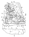
- the front face assembly 75 additionally is provided with transversely spaced apart flanges 121 which extend rearwardly from the forward face of the front face assembly 75 within the passageway 35 of the feeder house body portion 34 and closely alongside the side walls 36 thereof.
- each additional flange 121 extends parallel to the corresponding side sheet 77 at a small distance inwardly therefrom and in a manner so as to receive the corresponding body portion side wall 36 therebetween when the front face assembly is mounted in an operative position on the feeder house body portion 34.
- Pivot pins 122 extend transversely inwardly from the flanges 121 adjacent the rearward ends thereof and pivotally support the mounting arms 45 which, as in the preferred embodiment rotatably sypport the forward feeder shaft at their forward ends.
- the driven feeder shaft in this alternative embodiment also is mounted for up-and-down flotational movement.
- the mounting pins 61 of the flotation assemblies 60 extend transversely outwardly through generally upright and elongated apertures 123 in the additional flanges 121 and through the generally rectangularly shaped apertures 62 in the body portion side walls 36.
- the flotation assemblies 60 of this alternative arrangement are very similar to the flotation assemblies 60 of the preferred embodiment with the only major difference being that, in the alternative arrangement, these assemblies resiliently support on the side sheets 77 of the front face assembly 75 rather than on the feeder house side walls 36.
- the forward portion 43 of the conveyor path 42 always is at the same relative position to the crop retention hood 115 and it will be appreciated that preferably the spacing therebween is minimal. Also, when the apron conveyor 32 lengthens as a result of wear, the front face assembly 75 is shifted in the forward direction to take up the slack arisen in the apron conveyor 32 because of this wear.
- the alternative arrangement according to Figure 3 basically has the same advantages as the preferred embodiment according to Figure 2, except that this alternative embodiment does not permit adaptation to headers with different auger-rear wall configurations.
- the alternative embodiment also permits easy cutting angle adjustment by tilting the front face assembly 75 around the mouting pins 92.
- the alternative embodiment also has the additional advantage of the further increased simplicity which results from the fact that the front feeder shaft is supported on the front face assembly 75 whereby both components are adjusted in unison.
Landscapes
- Life Sciences & Earth Sciences (AREA)
- Environmental Sciences (AREA)
- Harvester Elements (AREA)
Priority Applications (2)
| Application Number | Priority Date | Filing Date | Title |
|---|---|---|---|
| DE1990605290 DE69005290T2 (de) | 1990-03-27 | 1990-03-27 | Mähdrescher-Elevator zum Anschliessen der Mähwerksplattform an der Basis-Einheit. |
| EP19900200718 EP0448844B1 (fr) | 1990-03-27 | 1990-03-27 | Dispositif convoyeur de moissonneuse-batteuse pour accoupler le tablier de coupe à l'unité de base |
Applications Claiming Priority (1)
| Application Number | Priority Date | Filing Date | Title |
|---|---|---|---|
| EP19900200718 EP0448844B1 (fr) | 1990-03-27 | 1990-03-27 | Dispositif convoyeur de moissonneuse-batteuse pour accoupler le tablier de coupe à l'unité de base |
Publications (2)
| Publication Number | Publication Date |
|---|---|
| EP0448844A1 true EP0448844A1 (fr) | 1991-10-02 |
| EP0448844B1 EP0448844B1 (fr) | 1993-12-15 |
Family
ID=8204976
Family Applications (1)
| Application Number | Title | Priority Date | Filing Date |
|---|---|---|---|
| EP19900200718 Expired - Lifetime EP0448844B1 (fr) | 1990-03-27 | 1990-03-27 | Dispositif convoyeur de moissonneuse-batteuse pour accoupler le tablier de coupe à l'unité de base |
Country Status (2)
| Country | Link |
|---|---|
| EP (1) | EP0448844B1 (fr) |
| DE (1) | DE69005290T2 (fr) |
Cited By (18)
| Publication number | Priority date | Publication date | Assignee | Title |
|---|---|---|---|---|
| US5338518A (en) * | 1991-07-09 | 1994-08-16 | Institute Francais Du Petrole | Distillation-reaction apparatus and its use for carrying out balanced reaction |
| DE4320979A1 (de) * | 1993-06-24 | 1995-01-05 | Kloeckner Humboldt Deutz Ag | Wechseleinheiten für Erntemaschinen |
| FR2738987A1 (fr) * | 1995-09-01 | 1997-03-28 | Schwaninger Kurt Ag | Moissonneuse-batteuse pour terrain en pente |
| EP1040750A1 (fr) * | 1999-04-01 | 2000-10-04 | New Holland Belgium N.V. | Convoyeur de moissonneuse-batteuse |
| EP1044595A1 (fr) | 1999-04-14 | 2000-10-18 | Deere & Company | Assemblage de convoyeur |
| EP1621064A1 (fr) * | 2004-07-26 | 2006-02-01 | CLAAS Selbstfahrende Erntemaschinen GmbH | Conveyeur-élévateur pour une machine agricole |
| EP1849352A1 (fr) * | 2006-04-26 | 2007-10-31 | Deere & Company | Système de transport double pour compartiment d'alimentation d'une moissonneuse-batteuse |
| EP2071934A1 (fr) * | 2007-12-22 | 2009-06-24 | Maschinenfabrik Kemper GmbH & Co. KG | Machine destinée à la récolte de plantes de type à tiges |
| AU2010241336B2 (en) * | 2000-09-01 | 2013-02-28 | Midwest Fabrication Pty Ltd | Combine harvesters |
| EP2989882A1 (fr) * | 2014-08-29 | 2016-03-02 | Deere & Company | Arrangement d'un convoyeur incliné pour le montage d'un tête de coupe sur une moissonneuse-batteuse |
| EP3090616A1 (fr) * | 2015-05-06 | 2016-11-09 | CLAAS Selbstfahrende Erntemaschinen GmbH | Reglage d'angle de coupe d'une barre de coupe |
| US9538707B2 (en) | 2014-07-11 | 2017-01-10 | Cnh Industrial America Llc | Harvester header with belt length adapting mechanism |
| US20200128746A1 (en) * | 2018-10-31 | 2020-04-30 | Deere And Company | Harvester feeder |
| CN112042389A (zh) * | 2019-06-05 | 2020-12-08 | 丰疆智能科技股份有限公司 | 收割机及其喂入装置和喂入方法 |
| US20210127584A1 (en) * | 2019-10-30 | 2021-05-06 | Agco Do Brasil Soluções Agrícolas Ltda. | Adjustable stop for feeder house drum |
| US20220312676A1 (en) * | 2021-03-31 | 2022-10-06 | Cnh Industrial America Llc | Belt drive for driving the header of a combine harvester |
| EP4136958A1 (fr) * | 2021-08-19 | 2023-02-22 | CNH Industrial Belgium NV | Appareil et procédé de réglage de plaque frontale d'un dispositif d'alimentation pour véhicule agricole |
| CN117242978A (zh) * | 2023-11-17 | 2023-12-19 | 山西农业大学 | 一种双链齿式谷物联合收割机割台 |
Families Citing this family (1)
| Publication number | Priority date | Publication date | Assignee | Title |
|---|---|---|---|---|
| US5918448A (en) * | 1997-02-06 | 1999-07-06 | Agco Corporation | Combine header lateral tilt assembly |
Citations (7)
| Publication number | Priority date | Publication date | Assignee | Title |
|---|---|---|---|---|
| GB1105386A (en) * | 1964-06-26 | 1968-03-06 | Massey Ferguson Ltd | Combine having quick detachable header |
| DE1582366A1 (de) * | 1966-11-15 | 1970-04-30 | Massey Ferguson Australia Ltd | Maehdrescher |
| US3981125A (en) * | 1975-02-12 | 1976-09-21 | International Harvester Company | Leveling mechanism for harvester headers |
| US4266391A (en) * | 1979-11-05 | 1981-05-12 | Sperry Corporation | Header attachment mechanism for combines |
| US4362005A (en) * | 1981-07-16 | 1982-12-07 | Allis-Chalmers Corporation | Tensioning mechanism for feeder conveyor positioned within feeder housing |
| EP0094807A1 (fr) * | 1982-05-14 | 1983-11-23 | Chamberlain John Deere Pty. Ltd. | Connexion entre conduits |
| US4707972A (en) * | 1985-06-19 | 1987-11-24 | New Holland Inc. | Movable feeder floor for combines |
-
1990
- 1990-03-27 EP EP19900200718 patent/EP0448844B1/fr not_active Expired - Lifetime
- 1990-03-27 DE DE1990605290 patent/DE69005290T2/de not_active Expired - Fee Related
Patent Citations (7)
| Publication number | Priority date | Publication date | Assignee | Title |
|---|---|---|---|---|
| GB1105386A (en) * | 1964-06-26 | 1968-03-06 | Massey Ferguson Ltd | Combine having quick detachable header |
| DE1582366A1 (de) * | 1966-11-15 | 1970-04-30 | Massey Ferguson Australia Ltd | Maehdrescher |
| US3981125A (en) * | 1975-02-12 | 1976-09-21 | International Harvester Company | Leveling mechanism for harvester headers |
| US4266391A (en) * | 1979-11-05 | 1981-05-12 | Sperry Corporation | Header attachment mechanism for combines |
| US4362005A (en) * | 1981-07-16 | 1982-12-07 | Allis-Chalmers Corporation | Tensioning mechanism for feeder conveyor positioned within feeder housing |
| EP0094807A1 (fr) * | 1982-05-14 | 1983-11-23 | Chamberlain John Deere Pty. Ltd. | Connexion entre conduits |
| US4707972A (en) * | 1985-06-19 | 1987-11-24 | New Holland Inc. | Movable feeder floor for combines |
Cited By (26)
| Publication number | Priority date | Publication date | Assignee | Title |
|---|---|---|---|---|
| US5338518A (en) * | 1991-07-09 | 1994-08-16 | Institute Francais Du Petrole | Distillation-reaction apparatus and its use for carrying out balanced reaction |
| DE4320979A1 (de) * | 1993-06-24 | 1995-01-05 | Kloeckner Humboldt Deutz Ag | Wechseleinheiten für Erntemaschinen |
| FR2738987A1 (fr) * | 1995-09-01 | 1997-03-28 | Schwaninger Kurt Ag | Moissonneuse-batteuse pour terrain en pente |
| EP1040750A1 (fr) * | 1999-04-01 | 2000-10-04 | New Holland Belgium N.V. | Convoyeur de moissonneuse-batteuse |
| EP1044595A1 (fr) | 1999-04-14 | 2000-10-18 | Deere & Company | Assemblage de convoyeur |
| US6318058B1 (en) | 1999-04-14 | 2001-11-20 | Deere & Company | Feeder house |
| AU2010241336B2 (en) * | 2000-09-01 | 2013-02-28 | Midwest Fabrication Pty Ltd | Combine harvesters |
| AU2010241336B8 (en) * | 2000-09-01 | 2013-06-27 | Midwest Fabrication Pty Ltd | Combine harvesters |
| EP1621064A1 (fr) * | 2004-07-26 | 2006-02-01 | CLAAS Selbstfahrende Erntemaschinen GmbH | Conveyeur-élévateur pour une machine agricole |
| EP1849352A1 (fr) * | 2006-04-26 | 2007-10-31 | Deere & Company | Système de transport double pour compartiment d'alimentation d'une moissonneuse-batteuse |
| US7905078B2 (en) | 2007-12-22 | 2011-03-15 | Deere & Company | Machine for the harvest of stalk-like plants |
| EP2071934A1 (fr) * | 2007-12-22 | 2009-06-24 | Maschinenfabrik Kemper GmbH & Co. KG | Machine destinée à la récolte de plantes de type à tiges |
| US9538707B2 (en) | 2014-07-11 | 2017-01-10 | Cnh Industrial America Llc | Harvester header with belt length adapting mechanism |
| EP2989882A1 (fr) * | 2014-08-29 | 2016-03-02 | Deere & Company | Arrangement d'un convoyeur incliné pour le montage d'un tête de coupe sur une moissonneuse-batteuse |
| US9468148B2 (en) | 2014-08-29 | 2016-10-18 | Deere & Company | Feederhouse arrangement for mounting a header to a combine |
| EP3090616A1 (fr) * | 2015-05-06 | 2016-11-09 | CLAAS Selbstfahrende Erntemaschinen GmbH | Reglage d'angle de coupe d'une barre de coupe |
| US20200128746A1 (en) * | 2018-10-31 | 2020-04-30 | Deere And Company | Harvester feeder |
| US10945373B2 (en) * | 2018-10-31 | 2021-03-16 | Deere & Company | Harvester feeder |
| CN112042389A (zh) * | 2019-06-05 | 2020-12-08 | 丰疆智能科技股份有限公司 | 收割机及其喂入装置和喂入方法 |
| US20210127584A1 (en) * | 2019-10-30 | 2021-05-06 | Agco Do Brasil Soluções Agrícolas Ltda. | Adjustable stop for feeder house drum |
| US20220312676A1 (en) * | 2021-03-31 | 2022-10-06 | Cnh Industrial America Llc | Belt drive for driving the header of a combine harvester |
| US11497166B2 (en) * | 2021-03-31 | 2022-11-15 | Cnh Industrial America Llc | Belt drive for driving the header of a combine harvester |
| EP4136958A1 (fr) * | 2021-08-19 | 2023-02-22 | CNH Industrial Belgium NV | Appareil et procédé de réglage de plaque frontale d'un dispositif d'alimentation pour véhicule agricole |
| US12102038B2 (en) | 2021-08-19 | 2024-10-01 | Cnh Industrial America Llc | Apparatus and method for adjusting faceplate of feeder for agricultural vehicle |
| CN117242978A (zh) * | 2023-11-17 | 2023-12-19 | 山西农业大学 | 一种双链齿式谷物联合收割机割台 |
| CN117242978B (zh) * | 2023-11-17 | 2024-01-26 | 山西农业大学 | 一种双链齿式谷物联合收割机割台 |
Also Published As
| Publication number | Publication date |
|---|---|
| DE69005290T2 (de) | 1994-04-28 |
| EP0448844B1 (fr) | 1993-12-15 |
| DE69005290D1 (de) | 1994-01-27 |
Similar Documents
| Publication | Publication Date | Title |
|---|---|---|
| EP0448844B1 (fr) | Dispositif convoyeur de moissonneuse-batteuse pour accoupler le tablier de coupe à l'unité de base | |
| US6330782B1 (en) | Front drum adjustment mechanism for a feederhouse on an agricultural combine | |
| US8573388B2 (en) | Conveyor belt tensioner for an agricultural harvesting header | |
| US4266392A (en) | Header cutting angle adjustment mechanism | |
| US8230670B2 (en) | Flexible combine harvester draper header with pivoting structure within side draper | |
| US4266391A (en) | Header attachment mechanism for combines | |
| CA1125037A (fr) | Mecanisme separateur par flottation pour moissonneuse-batteuse | |
| US4531351A (en) | Adjustable multiple row harvester head assembly | |
| EP3878266B1 (fr) | Positionnement de diviseur de hauteur pour une moissonneuse agricole | |
| US4463546A (en) | Windrow pickup mechanism | |
| US6640527B2 (en) | Center feed finger adjustment mechanism for header | |
| US11589512B2 (en) | Draper support for a draper belt assembly of an agricultural harvester | |
| US3699753A (en) | Quick-adjustable lower stop for feeder house drum | |
| CA2298202C (fr) | Logement pour dispositif d'alimentation | |
| US20050262821A1 (en) | Curved support arm for reel assembly | |
| US2126072A (en) | Ensilage harvester | |
| US11412658B2 (en) | Torsion balanced harvester head | |
| JP2000041470A (ja) | 穀稈供給搬送装置 | |
| JPH06189619A (ja) | コンバイン刈取部の株元搬送装置 | |
| JP2021023118A (ja) | 収穫機 | |
| JPH10136752A (ja) | コンバインの下部搬送チエンガイド | |
| JPH11289845A (ja) | コンバインの穀稈搬送供給装置 | |
| JP2006254772A (ja) | コンバインの刈取装置 |
Legal Events
| Date | Code | Title | Description |
|---|---|---|---|
| PUAI | Public reference made under article 153(3) epc to a published international application that has entered the european phase |
Free format text: ORIGINAL CODE: 0009012 |
|
| 17P | Request for examination filed |
Effective date: 19900327 |
|
| AK | Designated contracting states |
Kind code of ref document: A1 Designated state(s): DE FR GB |
|
| 17Q | First examination report despatched |
Effective date: 19930127 |
|
| RAP1 | Party data changed (applicant data changed or rights of an application transferred) |
Owner name: NEW HOLLAND BELGIUM N.V. |
|
| GRAA | (expected) grant |
Free format text: ORIGINAL CODE: 0009210 |
|
| AK | Designated contracting states |
Kind code of ref document: B1 Designated state(s): DE FR GB |
|
| REF | Corresponds to: |
Ref document number: 69005290 Country of ref document: DE Date of ref document: 19940127 |
|
| ET | Fr: translation filed | ||
| PLBE | No opposition filed within time limit |
Free format text: ORIGINAL CODE: 0009261 |
|
| STAA | Information on the status of an ep patent application or granted ep patent |
Free format text: STATUS: NO OPPOSITION FILED WITHIN TIME LIMIT |
|
| 26N | No opposition filed | ||
| REG | Reference to a national code |
Ref country code: GB Ref legal event code: IF02 |
|
| REG | Reference to a national code |
Ref country code: FR Ref legal event code: CD |
|
| PGFP | Annual fee paid to national office [announced via postgrant information from national office to epo] |
Ref country code: GB Payment date: 20080114 Year of fee payment: 19 |
|
| PGFP | Annual fee paid to national office [announced via postgrant information from national office to epo] |
Ref country code: DE Payment date: 20080126 Year of fee payment: 19 Ref country code: FR Payment date: 20080108 Year of fee payment: 19 |
|
| GBPC | Gb: european patent ceased through non-payment of renewal fee |
Effective date: 20090327 |
|
| REG | Reference to a national code |
Ref country code: FR Ref legal event code: ST Effective date: 20091130 |
|
| PG25 | Lapsed in a contracting state [announced via postgrant information from national office to epo] |
Ref country code: DE Free format text: LAPSE BECAUSE OF NON-PAYMENT OF DUE FEES Effective date: 20091001 |
|
| PG25 | Lapsed in a contracting state [announced via postgrant information from national office to epo] |
Ref country code: GB Free format text: LAPSE BECAUSE OF NON-PAYMENT OF DUE FEES Effective date: 20090327 Ref country code: FR Free format text: LAPSE BECAUSE OF NON-PAYMENT OF DUE FEES Effective date: 20091123 |