EP0448936B1 - Procédé d'assemblage d'une pièce rapportée et d'un engin de glisse sur neige et ensemble constitué par un engin de glisse et une pièce rapporteé - Google Patents
Procédé d'assemblage d'une pièce rapportée et d'un engin de glisse sur neige et ensemble constitué par un engin de glisse et une pièce rapporteé Download PDFInfo
- Publication number
- EP0448936B1 EP0448936B1 EP19910101395 EP91101395A EP0448936B1 EP 0448936 B1 EP0448936 B1 EP 0448936B1 EP 19910101395 EP19910101395 EP 19910101395 EP 91101395 A EP91101395 A EP 91101395A EP 0448936 B1 EP0448936 B1 EP 0448936B1
- Authority
- EP
- European Patent Office
- Prior art keywords
- sliding device
- ski
- attached element
- thermofusible material
- attached
- Prior art date
- Legal status (The legal status is an assumption and is not a legal conclusion. Google has not performed a legal analysis and makes no representation as to the accuracy of the status listed.)
- Expired - Lifetime
Links
- 238000000034 method Methods 0.000 title claims abstract description 52
- 239000000463 material Substances 0.000 claims abstract description 70
- 238000002844 melting Methods 0.000 claims abstract description 7
- 230000008018 melting Effects 0.000 claims abstract description 7
- 239000010410 layer Substances 0.000 claims description 45
- 239000011248 coating agent Substances 0.000 claims description 14
- 238000000576 coating method Methods 0.000 claims description 14
- 238000003466 welding Methods 0.000 claims description 14
- 238000010438 heat treatment Methods 0.000 claims description 7
- 239000004952 Polyamide Substances 0.000 claims description 4
- 229920002647 polyamide Polymers 0.000 claims description 4
- 229910052799 carbon Inorganic materials 0.000 claims description 3
- 239000010409 thin film Substances 0.000 claims description 3
- 239000012790 adhesive layer Substances 0.000 claims 1
- 230000001680 brushing effect Effects 0.000 claims 1
- 238000001125 extrusion Methods 0.000 claims 1
- 238000010791 quenching Methods 0.000 claims 1
- 230000000171 quenching effect Effects 0.000 claims 1
- 239000012768 molten material Substances 0.000 abstract description 2
- 239000012943 hotmelt Substances 0.000 description 31
- 239000004959 Rilsan Substances 0.000 description 11
- 230000002787 reinforcement Effects 0.000 description 10
- 230000004927 fusion Effects 0.000 description 7
- 239000000835 fiber Substances 0.000 description 6
- 230000001012 protector Effects 0.000 description 6
- 229910052782 aluminium Inorganic materials 0.000 description 3
- XAGFODPZIPBFFR-UHFFFAOYSA-N aluminium Chemical compound [Al] XAGFODPZIPBFFR-UHFFFAOYSA-N 0.000 description 3
- 238000000429 assembly Methods 0.000 description 3
- 239000002131 composite material Substances 0.000 description 3
- 230000000694 effects Effects 0.000 description 3
- 239000010408 film Substances 0.000 description 3
- 229910052751 metal Inorganic materials 0.000 description 3
- 239000002184 metal Substances 0.000 description 3
- 239000004033 plastic Substances 0.000 description 3
- 229920003023 plastic Polymers 0.000 description 3
- 238000007590 electrostatic spraying Methods 0.000 description 2
- 239000007788 liquid Substances 0.000 description 2
- 239000011159 matrix material Substances 0.000 description 2
- 239000000203 mixture Substances 0.000 description 2
- 230000000750 progressive effect Effects 0.000 description 2
- 230000003014 reinforcing effect Effects 0.000 description 2
- 238000002791 soaking Methods 0.000 description 2
- 229920001169 thermoplastic Polymers 0.000 description 2
- 239000004416 thermosoftening plastic Substances 0.000 description 2
- OKTJSMMVPCPJKN-UHFFFAOYSA-N Carbon Chemical compound [C] OKTJSMMVPCPJKN-UHFFFAOYSA-N 0.000 description 1
- 229920000571 Nylon 11 Polymers 0.000 description 1
- 229920000299 Nylon 12 Polymers 0.000 description 1
- 239000004760 aramid Substances 0.000 description 1
- 229920003235 aromatic polyamide Polymers 0.000 description 1
- 238000005452 bending Methods 0.000 description 1
- 239000012141 concentrate Substances 0.000 description 1
- 238000001816 cooling Methods 0.000 description 1
- 238000005034 decoration Methods 0.000 description 1
- 238000005553 drilling Methods 0.000 description 1
- 239000011521 glass Substances 0.000 description 1
- 239000007924 injection Substances 0.000 description 1
- 238000002347 injection Methods 0.000 description 1
- 238000004519 manufacturing process Methods 0.000 description 1
- 235000011837 pasties Nutrition 0.000 description 1
- 230000035515 penetration Effects 0.000 description 1
- 229920000642 polymer Polymers 0.000 description 1
- 229920002635 polyurethane Polymers 0.000 description 1
- 239000004814 polyurethane Substances 0.000 description 1
- 238000000926 separation method Methods 0.000 description 1
- 230000035939 shock Effects 0.000 description 1
- 239000007787 solid Substances 0.000 description 1
- 238000007711 solidification Methods 0.000 description 1
- 230000008023 solidification Effects 0.000 description 1
- 239000002344 surface layer Substances 0.000 description 1
- 229920001187 thermosetting polymer Polymers 0.000 description 1
- 230000003313 weakening effect Effects 0.000 description 1
- 239000002023 wood Substances 0.000 description 1
Images

Classifications
-
- A—HUMAN NECESSITIES
- A63—SPORTS; GAMES; AMUSEMENTS
- A63C—SKATES; SKIS; ROLLER SKATES; DESIGN OR LAYOUT OF COURTS, RINKS OR THE LIKE
- A63C5/00—Skis or snowboards
- A63C5/12—Making thereof; Selection of particular materials
-
- A—HUMAN NECESSITIES
- A63—SPORTS; GAMES; AMUSEMENTS
- A63C—SKATES; SKIS; ROLLER SKATES; DESIGN OR LAYOUT OF COURTS, RINKS OR THE LIKE
- A63C9/00—Ski bindings
-
- B—PERFORMING OPERATIONS; TRANSPORTING
- B29—WORKING OF PLASTICS; WORKING OF SUBSTANCES IN A PLASTIC STATE IN GENERAL
- B29C—SHAPING OR JOINING OF PLASTICS; SHAPING OF MATERIAL IN A PLASTIC STATE, NOT OTHERWISE PROVIDED FOR; AFTER-TREATMENT OF THE SHAPED PRODUCTS, e.g. REPAIRING
- B29C37/00—Component parts, details, accessories or auxiliary operations, not covered by group B29C33/00 or B29C35/00
- B29C37/0078—Measures or configurations for obtaining anchoring effects in the contact areas between layers
- B29C37/0082—Mechanical anchoring
-
- B—PERFORMING OPERATIONS; TRANSPORTING
- B29—WORKING OF PLASTICS; WORKING OF SUBSTANCES IN A PLASTIC STATE IN GENERAL
- B29C—SHAPING OR JOINING OF PLASTICS; SHAPING OF MATERIAL IN A PLASTIC STATE, NOT OTHERWISE PROVIDED FOR; AFTER-TREATMENT OF THE SHAPED PRODUCTS, e.g. REPAIRING
- B29C65/00—Joining or sealing of preformed parts, e.g. welding of plastics materials; Apparatus therefor
- B29C65/02—Joining or sealing of preformed parts, e.g. welding of plastics materials; Apparatus therefor by heating, with or without pressure
- B29C65/06—Joining or sealing of preformed parts, e.g. welding of plastics materials; Apparatus therefor by heating, with or without pressure using friction, e.g. spin welding
- B29C65/0609—Joining or sealing of preformed parts, e.g. welding of plastics materials; Apparatus therefor by heating, with or without pressure using friction, e.g. spin welding characterised by the movement of the parts to be joined
- B29C65/0618—Linear
-
- B—PERFORMING OPERATIONS; TRANSPORTING
- B29—WORKING OF PLASTICS; WORKING OF SUBSTANCES IN A PLASTIC STATE IN GENERAL
- B29C—SHAPING OR JOINING OF PLASTICS; SHAPING OF MATERIAL IN A PLASTIC STATE, NOT OTHERWISE PROVIDED FOR; AFTER-TREATMENT OF THE SHAPED PRODUCTS, e.g. REPAIRING
- B29C66/00—General aspects of processes or apparatus for joining preformed parts
- B29C66/01—General aspects dealing with the joint area or with the area to be joined
- B29C66/05—Particular design of joint configurations
- B29C66/10—Particular design of joint configurations particular design of the joint cross-sections
- B29C66/11—Joint cross-sections comprising a single joint-segment, i.e. one of the parts to be joined comprising a single joint-segment in the joint cross-section
- B29C66/112—Single lapped joints
- B29C66/1122—Single lap to lap joints, i.e. overlap joints
-
- B—PERFORMING OPERATIONS; TRANSPORTING
- B29—WORKING OF PLASTICS; WORKING OF SUBSTANCES IN A PLASTIC STATE IN GENERAL
- B29C—SHAPING OR JOINING OF PLASTICS; SHAPING OF MATERIAL IN A PLASTIC STATE, NOT OTHERWISE PROVIDED FOR; AFTER-TREATMENT OF THE SHAPED PRODUCTS, e.g. REPAIRING
- B29C66/00—General aspects of processes or apparatus for joining preformed parts
- B29C66/01—General aspects dealing with the joint area or with the area to be joined
- B29C66/05—Particular design of joint configurations
- B29C66/10—Particular design of joint configurations particular design of the joint cross-sections
- B29C66/11—Joint cross-sections comprising a single joint-segment, i.e. one of the parts to be joined comprising a single joint-segment in the joint cross-section
- B29C66/114—Single butt joints
-
- B—PERFORMING OPERATIONS; TRANSPORTING
- B29—WORKING OF PLASTICS; WORKING OF SUBSTANCES IN A PLASTIC STATE IN GENERAL
- B29C—SHAPING OR JOINING OF PLASTICS; SHAPING OF MATERIAL IN A PLASTIC STATE, NOT OTHERWISE PROVIDED FOR; AFTER-TREATMENT OF THE SHAPED PRODUCTS, e.g. REPAIRING
- B29C66/00—General aspects of processes or apparatus for joining preformed parts
- B29C66/01—General aspects dealing with the joint area or with the area to be joined
- B29C66/05—Particular design of joint configurations
- B29C66/10—Particular design of joint configurations particular design of the joint cross-sections
- B29C66/12—Joint cross-sections combining only two joint-segments; Tongue and groove joints; Tenon and mortise joints; Stepped joint cross-sections
- B29C66/124—Tongue and groove joints
- B29C66/1242—Tongue and groove joints comprising interlocking undercuts
- B29C66/12423—Dovetailed interlocking undercuts
-
- B—PERFORMING OPERATIONS; TRANSPORTING
- B29—WORKING OF PLASTICS; WORKING OF SUBSTANCES IN A PLASTIC STATE IN GENERAL
- B29C—SHAPING OR JOINING OF PLASTICS; SHAPING OF MATERIAL IN A PLASTIC STATE, NOT OTHERWISE PROVIDED FOR; AFTER-TREATMENT OF THE SHAPED PRODUCTS, e.g. REPAIRING
- B29C66/00—General aspects of processes or apparatus for joining preformed parts
- B29C66/01—General aspects dealing with the joint area or with the area to be joined
- B29C66/05—Particular design of joint configurations
- B29C66/10—Particular design of joint configurations particular design of the joint cross-sections
- B29C66/12—Joint cross-sections combining only two joint-segments; Tongue and groove joints; Tenon and mortise joints; Stepped joint cross-sections
- B29C66/126—Tenon and mortise joints
-
- B—PERFORMING OPERATIONS; TRANSPORTING
- B29—WORKING OF PLASTICS; WORKING OF SUBSTANCES IN A PLASTIC STATE IN GENERAL
- B29C—SHAPING OR JOINING OF PLASTICS; SHAPING OF MATERIAL IN A PLASTIC STATE, NOT OTHERWISE PROVIDED FOR; AFTER-TREATMENT OF THE SHAPED PRODUCTS, e.g. REPAIRING
- B29C66/00—General aspects of processes or apparatus for joining preformed parts
- B29C66/01—General aspects dealing with the joint area or with the area to be joined
- B29C66/05—Particular design of joint configurations
- B29C66/302—Particular design of joint configurations the area to be joined comprising melt initiators
- B29C66/3022—Particular design of joint configurations the area to be joined comprising melt initiators said melt initiators being integral with at least one of the parts to be joined
- B29C66/30223—Particular design of joint configurations the area to be joined comprising melt initiators said melt initiators being integral with at least one of the parts to be joined said melt initiators being rib-like
-
- B—PERFORMING OPERATIONS; TRANSPORTING
- B29—WORKING OF PLASTICS; WORKING OF SUBSTANCES IN A PLASTIC STATE IN GENERAL
- B29C—SHAPING OR JOINING OF PLASTICS; SHAPING OF MATERIAL IN A PLASTIC STATE, NOT OTHERWISE PROVIDED FOR; AFTER-TREATMENT OF THE SHAPED PRODUCTS, e.g. REPAIRING
- B29C66/00—General aspects of processes or apparatus for joining preformed parts
- B29C66/01—General aspects dealing with the joint area or with the area to be joined
- B29C66/05—Particular design of joint configurations
- B29C66/303—Particular design of joint configurations the joint involving an anchoring effect
- B29C66/3032—Particular design of joint configurations the joint involving an anchoring effect making use of protrusions or cavities belonging to at least one of the parts to be joined
- B29C66/30325—Particular design of joint configurations the joint involving an anchoring effect making use of protrusions or cavities belonging to at least one of the parts to be joined making use of cavities belonging to at least one of the parts to be joined
-
- B—PERFORMING OPERATIONS; TRANSPORTING
- B29—WORKING OF PLASTICS; WORKING OF SUBSTANCES IN A PLASTIC STATE IN GENERAL
- B29C—SHAPING OR JOINING OF PLASTICS; SHAPING OF MATERIAL IN A PLASTIC STATE, NOT OTHERWISE PROVIDED FOR; AFTER-TREATMENT OF THE SHAPED PRODUCTS, e.g. REPAIRING
- B29C66/00—General aspects of processes or apparatus for joining preformed parts
- B29C66/50—General aspects of joining tubular articles; General aspects of joining long products, i.e. bars or profiled elements; General aspects of joining single elements to tubular articles, hollow articles or bars; General aspects of joining several hollow-preforms to form hollow or tubular articles
- B29C66/51—Joining tubular articles, profiled elements or bars; Joining single elements to tubular articles, hollow articles or bars; Joining several hollow-preforms to form hollow or tubular articles
- B29C66/53—Joining single elements to tubular articles, hollow articles or bars
- B29C66/532—Joining single elements to the wall of tubular articles, hollow articles or bars
-
- B—PERFORMING OPERATIONS; TRANSPORTING
- B29—WORKING OF PLASTICS; WORKING OF SUBSTANCES IN A PLASTIC STATE IN GENERAL
- B29C—SHAPING OR JOINING OF PLASTICS; SHAPING OF MATERIAL IN A PLASTIC STATE, NOT OTHERWISE PROVIDED FOR; AFTER-TREATMENT OF THE SHAPED PRODUCTS, e.g. REPAIRING
- B29C66/00—General aspects of processes or apparatus for joining preformed parts
- B29C66/70—General aspects of processes or apparatus for joining preformed parts characterised by the composition, physical properties or the structure of the material of the parts to be joined; Joining with non-plastics material
- B29C66/72—General aspects of processes or apparatus for joining preformed parts characterised by the composition, physical properties or the structure of the material of the parts to be joined; Joining with non-plastics material characterised by the structure of the material of the parts to be joined
- B29C66/723—General aspects of processes or apparatus for joining preformed parts characterised by the composition, physical properties or the structure of the material of the parts to be joined; Joining with non-plastics material characterised by the structure of the material of the parts to be joined being multi-layered
-
- B—PERFORMING OPERATIONS; TRANSPORTING
- B29—WORKING OF PLASTICS; WORKING OF SUBSTANCES IN A PLASTIC STATE IN GENERAL
- B29C—SHAPING OR JOINING OF PLASTICS; SHAPING OF MATERIAL IN A PLASTIC STATE, NOT OTHERWISE PROVIDED FOR; AFTER-TREATMENT OF THE SHAPED PRODUCTS, e.g. REPAIRING
- B29C66/00—General aspects of processes or apparatus for joining preformed parts
- B29C66/40—General aspects of joining substantially flat articles, e.g. plates, sheets or web-like materials; Making flat seams in tubular or hollow articles; Joining single elements to substantially flat surfaces
- B29C66/47—Joining single elements to sheets, plates or other substantially flat surfaces
- B29C66/474—Joining single elements to sheets, plates or other substantially flat surfaces said single elements being substantially non-flat
-
- B—PERFORMING OPERATIONS; TRANSPORTING
- B29—WORKING OF PLASTICS; WORKING OF SUBSTANCES IN A PLASTIC STATE IN GENERAL
- B29C—SHAPING OR JOINING OF PLASTICS; SHAPING OF MATERIAL IN A PLASTIC STATE, NOT OTHERWISE PROVIDED FOR; AFTER-TREATMENT OF THE SHAPED PRODUCTS, e.g. REPAIRING
- B29C66/00—General aspects of processes or apparatus for joining preformed parts
- B29C66/70—General aspects of processes or apparatus for joining preformed parts characterised by the composition, physical properties or the structure of the material of the parts to be joined; Joining with non-plastics material
- B29C66/71—General aspects of processes or apparatus for joining preformed parts characterised by the composition, physical properties or the structure of the material of the parts to be joined; Joining with non-plastics material characterised by the composition of the plastics material of the parts to be joined
-
- B—PERFORMING OPERATIONS; TRANSPORTING
- B29—WORKING OF PLASTICS; WORKING OF SUBSTANCES IN A PLASTIC STATE IN GENERAL
- B29C—SHAPING OR JOINING OF PLASTICS; SHAPING OF MATERIAL IN A PLASTIC STATE, NOT OTHERWISE PROVIDED FOR; AFTER-TREATMENT OF THE SHAPED PRODUCTS, e.g. REPAIRING
- B29C66/00—General aspects of processes or apparatus for joining preformed parts
- B29C66/70—General aspects of processes or apparatus for joining preformed parts characterised by the composition, physical properties or the structure of the material of the parts to be joined; Joining with non-plastics material
- B29C66/72—General aspects of processes or apparatus for joining preformed parts characterised by the composition, physical properties or the structure of the material of the parts to be joined; Joining with non-plastics material characterised by the structure of the material of the parts to be joined
- B29C66/723—General aspects of processes or apparatus for joining preformed parts characterised by the composition, physical properties or the structure of the material of the parts to be joined; Joining with non-plastics material characterised by the structure of the material of the parts to be joined being multi-layered
- B29C66/7232—General aspects of processes or apparatus for joining preformed parts characterised by the composition, physical properties or the structure of the material of the parts to be joined; Joining with non-plastics material characterised by the structure of the material of the parts to be joined being multi-layered comprising a non-plastics layer
- B29C66/72321—General aspects of processes or apparatus for joining preformed parts characterised by the composition, physical properties or the structure of the material of the parts to be joined; Joining with non-plastics material characterised by the structure of the material of the parts to be joined being multi-layered comprising a non-plastics layer consisting of metals or their alloys
-
- B—PERFORMING OPERATIONS; TRANSPORTING
- B29—WORKING OF PLASTICS; WORKING OF SUBSTANCES IN A PLASTIC STATE IN GENERAL
- B29C—SHAPING OR JOINING OF PLASTICS; SHAPING OF MATERIAL IN A PLASTIC STATE, NOT OTHERWISE PROVIDED FOR; AFTER-TREATMENT OF THE SHAPED PRODUCTS, e.g. REPAIRING
- B29C66/00—General aspects of processes or apparatus for joining preformed parts
- B29C66/80—General aspects of machine operations or constructions and parts thereof
- B29C66/83—General aspects of machine operations or constructions and parts thereof characterised by the movement of the joining or pressing tools
- B29C66/832—Reciprocating joining or pressing tools
- B29C66/8322—Joining or pressing tools reciprocating along one axis
-
- B—PERFORMING OPERATIONS; TRANSPORTING
- B29—WORKING OF PLASTICS; WORKING OF SUBSTANCES IN A PLASTIC STATE IN GENERAL
- B29L—INDEXING SCHEME ASSOCIATED WITH SUBCLASS B29C, RELATING TO PARTICULAR ARTICLES
- B29L2031/00—Other particular articles
- B29L2031/52—Sports equipment ; Games; Articles for amusement; Toys
- B29L2031/5263—Skis
Definitions
- the present invention relates to a method of assembling an insert and a snow gliding device, as well as an assembly consisting of a sliding device and an add-on piece foreign to the internal structure of the ski intended to be assembled to the ski by implementing the process.
- Snow gliding devices such as an alpine ski, a cross-country ski, a jump ski, a monoski, a snowboard, etc. generally have a flat and elongated base element, sliding on snow, and at least one insert fixed to the upper surface of the base element or to one of the ends of the ski.
- the insert can be made up of a part of a safety binding, holding a boot for a skier, a longitudinal slide on which is mounted the actual body of a binding, a stirrup or a cleat for holding a slide, foot plate, heel pad, binding accessory such as a device to prevent crossover of skis, a spatula or tip, a heel or heel guard, an anti-theft device, etc.
- the sub-assemblies are respectively coated with a thin layer of thermosplastic material.
- the sub-assemblies applied one against the other so as to press one against the other the layers of hot-melt material.
- the assembly is carried out by heating the layers so as to cause their fusion.
- This method however relates to the assembly of elements constituting the internal structure of a ski.
- these elements have an identical or relatively close nature, either in terms of their dimensions or their own structure.
- the method of assembling an insert and a gliding device, such as a similar ski, according to the invention, is characterized in that provision is made, at least locally on the gliding device and on the insert two connecting surfaces intended to come into contact with each other, constituted respectively by a layer of hot-melt material, one causes a heating of the two layers of hot-melt material in contact with each other so to bring them to a temperature higher than the melting point of the hot-melt material of each layer in contact, while applying the pressure piece to the gliding device under pressure, and then the molten material is allowed to cool, which, once again hardening , constitutes an adhesion layer between the sliding device and the insert.
- the hot-melt material is heated by subjecting the sliding device and the attached part to a relative vibration movement, resulting, in the contact zone between them, by an alternative friction producing progressive heating and the melting of the hot-melt material.
- the surfaces in contact with the gliding apparatus and the attached part must be of a compatible nature, that is to say that the layers in contact must be able to be brought respectively in fusion by alternative friction, under pressure, of the gliding device and of the insert one on the other, and that after fusion the two layers can mix intimately so as to form only one homogeneous layer .
- the sliding device and the insert as defined in claim 17, can each be made entirely of hot-melt material or else they can be made of any non-hot-melt material, this material however being coated with a surface layer of hot-melt material in the bonding area between them.
- the hot-melt materials present on the surfaces, coming into contact, of the sliding device and of the attached part may be of the same nature or of different natures, provided, in the latter case, that they are compatible.
- a hot-melt material which has been found to be particularly suitable for carrying out the process according to the invention is polyamide, preferably polyamide 11 or 12 known under the name of "RILSAN".
- RILSAN polyamide, preferably polyamide 11 or 12 known under the name of "RILSAN”.
- other hot-melt materials could also be suitable and any polymer, reinforced or not, commonly used for the assembly of plastic parts by the vibration welding technique, could also be used.
- two aluminum surfaces can adhere to each other by this process.
- FIG. 1 schematically illustrates the various operations leading to the assembly of a snow gliding device 1, in this case a ski, with an attached part 2 which is constituted, in this particular example, by a longitudinal slide a security fastener.
- the ski 1 and the slide 2 are adapted, to allow the implementation of the method according to the invention, so as to present, at least in the zone where their binding must take place, layers of hot-melt material coming into contact with it. one with the other.
- the ski 1 comprises a core 3, made of a material commonly used, such as wood, metal, plastic material of the polyurethane type loaded or not with one or more reinforcing layers 3a, generally metallic in aluminum by example or composed of glass, carbon, aramid or other fibers, impregnated with a thermosetting or thermoplastic matrix.
- This reinforcement 3a is itself coated with a layer 4 of a hot-melt material.
- This layer 4 can cover the entire upper horizontal face of the ski 1, constituting a connecting layer 4a, and its inclined lateral faces, or else only the upper surface at the place where the slide 2 is to be mounted.
- this slide 2 can be made entirely of hot-melt material, then having a horizontal face 2a constituting, by itself, a bonding layer with the ski 1, as shown in the right part of FIG. 1. It can also be constituted by a composite part, as shown in the left-hand part of FIG. 1, then comprising an internal reinforcement 5 made of any suitable material (metal, plastic material, etc.) covered with an external coating 6. The lower horizontal layer of this coating 6 then forms the bonding layer 2a, made of hot-melt material, involved in the assembly process.
- This composite part, with reinforcement 5 and coating 6 made of hot-melt material, can be produced by a biinjection technique, that is to say successive injections into a mold of two different materials which adhere by welding or bonding or by coextrusion, when it is a relatively simple, flat part for example. This can also be achieved by overmolding the envelope 6, of hot-melt material around the reinforcement 5 of any material.
- a known method can be used by electrostatic spraying or by soaking in a fluidized bath for example.
- a vibration welding device 7 of a known type is used which is shown schematically in Figure 2.
- This welding device 7 comprises a fixed lower plate 8 and a movable upper plate 9 which is subjected to vibration by suitable means not shown.
- the ski 1 is immobilized on the lower fixed plate 8, aligning it in the direction of vibration of the movable upper plate 9, and pressure is exerted vertical P, from top to bottom, on the slide 2 previously placed in the appropriate longitudinal position on the ski 1. Then the upper movable plate 9 is vibrated longitudinally and consequently the slide 2, relative to the lower ski 1 immobilized, while maintaining the pressure P.
- the longitudinal vibration movement of the slide 2 on the ski 1 results in an alternative friction of the layer of hot-melt material 2a of the movable slide 2 on the layer of hot-melt material 4a of the ski fixed 1.
- This alternative friction causes progressive heating of the two layers 2a and 4a and the duration of the phase of the longitudinal vibration movement of the slide 2 is chosen to be sufficient (of the order of a few seconds) so that the temperature reached by the two layers of hot-melt material 2a and 4a is greater than their melting point. These two layers then melt and they mix intimately, under the effect of the pressure P, to form only a homogeneous layer.
- This pressure P is maintained for a short period of time, of the order of a few seconds, after the cessation of the longitudinal vibration movement, to allow the cooling and solidification of the homogeneous bonding layer previously in fusion and obtaining d '' a rigid and robust layer between the ski 1 and the slide 2.
- the layers of hot-melt material 2a and 4a ensuring the connection between the ski 1 and the slide 2 are made of polyamide "11" or "12" known by the name of "RILSAN".
- this material has the advantage of rapidly passing from the solid state to the liquid state, practically without an intermediate pasty state, and its melting point is precise. Furthermore, in the liquid state, it creeps so as to fill any gaps and there is consequently an equalization of the surfaces of the ski 1 and of the slide 2.
- the method according to the invention has been implemented with a ski 1 with an external coating of "RILSAN", and with a slide 2 with reinforcement 5 of aluminum covered with a coating 6 of "RILSAN".
- This coating was obtained by a known method of electrostatic spraying, the thickness of the coating 6 of "RILSAN", and in particular of the bonding layer 2a being approximately 150 micrometers.
- the coating 6 in "RILSAN” can also be obtained by soaking in a fluidized bath. The pressure P exerted during the alternating friction was created by a vertical pressure force of 800 daN.
- the slide 2 was subjected to a vibration movement in the longitudinal direction of the ski, with an amplitude ⁇ 0.75 millimeter, with a frequency of 240 hertz, for a duration of 4 seconds.
- Various tests have been carried out by suppressing the pressure P, immediately after the phase of the longitudinal vibration movement, or by maintaining it for a period of up to 5 seconds after the cessation of the vibration movement. With this process, a resistance to tearing, in the vertical direction, was obtained between the ski 1 and the slide 2 of the order of magnitude of that obtained with an assembly by means of screws.
- the face of the insert 2 which comes into contact with the ski 1, can be adapted so as to reinforce the grip.
- the lower surface of the slide 2 has longitudinal (and / or transverse) grooves 10 of cross section in the form of a dovetail. Therefore, during the alternative friction, the hot-melt material of the two connecting layers 2a and 4a penetrates, after its fusion and under the effect of pressure, inside the grooves 11, which makes it possible to absorb the material. in excess in fusion and to improve the attachment of the slide 2 on the ski 1 by a mechanical anchorage resulting from the attachment studs 11 formed by the material having crept and hardened in the grooves 10.
- the lower surface of the slide 2 can have protruding ribs, as shown in FIGS. 4 and 5.
- the lower face of the slide 2 has longitudinal (and / or transverse) ribs 12 delimiting recesses therebetween 13. Therefore the contact, friction and welding are concentrated at the location of the ribs 12 and the excess hot-melt material can flow into the recesses 13 located between the ribs 12.
- FIG. 5 illustrates an alternative embodiment in which the underside of the slide 2 has two longitudinal ribs 14, close to the longitudinal edges of the slide 2, and which are connected by transverse ribs 15, delimiting recesses between them 16 in which the hot melt material can flow.
- the ribs may also be present on the upper surface of the ski.
- FIG. 6 illustrates an application of the method according to the invention to a cross-country ski 17, comprising an internal core coated with an external envelope 18 consisting of a layer of hot-melt material such as "RILSAN".
- the cross-country ski 17 has, at its upper part, a central longitudinal edge 19, intended to be capped by an insert 20 constituting a support plate for a cross-country ski boot.
- This support plate 20 is made entirely of "RILSAN", as shown in FIG. 6, or else it is formed by a composite part with an external coating of "RILSAN".
- the edge 19 of the cross-country ski 17 has a trapezoidal cross section, with inclined lateral faces 19a converging upwards, and in the same way the attached support plate 20 has a vertical cross section in the shape of an open U or C down.
- the two lateral branches 20a of the added support plate 20, which extend downwards, are vertical or slightly converging upwards. These two branches 20a are inclined one by rap port to the other by an angle which is less than the angle of which the two lateral faces 19a of the edge 19 are inclined relative to one another.
- the upper insert plate 20 is applied under pressure to the edge 19 so that its lower lateral branches 20a are spaced outward, due to their relative inclination different from that of the faces inclined side 19a of the edge 19, so that they are thus strongly pressed against the latter faces 19a.
- a vertical force of 600 daN was used to produce the contact pressure, the amplitude of the longitudinal vibration movement was + 0, 6 millimeters and the duration of the vibration movement was 3 to 4 seconds.
- the added slide 2 can be made of "RILSAN" loaded with fibers.
- a percentage of fibers for example 15%
- that (35%) or more which is commonly used for the manufacture of slides assembled with a ski by means of screws can be used for the added slide 2. This significant reduction in the percentage of fibers allows, at the time of the alternative friction welding operation, a better penetration of the "RILSAN” melted between the fibers and an excellent attachment of the slide 2 on the ski 1.
- FIG. 7 represents a variant according to which the decoration of the ski is carried by a layer of material 21 which is not compatible with vibration welding.
- the layer of material 21 is present at the front of the ski, at the rear of the ski, but not in the central region 1a of the ski skid.
- the reinforcement 3a of the ski is directly accessible.
- this reinforcement is made of material compatible with the slide 2, for vibration welding. It is therefore possible to apply and weld by vibration the slide 2 on the reinforcement 3a.
- This variant is also applicable in the case where the reinforcement 3a is accessible directly from one end to the other of the ski.
- FIG. 8 represents a ski 1, the coating 21 of which, suitable for decorating the ski, is not made of a compatible material suitable for vibration welding.
- the non-compatible coating 21 is formed so that it is very thin in the area where the assembly of the insert 2 is to be carried out, that is to say the area of the ski skid in the case of fixing a slide 2, and that it is, at this location, in the form of a thin film 21a.
- an insert 22 which is made of any material compatible with the insert 2 assembled by vibration welding.
- the first part of the friction phase of the insert 2 on the ski has the effect of destroying, at least locally, the surface film 21a, so that the insert made of compatible material 22 is then accessible.
- the insert 2 (or the ski 1) to have projecting ribs 12, as shown for example in FIGS. 4 and 5, in order to locally concentrate the friction and allow the flow of non-material compatible with the film 21a in the recesses 13 delimited by the ribs.
- the invention is not limited to the embodiments presented by way of example, so one can imagine the case where the reinforcing layers 3a forming the structure of the gliding apparatus have a charged thermoplastic matrix, compatible with a piece to bring back.
- the hot-melt layer 4 can be dispensed with.
- the insert is directly applied and friction welded to the reinforcement 3a.
- FIGS 9 and 10 illustrate another variant of the invention according to which the insert is a heel protector, that is to say an element that the ski has at the location of its heel in order to protect it shocks on the ground.
- the heel protector has a main part 23, which is extended by a lug 24, which lug is intended to engage in a housing 25 formed in the rear front face of the ski and which is of shape and section corresponding to those of the tenon 24.
- the internal surfaces of the housing 25 and external of the tenon 24 are compatible with each other for vibration welding.
- the tenon 24 and the logmenet 25 are seen in section through substantially bevelled longitudinal and vertical planes.
- the bevel of the housing 25 has, in these longitudinal and vertical planes, dimensions slightly smaller than those of the lug 24, so that a force exerted on the heel protector, in the longitudinal direction, causes jamming of the post 24 in its housing 25.
- the width of the post 24 is substantially less than the width of its housing 25, as can be seen in FIG. 9.
- the process has the following phases: the lug 24 of the heel protector is engaged in the housing 25, and driven by a vibratory translation movement compared to skiing. This movement is oriented in a horizontal and transverse direction. A pressure force applies the heel guard against the ski in a longitudinal direction. After a determined duration sufficient to put the contact surfaces in fusion, the vibration is stopped, the heel protector is then held with pressure against the rear of the ski in its final position. You can also orient the vibrations between the ski heel and the heel guard in a horizontal and longitudinal direction.
Landscapes
- Engineering & Computer Science (AREA)
- Mechanical Engineering (AREA)
- Lining Or Joining Of Plastics Or The Like (AREA)
- Golf Clubs (AREA)
- Laminated Bodies (AREA)
- Footwear And Its Accessory, Manufacturing Method And Apparatuses (AREA)
- Pressure Welding/Diffusion-Bonding (AREA)
- Casting Support Devices, Ladles, And Melt Control Thereby (AREA)
Description
- La présente invention concerne un procédé d'assemblage d'une pièce rapportée et d'un engin de glisse sur neige, ainsi qu'à un ensemble constitué par un engin de glisse et une pièce rapportée étrangère à la structure interne du ski destinée à être assemblée au ski par la mise en oeuvre du procédé.
- Les engins de glisse sur neige tels qu'un ski alpin, un ski de fond, un ski de saut, un monoski, une planche de surf sur neige etc, comportent en général un élément de base plat et allongé, glissant sur la neige, et au moins une pièce rapportée fixée sur la surface supérieure de l'élément de base ou à l'une des extrémités du ski. La pièce rapportée peut être constituée par une partie d'une fixation de sécurité, maintenant une chaussure d'un skieur, une glissière longitudinale sur laquelle est monté le corps proprement dit d'une fixation, un étrier ou un taquet de maintien d'une glissière, une plaque repose-pied, une talonnette, un accessoire de fixation tel qu'un dispositif pour éviter le croisement des skis, une spatule ou un embout de spatule, un talon ou protège-talon, un dispositif antivol, etc..
- Jusqu'à présent ces pièces rapportées ont été fixées, sur la surface supérieure de l'engin de glisse, au moyen de vis traversant des trous percés dans la pièce rapportée et vissées dans des trous borgnes percés préalablement dans la surface supérieure de l'engin. Ce procédé d'assemblage d'une pièce rapportée sur un engin de glisse a été généralement adopté car il était apparu comme étant le seul permettant d'assurer la sécurité maximale pour le skieur du fait de l'impossibilité, en pratique, d'une séparation intempestive entre la pièce rapportée et l'engin de glisse. Toutefois un tel procédé d'assemblage présente, à l'évidence, des inconvénients inhérents du fait qu'il exige le perçage préalable d'avant-trous borgnes dans la surface supérieure de l'engin de glisse, en repérant la position de ces avant-trous au moyen d'un gabarit, puis la mise en place manuelle de chaque vis dans chaque trou de la pièce rapportée et son engagement partiel dans l'avant-trou correspondant et enfin le vissage des différentes vis en utilisant un tournevis manuel ou électrique. Il est donc évident qu'un tel procédé d'assemblage d'une pièce rapportée sur un engin de glisse qui exige plusieurs opérations successives, prend un temps de main d'oeuvre important et la présente invention vise à remédier à cet inconvénient majeur. D'autre part, le vissage a pour autre inconvénient de fragiliser la structure du ski.
- Comme autre procédé d'assemblage utilisé dans le domaine du ski, on connait d'après le document FR-A- 2 627 700 , un procédé pour assembler par thermofusion de sous-ensembles constitutifs de la structure interne d'un ski alpin.
- Selon ce procédé, les sous-ensembles sont revêtus respectivement d'une couche mince de matériau thermosplastique. Les sous-ensembles ont appliqués l'un contre l'autre de façon à plaquer l'une contre l'autre les couche de matériau thermofusible.
- L'assemblage est réalisé en échauffant les couches de façon à provoquer leur fusion.
- Ce procédé toutefois concerne l'assemblage d'éléments constituant la structure interne d'un ski. De plus, ces éléments présentent une nature identique ou relativement proche, que ce soit au niveau de leurs dimensions ou de leur structure propre.
- Le procédé d'assemblage d'une pièce rapportée et d'un engin de glisse, tel qu'un ski similaire, selon l'invention, est caractérisé en ce qu'on prévoit, au moins localement sur l'engin de glisse et sur la pièce rapportée deux surfaces de liaison destinées à venir en contact l'une avec l'autre, constituées respectivement par une couche de matière thermofusible, on provoque un échauffement des deux couches de matière thermofusible en contact l'une avec l'autre de manière à les porter à une température supérieure au point de fusion de la matière thermofusible de chaque couche en contact, tout en appliquant sous pression la pièce rapportée sur l'engin de glisse, et on laisse ensuite refroidir la matière fondue qui, en durcissant à nouveau, constitue une couche d'adhésion entre l'engin de glisse et la pièce rapportée.
- De préférence on provoque l'échauffement de la matière thermofusible en soumettant l'engin de glisse et la pièce rapportée à un mouvement de vibration relatif se traduisant, dans la zone de contact entre eux, par une friction alternative produisant l'échauffement progressif et la fusion de la matière thermofusible.
- Pour la mise en oeuvre du procédé suivant l'invention, les surfaces en contact de l'engin de glisse et de la pièce rapportée doivent être de nature compatible, c'est-à-dire que les couches en contact doivent pouvoir être mises respectivement en fusion par friction alternative, sous pression, de l'engin de glisse et de la pièce rapportée l'un sur l'autre, et qu'après fusion les deux couches puissent se mélanger intimement de manière à ne former qu'une couche homogène.
- L'engin de glisse et la pièce rapportée tels que définis dans la revendication 17, peuvent être réalisés chacun en totalité en matière thermofusible ou bien encore ils peuvent être constitués de n'importe quelle matière non thermofusible, cette matière étant toutefois revêtue d'une couche superficielle en matière thermofusible dans la zone de liaison entre eux deux.
- Les matières thermofusibles présentes sur les surfaces, venant en contact, de l'engin de glisse et de la pièce rapportée peuvent être de même nature ou de natures différentes, à condition, dans ce dernier cas, qu'elles soient compatibles.
- Une matière thermofusible qui s'est révélée particulièrement bien convenir pour la mise en oeuvre du procédé suivant l'invention, est le polyamide, de préférence un polyamide 11 ou 12 connu sous le nom de "RILSAN". Toutefois d'autres matières thermofusibles pourraient également convenir et on pourrait également utiliser n'importe quel polymère, renforcé ou non, utilisé couramment pour l'assemblage de pièces en matière plastique par la technique de soudage par vibration. De même deux surfaces en aluminium peuvent adhérer entre elles par ce procédé.
- On décrira ci-après, à titre d'exemple non limitatif, diverses formes d'exécution de la présente invention, en référence au dessin annexé sur lequel :
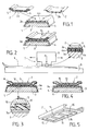
- La figure 1 est une vue en perspective schématique illustrant les différentes phases du procédé d'assemblage suivant l'invention.
- La figure 2 est une vue en élévation schématique d'un appareil de soudage par vibration pouvant être utilisé pour la mise en oeuvre du procédé suivant l'invention, appliqué à l'assemblage d'une glissière sur la surface supérieure d'un ski.
- La figure 3 est une vue en coupe verticale et transversale d'un ski portant, sur sa face supérieure, une glissière assemblée avec le ski après la mise en oeuvre du procédé suivant l'invention.
- La figure 4 est une vue en coupe verticale et transversale d'une variante d'exécution d'une glissière avant son assemblage avec un ski.
- La figure 5 est une vue en perspective de la face inférieure d'une glissière destinée à être assemblée avec un ski.
- La figure 6 est une vue en coupe verticale et transversale d'un ski de fond à arête centrale et d'une pièce rapportée destinée à être assemblée avec le ski, sur son arête centrale.
- La figure 7 est une vue en plan d'un ski adapté pour la mise en oeuvre du procédé d'assemblage suivant l'invention.
- La figure 8 est une vue en coupe verticale et transversale, à plus grande échelle, faite suivant la ligne VIII-VIII de la figure 7.
- La figure 9 est une vue en plan de l'arrière d'un ski comportant un protège-talon rapporté fixé par le procédé suivant l'invention.
- La figure 10 est une vue en coupe verticale et longitudinale faite suivant la ligne X-X de la figure 9.
- La figure 1 illustre schématiquement les diverses opérations conduisant à l'assemblage d'un engin de glisse sur neige 1, en l'occurrence d'un ski, avec une pièce rapportée 2 qui est constituée, dans cet exemple particulier, par une glissière longitudinale d'une fixation de sécurité. Le ski 1 et la glissière 2 sont adaptés, pour permettre la mise en oeuvre du procédé suivant l'invention, de manière à présenter, au moins dans la zone où doit avoir lieu leur liaison, des couches de matière thermofusible venant en contact l'une avec l'autre. A cet effet le ski 1 comporte un noyau 3, constitué d'un matériau couramment utilisé, tel que bois, métal, matière plastique de type polyu- réthane chargée ou non d'une ou plusieurs couches de renfort 3a, généralement métallique en aluminium par exemple ou composé de fibres de verre, carbone, aramide ou autre, imprégnées de matrice thermodurcissable ou thermoplastique. Ce renfort 3a est lui même revêtu d'une couche 4 d'une matière thermofusible. Cette couche 4 peut revêtir la totalité de la face horizontale supérieure du ski 1, en constituant une couche de liaison 4a, et de ses faces latérales inclinées, ou bien uniquement la surface supérieure à l'endroit où doit être montée la glissière 2. De son côté cette glissière 2 peut être réalisée en totalité en matière thermofusible, en présentant alors une face horizontale 2a constituant, par elle-même, une couche de liaison avec le ski 1, comme il est représente dans la partie droite de la figure 1. Elle peut être également constituée par une pièce composite, telle que représentée dans la partie gauche de la figure 1, en comprenant alors un renfort interne 5 en tout matériau approprié, (métal, matière plastique,etc) recouverte d'un revêtement externe 6. La couche horizontale inférieure de ce revêtement 6 forme alors la couche de liaison 2a, en matière thermofusible, intervenant dans le procédé d'assemblage. Cette pièce composite, à renfort 5 et revêtement 6 en matière thermofusible, peut être réalisée par une technique de biinjection, c'est-à-dire d'injections successives dans un moule des deux matières différentes qui adhèrent par soudure ou collage ou encore par coextrusion, lorsqu'il s'agit d'une pièce relativement simple, plane par exemple. Ceci peut être aussi réalisé par surmoulage de l'enveloppe 6, de matière thermofusible autour du renfort 5 en un matériau quelconque. Dans le cas de revêtement appliqué à des pièces métalliques, on peut utiliser une méthode connue par projection électrostatique ou par trempage dans un bain fluidisé par exemple.
- Pour réaliser l'assemblage du ski 1 et de la glissière 2, on place cette glissière, dans la position longitudinale appropriée, sur la face horizontale supérieure du ski 2 de manière que les deux couches de liaison 2a et 4a, en matière thermofusible soient en contact l'une avec l'autre. On applique ensuite, sous pression l'un contre l'autre, le ski 1 et la glissière 2. Dans une forme de mise en oeuvre préférée de l'invention on utilise un appareil de soudage par vibration 7 d'un type connu qui est représenté schématiquement sur la figure 2. Cet appareil de soudage 7 comporte un plateau inférieur fixe 8 et un plateau supérieur mobile 9 qui est soumis à une vibration par des moyens appropriés non représentés. Pour la mise en oeuvre du procédé suivant l'invention en utilisant un tel appareil, on immobilise le ski 1 sur le plateau fixe inférieur 8, en l'alignant dans la direction de la vibration du plateau supérieur mobile 9, et on exerce une pression verticale P, de haut en bas, sur la glissière 2 placée préalablement dans la position longitudinale appropriée sur le ski 1. Ensuite on fait vibrer longitudinalement le plateau mobile supérieur 9 et par conséquent la glissière 2, par rapport au ski inférieur 1 immobilisé, tout en maintenant la pression P. Le mouvement de vibration longitudinal de la glissière 2 sur le ski 1 se traduit par une friction alternative de la couche de matière thermofusible 2a de la glissière mobile 2 sur la couche de matière thermofusible 4a du ski fixe 1. Cette friction alternative provoque un échauffement progressif des deux couches 2a et 4a et la durée de la phase du mouvement de vibration longitudinal de la glissière 2 est choisie suffisante (de l'ordre de quelques secondes) pour que la température atteinte par les deux couches de matière thermofusible 2a et 4a soit supérieure à leur point de fusion. Ces deux couches fondent alors et elles se mélangent intimement, sous l'effet de la pression P, pour ne plus former qu'une couche homogène. Cette pression P est maintenue pendant une courte période de temps, de l'ordre de quelques secondes, après la cessation du mouvement de vibration longitudinal, pour permettre le refroidissement et la solidification de la couche de liaison homogène précédemment en fusion et l'obtention d'une couche rigide et robuste entre le ski 1 et la glissière 2.
- Bien qu'il soit préférable, dans la plupart des cas, de provoquer l'échauffement de la matière thermofusible par une friction alternative dans le sens longitudinal de l'engin de glisse 1, on pourrait aussi obtenir ce résultat en produisant la vibration, engendrant la friction, dans le sens transversal.
- De préférence les couches de matière thermofusible 2a et 4a assurant la liaison entre le ski 1 et la glissière 2 sont en polyamide "11" ou "12" connu sous le nom de "RILSAN". En effet cette matière présente l'avantage de passer rapidement de l'état solide à l'état liquide, pratiquement sans état pâteux intermédiaire, et son point de fusion est précis. Par ailleurs, à l'état liquide, elle flue de façon à combler des creux éventuels et on obtient par conséquent une égalisation des surfaces du ski 1 et de la glissière 2.
- A titre d'exemple on a mis en oeuvre le procédé suivant l'invention avec un ski 1 à revêtement externe en "RILSAN", et avec une glissière 2 à renfort 5 en aluminium recouverte d'un revêtement 6 en "RILSAN". Ce revêtement a été obtenu par un procédé connu de projection électrostatique, l'épaisseur du revêtement 6 de "RILSAN", et notamment de la couche de liaison 2a étant d'environ 150 micromètres. Le revêtement 6 en "RILSAN" peut être aussi obtenu par trempage en bain fluidisé. La pression P exercée pendant la friction alternative a été créée par une force de pression verticale de 800 daN. On a soumis la glissière 2 à un mouvement de vibration dans la direction longitudinale du ski, avec une amplitude ± 0,75 millimètre, avec une fréquence de 240 hertz, pendant une durée de 4 secondes. On a effectué divers essais en supprimant la pression P, immédiatement après la phase du mouvement de vibration longitudinal, ou en la maintenant encore pendant une durée allant jusqu'à 5 secondes après la cessation du mouvement de vibration. Avec ce procédé on a obtenu une résistance à l'arrachement, dans le sens vertical, entre le ski 1 et la glissière 2 de l'ordre de grandeur de celle obtenue avec un assemblage au moyen de vis.
- La face de la pièce rapportée 2 qui vient en contact avec le ski 1, peut être adaptée de manière à renforcer l'adhérence. Par exemple, ainsi qu'il est représenté sur la figure 3, la surface inférieure de la glissière 2 présente des rainures longitudinales (et/ou transversales) 10 à section droite en forme de queue d'aronde. De ce fait, lors de la friction alternative, la matière thermofusible des deux couches de liaison 2a et 4a pénètre, après sa fusion et sous l'effet de la pression, a l'intérieur des rainures 11, ce qui permet de résorber la matière en excès en fusion et d'améliorer l'accrochage de la glissière 2 sur le ski 1 par un ancrage mécanique résultant des plots d'accrochage 11 constitués par la matière ayant flué et durci dans les rainures 10.
- Suivant une variante, la surface inférieure de la glissière 2 peut présenter des nervures en saillie, comme il est représenté sur les figures 4 et 5. Sur la figure 4 la face inférieure de la glissière 2 présente des nervures longitudinales (et/ou transversales) 12 délimitant entre elles des creux 13. De ce fait le contact, la friction et la soudure sont concentrés à l'endroit des nervures 12 et la matière thermofusible en excès peut fluer dans les creux 13 situés entre les nervures 12.
- La figure 5 illustre une variante d'exécution dans laquelle la face inférieure de la glissière 2 présente deux nervures longitudinales 14, proches des bords longitudinaux de la glissière 2, et qui sont reliées par des nervures transversales 15, en délimitant entre elles des creux 16 dans lesquels peut fluer la matière thermofusible en fusion. Les nervures peuvent aussi être présentes à la surface supérieure du ski.
- La figure 6 illustre une application du procédé suivant l'invention à un ski de fond 17, comportant un noyau interne revêtu d'une enveloppe externe 18 constitué d'une couche de matière thermofusible telle que le "RILSAN". Le ski de fond 17 présente, à sa partie supérieure, une arête longitudinale centrale 19, destinée à être coiffée par une pièce rapportée 20 constituant une plaque d'appui pour une chaussure de ski de fond. Cette plaque d'appui 20 est constituée en totalité, en "RILSAN", comme il est représenté sur la figure 6, ou bien encore elle est formée par une pièce composite à revêtement externe en "RILSAN". L'arête 19 du ski de fond 17 présente une section transversale trapézoïdale, à faces latérales inclinées 19a convergeant vers le haut, et de la même façon la plaque d'appui rapportée 20 a une section transversale verticale en forme de U ou de C ouvert vers le bas. Les deux branches latérales 20a de la plaque d'appui rapportée 20, qui s'étendent vers le bas, sont verticales ou légèrement convergentes vers le haut. Ces deux branches 20a sont inclinées l'une par rapport à l'autre d'un angle qui est inférieur à l'angle dont sont inclinées l'une par rapport à l'autre, les deux faces latérales 19a de l'arête 19. Comme dans l'exemple décrit précédemment, lors de la mise en oeuvre du procédé d'assemblage, la plaque rapportée supérieure 20 est appliquée sous pression sur l'arête 19 si bien que ses branches latérales inférieures 20a sont écartées vers l'extérieur, du fait de leur inclinaison relative différente de celle des faces latérales inclinées 19a de l'arête 19, si bien qu'elles sont ainsi fortement pressées contre ces dernières faces 19a. Pour assurer l'assemblage du ski 17 et de la plaque d'appui rapportée 20, on a exercé, pour produire la pression de contact, une force verticale de 600 daN, l'amplitude du mouvement de vibration longitudinal a été de + 0,6 millimètre et la durée du mouvement de vibration a été de 3 à 4 secondes.
- On peut utiliser, pour la mise en oeuvre du procédé suivant l'invention, des couches de matière thermofusible qui sont ou non chargées. Par exemple la glissière rapportée 2 peut être réalisée en "RILSAN" chargé de fibres. Dans ce cas on peut utiliser, pour la glissière rapportée 2, un pourcentage de fibres (par exemple 15%) inférieur à celui (35%) ou plus qui est couramment utilisé pour la fabrication de glissières assemblées avec un ski au moyen de vis. Cette réduction notable du pourcentage des fibres permet, au moment de l'opération de soudage par friction alternative, une meilleure pénétration du "RILSAN" fondu entre les fibres et un excellent accrochage de la glissière 2 sur le ski 1. On obtient également ainsi une amélioration de la souplesse de la glissière, grâce à l'abaissement de la proportion de fibres, et par conséquent une diminution des contraintes entre la glissière 2 et le ski 1, notamment dans les mouvements de flexion du ski. En effet, dans le cas d'une glissière 2 maintenue pardesvis, toute sollicitation apparaissant entre la glissière 2 et le ski 1 converge vers les différentes vis de fixation. Au contraire dans le cas d'une glissière fixée par soudage, les sollicitations se répartissent sur l'ensemble de la surface de contact entre la glissière 2 et le ski 1.
- La figure 7 représente une variante selon laquelle la décoration du ski est portée par une couche de matériau 21 qui n'est pas compatible avec la soudure par vibration. Dans le mode de réalisation illustré, la couche de matériau 21 est présente à l'avant du ski, à l'arrière du ski, mais pas dans la zone centrale la du patin du ski. Dans cette zone la, le renfort 3a du ski est directement accessible. Avantageusement, ce renfort est en matériau compatible avec la glissière 2, pour une soudure par vibration. Il est donc possible d'appliquer et souder par vibration la glissière 2 sur le renfort 3a. Cette variante est aussi applicable au cas où le renfort 3a est accessible directement d'un bout à l'autre du ski.
- La figure 8 représente un ski 1 dont le revêtement 21, approprié pour la décoration du ski, n'est pas réalisé en une matière compatible convenant pour le soudage par vibration. Dans ce cas, on forme le revêtement non compatible 21 de manière qu'il soit très fin dans la zone où doit s effectuer l'assemblage de la pièce rapportée 2, c'est-à-dire la zone du patin du ski dans le cas de la fixation d'une glissière 2, et qu'il se présente, à cet endroit, sous la forme d'une mince pellicule 21a. Sous cette pellicule 21a se trouve un insert 22 qui est réalisé en toute matière compatible avec la pièce rapportée 2 assemblée par soudage par vibration. Dans ce cas la première partie de la phase de friction de la pièce rapportée 2 sur le ski a pour effet de détruire, au moins localement, la pellicule superficielle 21a, de telle façon que l'insert en matériau compatible 22 soit ensuite accessible. Il est particulièrement avantageux que la pièce rapportée 2 (ou le ski 1) présente des nervures en saillie 12, comme il est représenté par exemple sur les figures 4 et 5, afin de concentrer localement la friction et de permettre l'écoulement du matériau non compatible de la pellicule 21a dans les creux 13 délimités par les nervures.
- Bien entendu, l'invention ne se limite pas aux modes de réalisation présentés à titre d'exemple, ainsi on peut imaginer le cas où les couches renforts 3a formant la structure de l'engin de glisse ont une matrice thermoplastique chargée, compatible avec une pièce à rapporter. Dans ce cas on peut se dispenser de la couche 4 thermofusible. La pièce rapportée est directement appliquée et soudée par friction sur le renfort 3a.
- Les figures 9 et 10 illustrent une autre variante de l'invention selon laquelle la pièce rapportée est un protège-talon, c'est-à-dire un élément que le ski présente à l'endroit de son talon dans le but de le protéger des chocs sur le sol. Le protège-talon présente une partie principale 23, qui se prolonge par un tenon 24, lequel tenon est destiné à s'engager dans un logement 25 formé dans la face frontale postérieure du ski et qui est de forme et de section correspondantes à celles du tenon 24. Les surfaces interne du logement 25 et externe du tenon 24 sont compatibles entre elles pour une soudure par vibration.
- Avantageusement, ainsi que représenté sur la figure 10, le tenon 24 et le logmenet 25 sont vus en coupe par des plans longitudinal et vertical sensiblement biseautés. En outre, de préférence, le biseau du logement 25 présente, dans ces plans longitudinal et vertical, des dimensions légèrement inférieures à celles du tenon 24, de telle façon qu'une force exercée sur le protège-talon, dans le sens longitudinal, provoque un coincement du tenon 24 dans son logement 25. Par ailleurs, la largeur du tenon 24 est sensiblement inférieure à la largeur de son logement 25, ainsi que cela est visible sur la figure 9.
- Le procédé présente les phases suivantes : le tenon 24 du protège-talon est engagé dans le logement 25, et animé d'un mouvement de translation vibratoire par rapport au ski. Ce mouvement est orienté dans une direction horizontale et transversale. Une force de pression applique le protège-talon contre le ski dans une direction longitudinale. Après une durée déterminée suffisante pour mettre les surfaces de contact en fusion, la vibration est arrêtée, le protège-talon est alors maintenu avec pression contre l'arrière du ski dans sa position définitive. On peut aussi orienter les vibrations entre le talon du ski et le protège-talon selon une direction horizontale et longitudinale.
Claims (22)
Priority Applications (1)
| Application Number | Priority Date | Filing Date | Title |
|---|---|---|---|
| AT91101395T ATE95715T1 (de) | 1990-03-26 | 1991-02-02 | Verfahren zur herstellung eines skiaehnlichen sportgeraets und einer laengsfuehrungsvorrichtung und zusammenbau eines sportgeraets und einer laengsfuehrungsvorrichtung. |
Applications Claiming Priority (2)
| Application Number | Priority Date | Filing Date | Title |
|---|---|---|---|
| FR9003824 | 1990-03-26 | ||
| FR9003824A FR2659865B1 (fr) | 1990-03-26 | 1990-03-26 | Procede d'assemblage d'une piece rapportee et d'un engin de glisse sur neige, et engin et piece rapportee adaptes pour la mise en óoeuvre de ce procede. |
Publications (3)
| Publication Number | Publication Date |
|---|---|
| EP0448936A1 EP0448936A1 (fr) | 1991-10-02 |
| EP0448936B1 true EP0448936B1 (fr) | 1993-10-13 |
| EP0448936B2 EP0448936B2 (fr) | 1998-11-25 |
Family
ID=9395106
Family Applications (1)
| Application Number | Title | Priority Date | Filing Date |
|---|---|---|---|
| EP19910101395 Expired - Lifetime EP0448936B2 (fr) | 1990-03-26 | 1991-02-02 | Procédé d'assemblage d'une pièce rapportée et d'un engin de glisse sur neige et ensemble constitué par un engin de glisse et une pièce rapporteé |
Country Status (6)
| Country | Link |
|---|---|
| US (1) | US5338051A (fr) |
| EP (1) | EP0448936B2 (fr) |
| JP (1) | JPH0768000A (fr) |
| AT (1) | ATE95715T1 (fr) |
| DE (1) | DE69100491T3 (fr) |
| FR (1) | FR2659865B1 (fr) |
Families Citing this family (30)
| Publication number | Priority date | Publication date | Assignee | Title |
|---|---|---|---|---|
| US5449192A (en) * | 1990-09-12 | 1995-09-12 | Salomon S. A. | Boot support plate for ski binding |
| AT407712B (de) * | 1995-08-14 | 2001-05-25 | Atomic Austria Gmbh | Brettartiges gleitgerät, insbesondere schi mit einem tragkörper |
| FR2740692B1 (fr) * | 1995-11-03 | 1998-01-23 | Skis Lacroix & Co Sa | Ski en forme de section non rectangulaire |
| US6293577B1 (en) | 1996-10-03 | 2001-09-25 | Peter Shields | Foot binding assembly |
| AU4776597A (en) * | 1996-11-29 | 1998-06-22 | Norsk Hydro Asa | Process for connecting two objects |
| US6029991A (en) * | 1997-03-13 | 2000-02-29 | Frey; Bernard M. | Impact releasable snowboard boot binding assembly and method |
| FR2775437B1 (fr) | 1998-02-27 | 2000-05-19 | Salomon Sa | Dispositif interface entre un ski et des elements de retenue d'une chaussure sur le ski |
| US6309586B1 (en) * | 1999-06-15 | 2001-10-30 | Jumbo Snowboards, Llc | Use of co-injection molding to produce composite parts including a molded snowboard with metal edges |
| WO2001028757A1 (fr) * | 1999-10-20 | 2001-04-26 | Siemens Canada Limited | Geometrie differentielle de cordon de soudure |
| FR2801801B1 (fr) | 1999-12-06 | 2003-12-19 | Salomon Sa | Dispositif amortisseur des vibrations d'un ski, et ski equipe d'un tel dispositif |
| FR2803533B1 (fr) * | 2000-01-07 | 2002-04-05 | Look Fixations Sa | Dispositif d'appui pour l'avant d'une chaussure de ski sur un ski |
| FR2805172B1 (fr) | 2000-02-22 | 2002-05-03 | Rossignol Sa | Element interface utilise sur une planche de surf |
| EP1240925A1 (fr) * | 2001-03-12 | 2002-09-18 | Andreas Allmann | Glissière et dispositif pour la connexion d'une fixation pour chaussure de sport à un ski ou à une planche de surf |
| DE10254471A1 (de) | 2002-11-21 | 2004-06-03 | Madsus A/S | Ski mit Bindungs-Montagehilfe, Verfahren zur Herstellung eines solchen Ski sowie entsprechende Montagehilfe |
| DE202004001356U1 (de) * | 2004-01-29 | 2005-04-14 | Blizzard Sport Ges.M.B.H. | Ski, insbesondere Alpinski |
| DE202004004304U1 (de) * | 2004-03-18 | 2004-05-13 | Tyrolia Technology Gmbh | Gleitbrett, insbesondere Ski |
| FR2873592B1 (fr) | 2004-07-30 | 2006-12-01 | Salomon Sa | Ensemble de retenue d'une chaussure sur une planche de glisse |
| FR2879939B1 (fr) * | 2004-12-29 | 2007-03-16 | Salomon Sa | Procede de fabrication d'une planche de glisse ou de roulage a structure composite |
| ATE426439T1 (de) | 2005-01-10 | 2009-04-15 | Rottefella As | Ski oder dergleichen schneegleitgerat mit bindungs-montagehilfe |
| FR2884432B1 (fr) * | 2005-04-15 | 2010-01-01 | Salomon Sa | Dispositif interface entre une planche de glisse et un element de retenue d'une chaussure |
| FR2887155A1 (fr) * | 2005-06-20 | 2006-12-22 | Skis Rossignol Sa Sa | Perfectionnement pour planche de glisse sur neige |
| DE102005054502A1 (de) * | 2005-11-16 | 2007-05-24 | Conti Temic Microelectronic Gmbh | Verfahren zum Verbinden zweier Werkstücke |
| WO2007067928A2 (fr) * | 2005-12-06 | 2007-06-14 | K-2 Corporation | Système de fixation de ski |
| EP2123333B1 (fr) * | 2008-05-19 | 2015-09-02 | Rottefella AS | Plaque de fixation avec articulation |
| DE102010003645A1 (de) * | 2010-04-06 | 2011-10-06 | Robert Bosch Gmbh | Wischblatt für einen Scheibenwischer |
| US9526971B1 (en) | 2015-09-18 | 2016-12-27 | Rossland Binding Company | Remote release ski binding |
| CZ306883B6 (cs) * | 2016-04-25 | 2017-08-23 | SPORTEN, a.s. | Skokanská lyže s upravenou vnitřní výztuhou |
| US10729968B2 (en) | 2018-05-25 | 2020-08-04 | Rossland Binding Company | Remote release snowboard binding |
| CN108905174A (zh) * | 2018-08-21 | 2018-11-30 | 华北理工大学 | 一种可调速转向滑雪板与滑雪靴 |
| CN120902285A (zh) * | 2024-04-30 | 2025-11-07 | 明门(中国)幼童用品有限公司 | 一种摩擦焊接结构 |
Family Cites Families (23)
| Publication number | Priority date | Publication date | Assignee | Title |
|---|---|---|---|---|
| FR1282053A (fr) * | 1960-12-06 | 1962-01-19 | Skis composites | |
| US3458380A (en) * | 1965-08-26 | 1969-07-29 | Union Carbide Corp | Method of bonding thermoplastics |
| AT313136B (de) * | 1971-07-07 | 1974-02-11 | Christine Nowak | Zur Aufnahme der Laufkanten sowie des Sohlenbelages dienender Skibauteil aus thermoplastischem Material |
| FR2208692B1 (fr) * | 1972-12-01 | 1976-08-20 | Salomon Georges P J | |
| US3977688A (en) * | 1972-12-30 | 1976-08-31 | Nippon Gakki Seizo Kabushiki Kaisha | Structure for connecting a ski binding clamp to a ski |
| CA983543A (en) * | 1972-12-30 | 1976-02-10 | Katsuhiko Imagawa | Connecting structure for ski binding clamp to ski board |
| US4058421A (en) * | 1976-10-07 | 1977-11-15 | Branson Ultrasonics Corporation | Method of joining non-fusible workpieces using frictional energy |
| US4118051A (en) * | 1976-12-17 | 1978-10-03 | Nissei Plastics Industrial Co., Ltd. | Injection molded ski and method for producing the same |
| US4377428A (en) * | 1981-06-15 | 1983-03-22 | Branson Ultrasonics Corporation | Method of friction welding |
| FR2596286B1 (fr) * | 1986-03-26 | 1989-10-06 | Rossignol Sa | Ski a decor protege |
| AT389451B (de) * | 1986-11-07 | 1989-12-11 | Isosport Verbundbauteile | Verfahren zur herstellung eines ein duromeres kunstharz enthaltenden skibauteiles und skibauteil hergestellt nach diesem verfahren |
| FR2610525A1 (fr) * | 1987-02-05 | 1988-08-12 | Salomon Sa | Ski de fond presentant une nervure longitudinale en saillie par rapport a sa face superieure |
| ATA42087A (de) * | 1987-02-26 | 1991-09-15 | Isovolta | Verfahren zur skiherstellung |
| FR2620628B2 (fr) * | 1987-02-27 | 1994-08-19 | Salomon Sa | Procede pour realiser un ski et ski fait selon ce procede |
| FR2615406B1 (fr) * | 1987-05-22 | 1989-07-21 | Salomon Sa | Ski a amortissement reparti |
| FR2620974B1 (fr) * | 1987-09-25 | 1991-09-27 | Salomon Sa | Procede de decoration d'articles par une methode d'impression par sublimation |
| US4953885A (en) * | 1987-10-21 | 1990-09-04 | Norton Company | Ski construction |
| FR2627700B1 (fr) * | 1988-02-25 | 1991-05-03 | Salomon Sa | Procede d'assemblage d'un ski par soudage, et structure de ski ainsi obtenue |
| AT390198B (de) * | 1988-02-26 | 1990-03-26 | Danutec Werkstoff | Verfahren zur herstellung eines schis und schi hergestellt nach diesem verfahren |
| FR2629352B1 (fr) * | 1988-03-29 | 1990-12-28 | Salomon Sa | Procede pour realiser un ski, et ski realise selon ce procede |
| DE3818569C1 (fr) * | 1988-06-01 | 1989-04-06 | Gurit-Essex Ag, Freienbach, Ch | |
| GB8829993D0 (en) * | 1988-12-22 | 1989-02-15 | Westland Helicopters | Method for forming components from fibre-reinforced thermoplastic materials |
| FR2654644B1 (fr) * | 1989-11-22 | 1992-03-13 | Salomon Sa | Procede de fabrication d'un ski injecte, et structure de ski obtenue par ce procede. |
-
1990
- 1990-03-26 FR FR9003824A patent/FR2659865B1/fr not_active Expired - Fee Related
-
1991
- 1991-02-02 AT AT91101395T patent/ATE95715T1/de not_active IP Right Cessation
- 1991-02-02 EP EP19910101395 patent/EP0448936B2/fr not_active Expired - Lifetime
- 1991-02-02 DE DE69100491T patent/DE69100491T3/de not_active Expired - Fee Related
- 1991-03-26 JP JP6064891A patent/JPH0768000A/ja active Pending
-
1993
- 1993-01-22 US US08/007,650 patent/US5338051A/en not_active Expired - Fee Related
Also Published As
| Publication number | Publication date |
|---|---|
| DE69100491D1 (de) | 1993-11-18 |
| US5338051A (en) | 1994-08-16 |
| DE69100491T2 (de) | 1994-05-11 |
| EP0448936A1 (fr) | 1991-10-02 |
| EP0448936B2 (fr) | 1998-11-25 |
| JPH0768000A (ja) | 1995-03-14 |
| ATE95715T1 (de) | 1993-10-15 |
| FR2659865A1 (fr) | 1991-09-27 |
| FR2659865B1 (fr) | 1992-07-24 |
| DE69100491T3 (de) | 1999-06-24 |
Similar Documents
| Publication | Publication Date | Title |
|---|---|---|
| EP0448936B1 (fr) | Procédé d'assemblage d'une pièce rapportée et d'un engin de glisse sur neige et ensemble constitué par un engin de glisse et une pièce rapporteé | |
| EP0577947B1 (fr) | Ski nervuré muni d'un support | |
| EP0543743B2 (fr) | Ski en forme de section non rectangulaire | |
| EP1000641A1 (fr) | Engin de glisse comprenant un dispositif d'interface de fixations relié à un ski | |
| FR2669547A1 (fr) | Ski presentant un cote superieur profile en relief. | |
| FR2775437A1 (fr) | Dispositif interface entre un ski et des elements de retenue d'une chaussure sur le ski | |
| EP1842442A1 (fr) | Semelle de chaussure de ski de fond comportant des moyens perfectionnes d'ancrage d'un moyen de liaison et chaussure munie d'une telle semelle | |
| FR2798969A1 (fr) | Dispositif de verrouillage d'une position d'une piece mobile par rapport a une piece fixe | |
| FR2532529A1 (fr) | Chaussure de ski de fond | |
| CA2200417A1 (fr) | Planche de ski entouree d'une carre continue | |
| CA2007121A1 (fr) | Procede de montage rapide d'un dispositif de fixation d'une chaussure a un ski, et notamment d'un dispositif de fixation pour ski de fond, ski et dispositif de fixation pour la mise en oeuvre d'un tel procede de montage | |
| EP2082788A1 (fr) | Ski alpin avec moyens de réglage | |
| CA3181925A1 (fr) | Dispositif de jonction de bande transporteuse a cables muni d'elements de blocage de cable | |
| EP3231489B1 (fr) | Planche de glisse, dispositif de fixation de chaussure destiné à équiper une telle planche et équipement de snowboard comprenant ladite planche et ledit dispositif de fixation | |
| FR2855066A1 (fr) | Planche de glisse sur neige avec un ensemble exterieur de decoration et de protection et procede de fabrication | |
| FR2715860A1 (fr) | Dispositif d'amortissement pour des éléments d'accouplement, par exemple une fixation de chaussures de ski utilisant un tel dispositif d'amortissement et procédé pour fabriquer un tel dispositif. | |
| EP0677306B1 (fr) | Ski et son procédé de fabrication | |
| EP1258420A1 (fr) | Garde-boue en matière plastique | |
| FR2986436A1 (fr) | Planche de glisse sur neige | |
| EP1844821A1 (fr) | Procédé de fabrication d'un engin de glisse et engin de glisse obtenu par ce procédé | |
| EP3632513B1 (fr) | Planche de glisse a noyau injecte equipe d'elements de renfort longitudinaux | |
| FR2659243A1 (fr) | Perfectionnements apportes aux skis. | |
| FR2763861A1 (fr) | Plateforme en une seule partie pour le montage sur un ski alpin, d'une fixation pour chaussure | |
| FR2804612A1 (fr) | Procede de realisation d'une planche de glisse sur neige a extremite en etrave | |
| FR3010323A1 (fr) | Planche de glisse et son procede de fabrication |
Legal Events
| Date | Code | Title | Description |
|---|---|---|---|
| PUAI | Public reference made under article 153(3) epc to a published international application that has entered the european phase |
Free format text: ORIGINAL CODE: 0009012 |
|
| AK | Designated contracting states |
Kind code of ref document: A1 Designated state(s): AT DE IT |
|
| 17P | Request for examination filed |
Effective date: 19910916 |
|
| 17Q | First examination report despatched |
Effective date: 19920311 |
|
| GRAA | (expected) grant |
Free format text: ORIGINAL CODE: 0009210 |
|
| ITF | It: translation for a ep patent filed | ||
| AK | Designated contracting states |
Kind code of ref document: B1 Designated state(s): AT DE IT |
|
| REF | Corresponds to: |
Ref document number: 95715 Country of ref document: AT Date of ref document: 19931015 Kind code of ref document: T |
|
| REF | Corresponds to: |
Ref document number: 69100491 Country of ref document: DE Date of ref document: 19931118 |
|
| PLBI | Opposition filed |
Free format text: ORIGINAL CODE: 0009260 |
|
| PLAB | Opposition data, opponent's data or that of the opponent's representative modified |
Free format text: ORIGINAL CODE: 0009299OPPO |
|
| 26 | Opposition filed |
Opponent name: HTM SPORT- UND FREIZEITGERAETE GMBH Effective date: 19940712 |
|
| R26 | Opposition filed (corrected) |
Opponent name: HTM SPORT- UND FREIZEITGERAETE AKTIENGESELLSCHAFT Effective date: 19940712 |
|
| PLAW | Interlocutory decision in opposition |
Free format text: ORIGINAL CODE: EPIDOS IDOP |
|
| PLAW | Interlocutory decision in opposition |
Free format text: ORIGINAL CODE: EPIDOS IDOP |
|
| PLBQ | Unpublished change to opponent data |
Free format text: ORIGINAL CODE: EPIDOS OPPO |
|
| PLAB | Opposition data, opponent's data or that of the opponent's representative modified |
Free format text: ORIGINAL CODE: 0009299OPPO |
|
| R26 | Opposition filed (corrected) |
Opponent name: HTM SPORT- UND FREIZEITGERAETE AKTIENGESELLSCHAFT Effective date: 19940712 |
|
| PLAW | Interlocutory decision in opposition |
Free format text: ORIGINAL CODE: EPIDOS IDOP |
|
| PUAH | Patent maintained in amended form |
Free format text: ORIGINAL CODE: 0009272 |
|
| STAA | Information on the status of an ep patent application or granted ep patent |
Free format text: STATUS: PATENT MAINTAINED AS AMENDED |
|
| 27A | Patent maintained in amended form |
Effective date: 19981125 |
|
| AK | Designated contracting states |
Kind code of ref document: B2 Designated state(s): AT DE IT |
|
| PG25 | Lapsed in a contracting state [announced via postgrant information from national office to epo] |
Ref country code: IT Free format text: LAPSE BECAUSE OF NON-PAYMENT OF DUE FEES Effective date: 20050202 |
|
| PGFP | Annual fee paid to national office [announced via postgrant information from national office to epo] |
Ref country code: DE Payment date: 20060126 Year of fee payment: 16 |
|
| PGFP | Annual fee paid to national office [announced via postgrant information from national office to epo] |
Ref country code: AT Payment date: 20060213 Year of fee payment: 16 |
|
| PG25 | Lapsed in a contracting state [announced via postgrant information from national office to epo] |
Ref country code: AT Free format text: LAPSE BECAUSE OF NON-PAYMENT OF DUE FEES Effective date: 20070202 |
|
| PG25 | Lapsed in a contracting state [announced via postgrant information from national office to epo] |
Ref country code: DE Free format text: LAPSE BECAUSE OF NON-PAYMENT OF DUE FEES Effective date: 20070901 |