EP0448966A1 - Dispositif, en particulier pour prendre des bains ou bains de siège - Google Patents
Dispositif, en particulier pour prendre des bains ou bains de siège Download PDFInfo
- Publication number
- EP0448966A1 EP0448966A1 EP91102755A EP91102755A EP0448966A1 EP 0448966 A1 EP0448966 A1 EP 0448966A1 EP 91102755 A EP91102755 A EP 91102755A EP 91102755 A EP91102755 A EP 91102755A EP 0448966 A1 EP0448966 A1 EP 0448966A1
- Authority
- EP
- European Patent Office
- Prior art keywords
- chamber
- layer
- filling
- shape
- tub
- Prior art date
- Legal status (The legal status is an assumption and is not a legal conclusion. Google has not performed a legal analysis and makes no representation as to the accuracy of the status listed.)
- Granted
Links
Images


Classifications
-
- A—HUMAN NECESSITIES
- A47—FURNITURE; DOMESTIC ARTICLES OR APPLIANCES; COFFEE MILLS; SPICE MILLS; SUCTION CLEANERS IN GENERAL
- A47K—SANITARY EQUIPMENT; ACCESSORIES THEREFOR, e.g. TOILET ACCESSORIES
- A47K3/00—Baths; Showers; Appurtenances therefor
- A47K3/001—Accessories for baths, not provided for in other subgroups of group A47K3/00; Insertions, e.g. for babies; Tubs suspended or inserted in baths; Security or alarm devices; Protecting linings or coverings; Devices for cleaning or disinfecting baths; Bath insulation
-
- A—HUMAN NECESSITIES
- A61—MEDICAL OR VETERINARY SCIENCE; HYGIENE
- A61H—PHYSICAL THERAPY APPARATUS, e.g. DEVICES FOR LOCATING OR STIMULATING REFLEX POINTS IN THE BODY; ARTIFICIAL RESPIRATION; MASSAGE; BATHING DEVICES FOR SPECIAL THERAPEUTIC OR HYGIENIC PURPOSES OR SPECIFIC PARTS OF THE BODY
- A61H9/00—Pneumatic or hydraulic massage
- A61H9/0021—Hydraulic massage
-
- A—HUMAN NECESSITIES
- A61—MEDICAL OR VETERINARY SCIENCE; HYGIENE
- A61H—PHYSICAL THERAPY APPARATUS, e.g. DEVICES FOR LOCATING OR STIMULATING REFLEX POINTS IN THE BODY; ARTIFICIAL RESPIRATION; MASSAGE; BATHING DEVICES FOR SPECIAL THERAPEUTIC OR HYGIENIC PURPOSES OR SPECIFIC PARTS OF THE BODY
- A61H33/00—Bathing devices for special therapeutic or hygienic purposes
- A61H2033/0004—Bathing devices specially adapted for treating burned patients
-
- A—HUMAN NECESSITIES
- A61—MEDICAL OR VETERINARY SCIENCE; HYGIENE
- A61H—PHYSICAL THERAPY APPARATUS, e.g. DEVICES FOR LOCATING OR STIMULATING REFLEX POINTS IN THE BODY; ARTIFICIAL RESPIRATION; MASSAGE; BATHING DEVICES FOR SPECIAL THERAPEUTIC OR HYGIENIC PURPOSES OR SPECIFIC PARTS OF THE BODY
- A61H2201/00—Characteristics of apparatus not provided for in the preceding codes
- A61H2201/16—Physical interface with patient
- A61H2201/1602—Physical interface with patient kind of interface, e.g. head rest, knee support or lumbar support
- A61H2201/1654—Layer between the skin and massage elements, e.g. fluid or ball
Definitions
- the invention relates to a device, in particular for administering full or hip baths, and to a method for operating such a device and its use according to the preamble of claims 1, 29 and 30, respectively.
- the bath medium cools prematurely. This is particularly important for body-shaped tubs, because this appearance also affects the sides. In particular, so-called “overheating baths” are then practically no longer feasible because the bath medium representing a heat medium and heat reservoir is too small on many parts of the body, especially in the lumbar and buttocks area.
- a tub interior that is too small in size can also be perceived as a disadvantage in the case of tall and overweight people, which in some cases can even cause anxiety. It is easy to imagine that the anxiety states mentioned can occur in these cases, especially when it is considered that the bathing temperatures can also be up to 42 ° C, for example, and that the correspondingly shaped, previously known tubs allow deep immersion, so that in Abdominal and chest areas become more noticeable due to the pressure exerted by the medium.
- Another disadvantage is that there is no longer enough bath medium available between the tub surface and the body.
- a generic device for administering full or seated peloid baths according to DE 30 46 628 C2 and EP 18 390 B1 has already become known, in which a film upper and a film subspace can be separated by means of a film.
- This device is suitable for patients of various sizes and weights.
- the portion of bath fluid that comes into contact with the patient's body and is lost through pouring away after the end of therapy covers only a small fraction of the total volume of peloid bath liquid contained in the tub, since the peloid bath liquid located below the separating film and also serving as a heating medium continues to exist remains in the tub and can also be used for other patients and bathers.
- the device is also intended to provide an improvement for persons of above-average size or weight, or above-average size of small and light persons.
- a thermal bath especially with a convective heat transfer, should also be possible.
- a tub sub-space can be formed which can be filled with a heating medium.
- there is at least one convection-inhibiting layer or one convection-inhibiting chamber which is at least partially filled and which, even in the case of aqueous solutions, enables an at least largely conductive heat transfer also in the direction of the bathtub partition into the actual bath room.
- pulpy media such as, for example, bog or peloid as a heat reservoir.
- granular or particulate materials are used for this purpose, which are preferably buoyant.
- these particle-shaped to granular filling elements rest against the dividing wall of the body wall from below and largely prevent heat convection and thus only enable heat conduction.
- the bathing medium can otherwise be heated up by a heating and circulating process between two bathing cycles. Since, moreover, these, in particular, particulate to granular filling elements are interchangeable, largely convective heat transfer can also be achieved at any time with the device according to the invention.
- the partition is formed from a separating film in a manner known per se. Because here too, the proportion of bathing liquid that comes into contact with a patient's body is comparatively low and thus helps to reduce costs.
- the film naturally offers an optimal adaptation to different ones Body sizes and body weights, which offers additional advantages to a bathtub comprising a fixed tub wall, in particular a shaped body tub. At the same time, however, this additionally prevents a patient from getting tangled with the legs in the separating film, for example.
- the release film does not fit closely to the body due to the medium pressure in the film subspace and, depending on the depth of sinking in and the size of the patient, virtually completely wraps and encloses it.
- the device according to the invention has a shape adaptation chamber in a preferred embodiment.
- This is filled with a moldable medium, which is also z. B. has particle or granular form.
- this adaptable chamber can now be optimally adapted to the body shape of the patient or bathers via the separating film, since the particle or granule-like filling yields accordingly in the adaptable chamber.
- the pressure can then be reduced in the adaptable chamber in relation to the ambient pressure.
- the particle- or granulate-like filling virtually solidifies and compresses, with the result that the shape that is optimally adapted to the body shape is fixed and retained as a lying surface.
- the distance between the release film and the body is also increased, so that a sufficient distance of at least a few centimeters, usually at least 4 cm, is formed between the top of the film and the patient's body, via which sufficient bathing liquid penetrate directly to the body can.
- the particle- or granulate-like filling also serves as a heat storage medium, which can be heated to a desired level between the individual treatment phases or can be kept at a certain temperature or heated to this during the bathing process.
- a gaseous, liquid and / or slurry-like medium can flow through the intermediate spaces formed with the particle- or granule-like filling even above all even at reduced pressure.
- a conductive heat transfer from the lower filling into the bathing liquid above the separating film but also a convective heat transfer via the film into the bathing medium.
- even parts of the body could be spared from such a heat transfer, for example by inserting an insulating intermediate layer in the separating film above or below or between the separating film and the shape-adapting chamber.
- An improvement of the effect according to the invention can also be achieved by additionally providing at least one compensation chamber.
- This is preferably provided below the adaptable chamber in the tub. It can be filled with a suitable medium, such as gas, air or water, and is used for height compensation according to the size and body weight of a bather. This also makes it easier to get in and out of the tub.
- At least one compensation chamber can be expanded to such an extent that the bath liquid of the bulged separating film can be emptied.
- the head shell itself may have little or no conformability. If the drain for the bathing liquid is provided there, problem-free emptying is possible after completion of the bath.
- the device comprises a trough 1, on which a separating film 3 can be provided or anchored in a suitable manner to form a film upper chamber 5 and a film lower chamber 7 separated therefrom.
- the separating film extends beyond the upper circumferential edge of the tub and is interchangeably fastened there, for example via a sealing frame 9.
- the separating film 3 can, for example, consist of very elastic material, a material film, rubber or other elastomeric materials and can be clamped to the tub in a suitable manner.
- Layer or chamber 11 which is filled with a particulate or granular or similar material which is at least slightly flexible, evasive and / or body-adaptable under the pressure load of a bather.
- a particulate or granular or similar material which is at least slightly flexible, evasive and / or body-adaptable under the pressure load of a bather.
- All conceivable materials come into consideration here, which, for example, can also have a spherical shape and are in themselves not flexible and elastic. The adaptability is ensured at least by the evasive movement of the granular or spherical particles.
- this granular to particulate filling 13 is provided directly in the trough below the separating film 3.
- one or more compensation chambers 15 can be provided. In the exemplary embodiment shown, these can be individually adjusted so that a desired optimal lying area can be achieved for a bather, as is shown, for example, in FIG.
- three compensation chambers 15 are provided at least in the longitudinal direction, a compensation chamber for increased support of the foot region extending approximately into the knee region, to which a lower compensation chamber 15 for supporting the buttocks to the back region, possibly in the shoulder region, is connected , and that a comparatively high compensation chamber 15 is provided for the support of the head region.
- compensation chambers 15 are elastic and can, for. B. but pressure lines 16 are deflated or inflated or expanded separately so that an optimal altitude and adaptation to the size and weight of a patient is achieved.
- all compensation chambers 15 can also be expanded in such a way that problem-free boarding and alighting is possible, in which the shape-adaptable layer or chamber 11 with the elastic film as required practically, for example, can be raised almost to the upper edge of the tub 1. After the corresponding lying down, conversely, a lowering into the desired bathing position can then take place again by releasing the pressure medium in the compensation chambers 15.
- the compensation chambers 15 can also be filled up beyond the upper tub edge. This serves to drain the bath medium.
- a non-inflatable, possibly rather rigid or stiffened, i.e. H. fixed head shell 17 may be provided, which remains more or less in its position shown in FIG. 1 even when the separating film 3 is otherwise lifted up beyond the rim of the tub. If there is an outlet line 19 at the lowest point of the head shell 17, which is otherwise closed during the bathing process by a valve (not shown in any more detail), the bathing water can run off easily via the head shell 17 and the subsequent outlet line 19. The raised release film protruding upwards can be rinsed off, so that the rinsing water can also run off over it.
- the form-adaptable layer or chamber 11 could actually be designed as a self-contained chamber provided with its own covering or could be formed from a plurality of chambers formed in this way with its own covering, similar to the equalizing chambers 15.
- the film sub-space then referring to the form-adaptable chambers 11 and possibly further provided compensation chambers 15 relates.
- the chambers provided with their own protective covering would then have to be removed or at least slightly raised in order to be able to rinse out the outer walls of the chambers 11 and 15 and the tub interior as a whole.
- the lower equalization chambers 15 could not be designed as self-contained chambers, but could also be realized by a film which was sealed against the remaining part of the lower trough bottom and the trough side walls.
- FIG. 1 also schematically indicates that the adaptable layer or chamber 11 is connected to a suction and inflow opening 25 for adjusting the position and fixing the separating film 3.
- further circuit lines 27 can be provided, via which, for example, air, gas, liquid or pulpy medium can be circulated and pumped through the adaptable layer / chamber 11, by means of a circulating pump 29 or a fan 31
- Heat and / or cold exchanger 33 is provided in order to use this to specifically heat or cool the filling 13, which is a heat medium, between the treatment phases or during the bathing treatment.
- branch lines can also be arranged in the heat circuit 33, which end specifically at various locations below the separating film in the shape-adaptable layer or chamber 11, in order to possibly achieve even more specific individual overheating or temperature reductions in other areas. By using insulation mats, etc., certain areas can be excluded from overheating.
- the bathers may also be provided with directional flow and guide devices 35 in order to better distribute the media flow accordingly.
- one or more measuring probes 37 can also be provided in the interior of the shape-adaptable layer 11, as also in the film upper space 5.
- a circuit breaker or vibrator 39 can also be provided in the circuit line 27, by means of which vibration-like pressure surges can be generated in the shape-adaptable layer 11, which can propagate into the film surface into the bathing liquid and can contribute to increasing the bathing pleasure.
- a compensating vessel 36 can also be connected to the film subspace 7.
- the elastic separating film 3 Before climbing on the device explained with reference to FIGS. 1 and 2, the elastic separating film 3 can be tensioned only slightly sagging on the upper tub edge, as shown in FIG. 2. Before climbing, the corresponding compensation chambers 15 are expanded via the aforementioned individually controllable pressure lines 16 in such a way that the conformable layer 11 is raised approximately to the underside of the separating film 3 in order to facilitate boarding.
- an appropriate altitude can be preset by depressurizing the compensation chambers 15, as is illustrated in FIG. 3. Before or after, the filling with bath water in the film upper room 5 can begin.
- the pressure in the adaptable layer or chamber 11 can then be reduced to below the ambient pressure as required. At least above a certain limit pressure, a solidification and fixation of the granules or the particles located in the shape-adaptable layer or chamber 11 or the particles located there are ensured, so that a solid base, which is perceived as pleasant, can be achieved, which is optimally matched to the body shape of the individual patient is.
- the limit points of mobility can be exceeded more easily and painlessly.
- passive movements can be carried out on the bathing person in that, for example, when the shape-adaptable layer is solidified, the compensation chambers 15 are deliberately expanded or released manually or automatically in a controlled manner.
- active movement sequences can also be optimally performed by the patient, for example, against certain resistance forces.
- the compensation chamber 15 provided in the foot area is strapped to the legs (in this area, the compensation chamber 15 can be connected to the separating film through the shape-adaptable layer 11 by means of belts) , so that a belt for attachment to the patient's legs only has to be attached to the top of the relevant point on the separating film 3).
- These exercises can then be carried out by raising and lowering the legs with the associated pressure lines 41 to the associated compensation chamber 15 being opened.
- the filling 13 in the shape-adaptable layer or chamber 11 is brought to a corresponding starting temperature before carrying out a next bath treatment by appropriately circulating heated circulating medium. But also during the bathing treatment itself can be caused by flowing Medium, an additional heating can be carried out in the shape-adaptable layer or chamber 11, which serves as a heat reservoir for the bathing liquid above the separating film 3 during the bathing process.
- an additional heating can be carried out in the shape-adaptable layer or chamber 11, which serves as a heat reservoir for the bathing liquid above the separating film 3 during the bathing process.
- a release film 3 according to the state shown in FIG. 3 which may not yet have solidified or has not yet been solidified, it can be ensured by flowing air, gas, liquid or slurry (depending on the choice of heating medium) through the circuit line 27 that the particles or the granules in the adaptable layer 11 are moved and held, partially whirled up etc.
- This flow and movement of the granular or particulate filling leads to constant impacts and interactions with the separating film 3, which has a beneficial effect on the bath filling and the patient's body transfer.
- gas bubbles that form on the film are released and have a prickling effect on the body.
- the medium located therein can still be circulated via the circuit line 27 at correspondingly preset temperature conditions.
- the circulation takes place in a closed circuit just below the ambient pressure with a solidified or solidified conformable layer 11 and a tightly fitting separating film 3.
- Vibrations or walking movements are generated, which can be generated additionally or alternatively in principle by corresponding periodically changing pressurization in the compensation chambers 15.
- conductive or convective heat transfer in the direction of the bath sheet, bath medium and body, including mixed forms.
- the specific weight and the thermophysical properties of the particles in relation to the medium between these bodies, its viscosity, specific weight and thermophysical properties a completely or partially conductive heat transfer can be achieved when the circulating device is at a standstill. This enables a higher starting temperature of these particles and the medium in between, which is of particular importance in the overheating bath, because this means that the minimum layer thickness of e.g. B. can fall below 4 cm between the body and the tub sheet.
- the film In the event of a strong negative pressure, the film is also "drawn" into the spaces between the particle or granule particles, ie it lies almost continuously on the particles. Rewinding (convection) is therefore only possible to a small extent. At least with a low vacuum, the gaps can be flushed through, i.e. accessible to convection. In addition, the convection can be increased, reduced or completely prevented at certain points.
- the variety of possible applications can be measured by the interaction of the mentioned parameters of the particles and the medium located in the interstices, the initial temperatures of the particles and the medium, the dimensions and the shape as well as the flow rate.
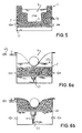
- FIG. 5 in which a body-shaped tub is shown in cross section, in which the tub upper chamber 5 is separated from the tub lower chamber 7 by a fixed partition 3.
- the layer or chamber 11 provided below the partition 3 is provided, for example, with a filling 13 similar to particles or granules, the specific weight of which is preferably less than water or at least less than the specific weight of the circulating heat medium. Due to the buoyancy forces, the particles settle from the underside to the partition 3 of the body-shaped tub, so that convection in the desired sense is largely avoided and, above all, only a conductive heat transfer into the upper tub space is made possible into the body.
- any convective heat transfer can be achieved at any time.
- a filling 13 can also be provided, in particular in the last-mentioned exemplary embodiment, which can generally be referred to as a convection-inhibiting layer or chamber 11.
- This layer can consist, for example, of a filling which is generally in the form of a multi-woven or multi-sieve.
- a honeycomb-like or multi-micro-chamber structure can also be provided, which is difficult to flow through or, in extreme cases, can only be flushed around, in order to heat these materials accordingly, especially between two bathing processes, which serve as the actual heat transfer medium, more than the flushable medium located between them.
- the lower chamber 11 is filled only to such an extent that the particles, which preferably float due to the buoyancy forces, cover and cover at least the solid partition wall at its deepest point with a sufficient layer thickness downwards. Complete filling is also possible at any time.
- FIGS. 6a and 6b A further exemplary embodiment with a lifting device 43 is explained with reference to FIGS. 6a and 6b has at least in part similarity to the compensation chamber 15.
- liquid or pasty medium is only filled up to a partial height 45.
- the air can flow out after opening an outlet valve, via which the liquid partial height 45 can be variably adjusted and, for example, can also completely fill the film subspace.
- a granular filling 13 is whirled up in the film subspace within the liquid to pasty medium or even carried along with the liquid to pasty medium in the circulation system shown via lines when an inflow and outflow line is opened accordingly.
- the convection-inhibiting layer 11 is now to be arranged immediately below the film and, in a further step, the optimal shape, which is tailored to the patient and is preselected by his own body, is to be actuated in the illustration according to FIG
- the granular filling 13 is raised via the platform 49 until the entire space above the platform 49 and below the separating film 3 is filled. Since in this situation all inlets and outlets are easiest to be blocked, the lifting device tends to raise the separating film 3 further upwards, in the sense of an increase in the total volume of the space below the separating film 3, which ultimately creates a vacuum which leads to Compression of the filling 13 against one another and thus leads to the achievement of a "solidification" or "fixation” of the filling 13.
- the liquid medium around the lifting platform 49 or flow through flow openings introduced into it, so that there is in the space below the lifting platform 49 is also still the liquid and / or pasty medium.
- the partial height 45 of the liquid to pasty medium is selected such that at least the underside of the separating film 3 is still wetted.
- the filling level can be chosen differently and, in contrast to the exemplary embodiment shown, be higher or lower.
- the filling materials in particular the granular material, serve as a supplement or, for example, only as a heat reservoir when the liquid level is at a lower level.
- the negative pressure is then released again, so that the granular filling 13 with the liquid medium is whirled up in the pressure balance, flows around it, or is even circulated with the liquid medium in the entire line system via a heating or cooling device, ie after the pressure has been restored to the ambient pressure, even with the lifting platform 49 raised, a convective heat transfer rather than a conductive heat transfer to the film surface is produced.
Landscapes
- Health & Medical Sciences (AREA)
- Public Health (AREA)
- Epidemiology (AREA)
- General Health & Medical Sciences (AREA)
- Pain & Pain Management (AREA)
- Physical Education & Sports Medicine (AREA)
- Rehabilitation Therapy (AREA)
- Life Sciences & Earth Sciences (AREA)
- Animal Behavior & Ethology (AREA)
- Veterinary Medicine (AREA)
- Devices For Medical Bathing And Washing (AREA)
Applications Claiming Priority (2)
| Application Number | Priority Date | Filing Date | Title |
|---|---|---|---|
| DE4006049 | 1990-02-26 | ||
| DE4006049A DE4006049C2 (de) | 1990-02-26 | 1990-02-26 | Badeeinrichtung zum Verabreichen von Voll- oder Sitzbädern |
Publications (2)
| Publication Number | Publication Date |
|---|---|
| EP0448966A1 true EP0448966A1 (fr) | 1991-10-02 |
| EP0448966B1 EP0448966B1 (fr) | 1994-03-30 |
Family
ID=6401006
Family Applications (1)
| Application Number | Title | Priority Date | Filing Date |
|---|---|---|---|
| EP91102755A Expired - Lifetime EP0448966B1 (fr) | 1990-02-26 | 1991-02-25 | Dispositif, en particulier pour prendre des bains ou bains de siège |
Country Status (3)
| Country | Link |
|---|---|
| EP (1) | EP0448966B1 (fr) |
| AT (1) | ATE103480T1 (fr) |
| DE (1) | DE4042506C2 (fr) |
Cited By (5)
| Publication number | Priority date | Publication date | Assignee | Title |
|---|---|---|---|---|
| WO1993008764A1 (fr) * | 1991-11-05 | 1993-05-13 | Michael Thomas Stable | Bain de pieds |
| WO2004071261A1 (fr) * | 2003-02-14 | 2004-08-26 | Paul Haslauer | Baignoire, utilisation d'une baignoire de ce type et procede permettant la mise en oeuvre d'une utilisation en position allongee et/ou pour prendre un bain |
| EP1529512A3 (fr) * | 2003-11-06 | 2005-11-09 | Paul Haslauer | Baignoire à double paroi souple |
| JP2013138764A (ja) * | 2011-12-31 | 2013-07-18 | Hiroyuki Kurihara | 温冷熱治療装置 |
| DE102006035129B4 (de) * | 2006-07-30 | 2015-10-22 | Helga Hör | Duschhilfe für pflegebedürftige Personen, insbesondere Schwerstbehinderte |
Citations (4)
| Publication number | Priority date | Publication date | Assignee | Title |
|---|---|---|---|---|
| DE2358174A1 (de) * | 1973-11-22 | 1975-06-05 | Heinz Ulrich Bramann | Lagerbad fuer schwerverbrannte |
| EP0098390A2 (fr) * | 1982-06-08 | 1984-01-18 | Paul Haslauer | Dispositif permettant de prendre des bains ou bains de siège |
| WO1988007346A1 (fr) * | 1987-03-23 | 1988-10-06 | Carlos Frederick Sebastian | Appareil de bain avec isolation par rapport au fluide environnant |
| DE8816075U1 (de) * | 1988-12-24 | 1989-03-23 | Kraft, Bernd, 6330 Wetzlar | Badevorrichtung |
Family Cites Families (10)
| Publication number | Priority date | Publication date | Assignee | Title |
|---|---|---|---|---|
| DE2355582A1 (de) * | 1973-11-07 | 1975-05-15 | Erwin Damrau | Badebank fuer badewannen |
| DE2444611A1 (de) * | 1974-09-16 | 1976-03-25 | Jacob Herbert Wittenberg | Badelift |
| GB1582332A (en) * | 1977-03-31 | 1981-01-07 | Tideslock Ltd | Supporting apparatus |
| US4137612A (en) * | 1977-04-06 | 1979-02-06 | Kelley Robert V | Buoyant pellet covering for swimming pools |
| US4254517A (en) * | 1979-07-10 | 1981-03-10 | Herman Jr Harry H | Bathtub cushion lift assembly |
| DE3046628C2 (de) * | 1980-12-11 | 1983-03-03 | Paul A-5020 Salzburg Haslauer | Vorrichtung zum Verabreichen von Peloid-Voll- oder Sitzbädern |
| DE3221647C2 (de) * | 1980-12-11 | 1987-02-26 | Paul Salzburg Haslauer | Vorrichtung zum Verabreichen von Voll- oder Sitzbädern |
| EP0081254A1 (fr) * | 1981-12-07 | 1983-06-15 | Edward Heirman | Installation de psammatothérapie c'est-à-dire de traitement du corps par du sable chaud |
| US4541418A (en) * | 1982-08-25 | 1985-09-17 | J. A. Preston Corporation | Simulated hydrotherapy bath |
| DE3333778C2 (de) * | 1983-09-19 | 1985-10-24 | Paul Salzburg Haslauer | Verfahren zur lokalen Wärmebehandlung mittels Packungen und Vorrichtung hierfür |
-
1990
- 1990-02-26 DE DE4042506A patent/DE4042506C2/de not_active Expired - Fee Related
-
1991
- 1991-02-25 AT AT91102755T patent/ATE103480T1/de not_active IP Right Cessation
- 1991-02-25 EP EP91102755A patent/EP0448966B1/fr not_active Expired - Lifetime
Patent Citations (4)
| Publication number | Priority date | Publication date | Assignee | Title |
|---|---|---|---|---|
| DE2358174A1 (de) * | 1973-11-22 | 1975-06-05 | Heinz Ulrich Bramann | Lagerbad fuer schwerverbrannte |
| EP0098390A2 (fr) * | 1982-06-08 | 1984-01-18 | Paul Haslauer | Dispositif permettant de prendre des bains ou bains de siège |
| WO1988007346A1 (fr) * | 1987-03-23 | 1988-10-06 | Carlos Frederick Sebastian | Appareil de bain avec isolation par rapport au fluide environnant |
| DE8816075U1 (de) * | 1988-12-24 | 1989-03-23 | Kraft, Bernd, 6330 Wetzlar | Badevorrichtung |
Cited By (7)
| Publication number | Priority date | Publication date | Assignee | Title |
|---|---|---|---|---|
| WO1993008764A1 (fr) * | 1991-11-05 | 1993-05-13 | Michael Thomas Stable | Bain de pieds |
| GB2275860A (en) * | 1991-11-05 | 1994-09-14 | Michael Thomas Stable | Foot bath |
| GB2275860B (en) * | 1991-11-05 | 1995-05-31 | Michael Thomas Stable | Foot bath |
| WO2004071261A1 (fr) * | 2003-02-14 | 2004-08-26 | Paul Haslauer | Baignoire, utilisation d'une baignoire de ce type et procede permettant la mise en oeuvre d'une utilisation en position allongee et/ou pour prendre un bain |
| EP1529512A3 (fr) * | 2003-11-06 | 2005-11-09 | Paul Haslauer | Baignoire à double paroi souple |
| DE102006035129B4 (de) * | 2006-07-30 | 2015-10-22 | Helga Hör | Duschhilfe für pflegebedürftige Personen, insbesondere Schwerstbehinderte |
| JP2013138764A (ja) * | 2011-12-31 | 2013-07-18 | Hiroyuki Kurihara | 温冷熱治療装置 |
Also Published As
| Publication number | Publication date |
|---|---|
| EP0448966B1 (fr) | 1994-03-30 |
| ATE103480T1 (de) | 1994-04-15 |
| DE4042506C2 (de) | 1995-07-13 |
Similar Documents
| Publication | Publication Date | Title |
|---|---|---|
| DE2140559C2 (de) | Vorrichtung zur inneren Human-Wassertherapie | |
| EP0448966B1 (fr) | Dispositif, en particulier pour prendre des bains ou bains de siège | |
| DE202012012623U1 (de) | Beinlagerkissen | |
| DE4006049C2 (de) | Badeeinrichtung zum Verabreichen von Voll- oder Sitzbädern | |
| DE2953328A1 (en) | Seat cushion or bed cushion | |
| DE3046628A1 (de) | Verfahren zum verabreichen von peloid-voll- oder sitzbaedern an patienten sowie vorrichtung zur durchfuehrung des verfahrens | |
| EP1916973B1 (fr) | Dispositif en vue de l'execution d'une application | |
| DE2929334A1 (de) | Badeeinrichtung fuer bewegungsbehinderte personen | |
| DE10351770B3 (de) | Folienwanne sowie Verfahren zur Bereitstellung einer derartigen Wanne | |
| DE10306280B4 (de) | Wanne, insbesondere zur Durchführung einer Liege- und/oder Badeanwendung, Verwendung einer derartigen Wanne sowie Verfahren zur Durchführung einer Liege- und/oder Badeanwendung | |
| DE10245978B4 (de) | Badeliege | |
| DE4333842C1 (de) | Vorrichtung zur Lagerung eines lebenden insbesondere menschlichen Körpers zur operativen/postoperativen Behandlung | |
| WO1987002235A1 (fr) | Cuve de lavage et de soins | |
| DE8631059U1 (de) | Hängeweste | |
| DE19603226A1 (de) | Einrichtung zum Transport handlungsunfähiger oder verletzter Personen | |
| EP1246559A2 (fr) | Reservoir a liquide flexible pour bain en immersion totale et reserve de liquide | |
| DE2413868C3 (de) | Einrichtung zur Behandlung von Patienten durch Unterwassermassage | |
| DE19850993A1 (de) | Wirbelsäulen-Stütze | |
| DE202006019845U1 (de) | Behandlungsliege | |
| DE1942837C3 (de) | Vorrichtung zur Abstützung eines Körperteiles einer Person | |
| WO1987003800A2 (fr) | Baignoire pour bains ou douches | |
| DE102008008225A1 (de) | Badewannen-Lifter mit Whirlfunktion | |
| DE29505289U1 (de) | Gerät zum auftriebsgestützten, schwimmähnlichen, trockenen und einwirkenden Lagern von Menschen | |
| WO2019192720A1 (fr) | Siège de wc | |
| DE2628248A1 (de) | Sprudelvorrichtung fuer die behandlung des menschlichen koerpers |
Legal Events
| Date | Code | Title | Description |
|---|---|---|---|
| PUAI | Public reference made under article 153(3) epc to a published international application that has entered the european phase |
Free format text: ORIGINAL CODE: 0009012 |
|
| AK | Designated contracting states |
Kind code of ref document: A1 Designated state(s): AT DE FR IT NL |
|
| 17P | Request for examination filed |
Effective date: 19920307 |
|
| 17Q | First examination report despatched |
Effective date: 19920810 |
|
| GRAA | (expected) grant |
Free format text: ORIGINAL CODE: 0009210 |
|
| AK | Designated contracting states |
Kind code of ref document: B1 Designated state(s): AT DE FR IT NL |
|
| REF | Corresponds to: |
Ref document number: 103480 Country of ref document: AT Date of ref document: 19940415 Kind code of ref document: T |
|
| REF | Corresponds to: |
Ref document number: 59101251 Country of ref document: DE Date of ref document: 19940505 |
|
| ITF | It: translation for a ep patent filed | ||
| ET | Fr: translation filed | ||
| PLBE | No opposition filed within time limit |
Free format text: ORIGINAL CODE: 0009261 |
|
| STAA | Information on the status of an ep patent application or granted ep patent |
Free format text: STATUS: NO OPPOSITION FILED WITHIN TIME LIMIT |
|
| 26N | No opposition filed | ||
| PGFP | Annual fee paid to national office [announced via postgrant information from national office to epo] |
Ref country code: NL Payment date: 20060215 Year of fee payment: 16 Ref country code: FR Payment date: 20060215 Year of fee payment: 16 |
|
| PGFP | Annual fee paid to national office [announced via postgrant information from national office to epo] |
Ref country code: AT Payment date: 20060220 Year of fee payment: 16 |
|
| PGFP | Annual fee paid to national office [announced via postgrant information from national office to epo] |
Ref country code: IT Payment date: 20060228 Year of fee payment: 16 |
|
| PGFP | Annual fee paid to national office [announced via postgrant information from national office to epo] |
Ref country code: DE Payment date: 20060425 Year of fee payment: 16 |
|
| NLV4 | Nl: lapsed or anulled due to non-payment of the annual fee |
Effective date: 20070901 |
|
| PG25 | Lapsed in a contracting state [announced via postgrant information from national office to epo] |
Ref country code: AT Free format text: LAPSE BECAUSE OF NON-PAYMENT OF DUE FEES Effective date: 20070225 |
|
| REG | Reference to a national code |
Ref country code: FR Ref legal event code: ST Effective date: 20071030 |
|
| PG25 | Lapsed in a contracting state [announced via postgrant information from national office to epo] |
Ref country code: NL Free format text: LAPSE BECAUSE OF NON-PAYMENT OF DUE FEES Effective date: 20070901 Ref country code: DE Free format text: LAPSE BECAUSE OF NON-PAYMENT OF DUE FEES Effective date: 20070901 |
|
| PG25 | Lapsed in a contracting state [announced via postgrant information from national office to epo] |
Ref country code: FR Free format text: LAPSE BECAUSE OF NON-PAYMENT OF DUE FEES Effective date: 20070228 |
|
| PG25 | Lapsed in a contracting state [announced via postgrant information from national office to epo] |
Ref country code: IT Free format text: LAPSE BECAUSE OF NON-PAYMENT OF DUE FEES Effective date: 20070225 |