EP0449003A2 - Appareil pour refroidir des bandes laminées - Google Patents
Appareil pour refroidir des bandes laminées Download PDFInfo
- Publication number
- EP0449003A2 EP0449003A2 EP91103452A EP91103452A EP0449003A2 EP 0449003 A2 EP0449003 A2 EP 0449003A2 EP 91103452 A EP91103452 A EP 91103452A EP 91103452 A EP91103452 A EP 91103452A EP 0449003 A2 EP0449003 A2 EP 0449003A2
- Authority
- EP
- European Patent Office
- Prior art keywords
- spray
- spray bars
- roller table
- shielding plates
- bars
- Prior art date
- Legal status (The legal status is an assumption and is not a legal conclusion. Google has not performed a legal analysis and makes no representation as to the accuracy of the status listed.)
- Granted
Links
Images


Classifications
-
- B—PERFORMING OPERATIONS; TRANSPORTING
- B21—MECHANICAL METAL-WORKING WITHOUT ESSENTIALLY REMOVING MATERIAL; PUNCHING METAL
- B21B—ROLLING OF METAL
- B21B45/00—Devices for surface or other treatment of work, specially combined with or arranged in, or specially adapted for use in connection with, metal-rolling mills
- B21B45/02—Devices for surface or other treatment of work, specially combined with or arranged in, or specially adapted for use in connection with, metal-rolling mills for lubricating, cooling, or cleaning
- B21B45/0203—Cooling
- B21B45/0209—Cooling devices, e.g. using gaseous coolants
- B21B45/0215—Cooling devices, e.g. using gaseous coolants using liquid coolants, e.g. for sections, for tubes
- B21B45/0233—Spray nozzles, Nozzle headers; Spray systems
-
- B—PERFORMING OPERATIONS; TRANSPORTING
- B21—MECHANICAL METAL-WORKING WITHOUT ESSENTIALLY REMOVING MATERIAL; PUNCHING METAL
- B21B—ROLLING OF METAL
- B21B37/00—Control devices or methods specially adapted for metal-rolling mills or the work produced thereby
- B21B37/74—Temperature control, e.g. by cooling or heating the rolls or the product
- B21B37/76—Cooling control on the run-out table
-
- C—CHEMISTRY; METALLURGY
- C21—METALLURGY OF IRON
- C21D—MODIFYING THE PHYSICAL STRUCTURE OF FERROUS METALS; GENERAL DEVICES FOR HEAT TREATMENT OF FERROUS OR NON-FERROUS METALS OR ALLOYS; MAKING METAL MALLEABLE, e.g. BY DECARBURISATION OR TEMPERING
- C21D1/00—General methods or devices for heat treatment, e.g. annealing, hardening, quenching or tempering
- C21D1/62—Quenching devices
- C21D1/667—Quenching devices for spray quenching
-
- C—CHEMISTRY; METALLURGY
- C21—METALLURGY OF IRON
- C21D—MODIFYING THE PHYSICAL STRUCTURE OF FERROUS METALS; GENERAL DEVICES FOR HEAT TREATMENT OF FERROUS OR NON-FERROUS METALS OR ALLOYS; MAKING METAL MALLEABLE, e.g. BY DECARBURISATION OR TEMPERING
- C21D9/00—Heat treatment, e.g. annealing, hardening, quenching or tempering, adapted for particular articles; Furnaces therefor
- C21D9/52—Heat treatment, e.g. annealing, hardening, quenching or tempering, adapted for particular articles; Furnaces therefor for wires; for strips ; for rods of unlimited length
- C21D9/54—Furnaces for treating strips or wire
- C21D9/56—Continuous furnaces for strip or wire
- C21D9/573—Continuous furnaces for strip or wire with cooling
-
- B—PERFORMING OPERATIONS; TRANSPORTING
- B21—MECHANICAL METAL-WORKING WITHOUT ESSENTIALLY REMOVING MATERIAL; PUNCHING METAL
- B21B—ROLLING OF METAL
- B21B2263/00—Shape of product
- B21B2263/04—Flatness
Definitions
- the invention relates to a device for cooling preferably rolled strips on cooling roller tables in rolling mills with at least two spray bars arranged one behind the other in the direction of movement of the strips and oriented transversely to the direction of movement, each having at least one coolant outlet opening, the total width provided with coolant openings essentially corresponding to the maximum rolled strip width .
- Such cooling devices are already known in large numbers. They can be used to achieve temperature accuracies over the strip length of up to +/- 15 o C for approx. 95% of the strip length. However, temperature differences of more than 50 o C often occur across the bandwidth. The temperature differences across the strip are due to strip profile deviations, different coolant quantity distribution on the rolled strip, different coolant temperatures across the rolled strip width, different cooling effects below and above the rolled strip, different temperature profiles of the incoming strip and much more.
- the object of the invention is to show a cooling device of the generic type with which the rolled strip can be cooled both in the longitudinal direction and in the transverse direction with very small temperature tolerances.
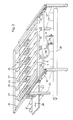
- Fig. 1 the cooling device according to the invention is shown between the last stand 1 of the rolling mill and the driver 2 and the reel 3 for the rolled strip.
- Eight groups of spray bars 4 to 11 are provided along the cooling section, of which two groups 4, 5; 6, 7; 8, 9; 10, 11 are nested.
- Each group of spray bars 4 to 11 has a displacement drive 12, 12 'to 19, 19' at its two ends.
- the groups of spray bars 4 to 11 can be displaced horizontally transversely to the belt running direction 20 via the displacement drives 12, 12 'to 19, 19'.
- the two displacement drives 12, 12 'and .... or 19, 19' of a spray bar group 4 to 11 are acted upon equally.
- the spray bar groups 4 to 11 can, however, be displaced from one another to the same extent or in opposite directions.
- FIG. 2 shows the roller table 21 on which the rolled strip 22 is transported in the strip running direction 20.
- the spray bar groups 4, 5 are interleaved in such a way that mutual displacement perpendicular to the tape running direction 20 is possible without hindrance, but that the openings of the spray tubes 25 and the spray bars 26 lie in a common horizontal plane above the cooling roller table 21, so that therefore none Differences in the coolant distribution can occur.
- the spray bar groups 4, 5 can be displaced relative to one another via the displacement drives 12, 12 'or the displacement drives 13, 13' (not shown).
- the roller table 21 In the extremely retracted position of the sliding drives 12, 12 '; 13, 13 ', the roller table 21 is freely accessible from above without the spray bars 26, 27 blocking access.
- a pivoting of the spray bars, as was necessary according to the prior art, in order to access the rolling stock 22 in the event of a fault, is unnecessary in this mode of operation.
- the movable spray bar groups can only be moved by small distances, thereby being constantly arranged above the roller table 22 and pivoted out of the area above the roller table 22 in the event of a fault will.
- the coolant supply line 28 is also arranged next to the roller table 21.
- the spray bar groups 4, 5 are connected to the supply line 28 via valves 29, 29 'and hose lines 30, 31.
- FIG. 3 shows the spray bar groups 4, 5 and 6, 7 guided on the I-beams 24, 24 'and supported on the stands 23, 23' in a side view.
- the spray bar group 4 is via rollers 32, 32 '; 33, 33 'on the I-beams 24, 24', while the spray bar group 5 over the rollers 34, 34 '; 35, 35 'is guided.
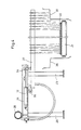
- 4 shows the displacement principle on a single spray bar, not shown in a group.
- 4 shows the roller table 21 on which the rolled strip 22 is transported.
- a spray bar 27 can be seen above the belt and is guided on the I-beam 24 via the rollers 34, 35.
- the I-beam 24 is supported on the stand 23, 23 ''.
- the supply line 28 is shown here above the I-beam 24, so that the corridor between the stands 23, 23 '' remains free.
- the displacement drive 12 acts on the one hand on the I-beam 24 and on the other hand on the roller 34.
- the spray bar 27 can be moved to the left or right in FIG. 4. In the position shown, e.g. the left part of the belt 22 is not directly exposed to coolant. If, however, the spray bar 27 is moved all the way to the left, the roller table 21 from above is e.g. freely accessible with a crane for inspection or repair purposes.
- coolant collecting boxes 36, 37 are provided, which collect the coolant from the spray pipes that protrude beyond the belt edge and return them to the coolant circuit.
- FIG. 5a shows one of several possibilities of the spray tube arrangement.
- the upper part of FIG. 5a shows the spray tube openings of the spray bar 26, while the lower part of FIG. 5a shows the spray tube openings of the spray bar 27 shows.
- the tubes here have the same diameter, but are arranged at an uneven distance from one another.
- the spray tubes of the spray bar 26 are distributed in mirror image to the spray tubes of the spray bar 27.
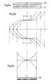
- FIG. 5b shows the specific water quantity distribution of the spray bars as seen across their width.
- the upper part of FIG. 5b shows the water quantity distribution of the spray bar 26 while in the lower part of FIG. 5b the cooling quantity distribution of the spray bar 27 is plotted.
- the different distances between the spray pipes on the different spray bars can be clearly recognized by the different cooling quantity distribution.
- the mirrored curve of the cooling quantity distribution can also be clearly recognized from the distribution curves shown here.
- FIG. 5b shows, in addition to the middle position of the two spray bars shown with a solid line, a left-shifted position of the spray bar 26 (dash-dotted line) and a right-shifted position of the spray bar 26 (dashed line). A left-shifted position (dashed line) and a right-shifted position (dash-dotted line) are also shown for the spray bar 27.
- the addition of the water quantities of both spray bars can be seen in the summation diagram according to FIG. 5c.
- the solid line shows the total amount of water with the spray bar set in the center.
- the dash-dotted line shows the total amount of water with the spray bar 26 shifted to the left and the spray bar 27 shifted to the right, while the dashed line shows the total amount of water with the spray bar 26 shifted to the right and the spray bar 27 shifted to the left.
- FIGS. 5d and 5e correspond to FIGS. 5b and 5c. However, they show the water quantity distribution and water quantity total for a spray bar 26 with a continuously increasing number of spray tubes from left to right, while the water quantity distribution for the spray bar 27 is shown with a continuously decreasing number of spray tubes from left to right.
- 5f shows spray bars 26 and 27 with continuous spray pipe distribution.
- the distribution of the specific water exposure with these spray bars is constant.
- a belt edge-oriented cooling can be achieved by moving the spray bar.
- 5g shows another alternative with which optimal strip edge-oriented cooling is achieved.
- the cooling device according to the invention with cooling bars displaceable transversely to the strip running direction can be combined with shielding plates which can cover spray pipes by corresponding displacement, so that the coolant of the covered spray pipes does not get onto the rolled strip.
- FIG. 6a to 6c show shielding plates and their use in the cooling device according to the invention.
- spray nozzle rows 38 are shown in FIG. 6b, which, as not shown here, can also be designed to be axially displaceable.
- a shielding plate 39 can be seen between the roller table 21 and the spray nozzle rows 38.
- 6a shows the roller table rollers 21 ', 21''... of the roller table 21, between which the spray nozzle rows or groups of spray nozzle rows 38, 38' ... are arranged. Between the spray nozzle rows 38, 38 '... and the Roller table rollers 21 ', 21''... shielding plates 39, 39' ... are shown.
- the shielding plates 39 can have a shape as shown in FIG. 6c, for example a rectangular shape, on the one long side of which a substantially trapezoidal cutout or comb-like cutouts are provided.
- 6a shows that the shielding plates 39, 39 '... are connected to one another at their ends projecting beyond the roller table 21. Each of the connected sides is provided with drives 40, 41 which can cause the shielding plates 39, 39 '... to be displaced in or against the direction of travel of the strip.
- the spray nozzle rows 38, 38 '... are more or less covered, so that any influence on the water distribution is possible, especially in the edge region of the rolled strip.
- the shielding plates 38 shown below the roller table can additionally or alternatively also be arranged above the roller table 21.
- vertical walls and a drain in the shielding trough formed in this way would have to be provided at the edges of the shielding plates, so that the coolant cannot run off the edges of the shielding plates and get onto the rolled strip.
- Vertical walls also make sense for shielding plates provided on the underside of the rolled strip. These vertical plates prevent the cooling medium striking the shielding plate from spreading sideways and from being able to obstruct neighboring rays.
- the coolant distribution on the rolled strip can thus be achieved by the mutual displacement of the spray bars or spray nozzle rows, by the choice of the spacing of the spray tubes and spray nozzles, by the choice of the diameter of the spray tubes, by the position of the shielding plates and by adjust the position of the valves to any complexity, so that optimal cooling is achieved not only over the length of the rolled strip, but also over its width.
- this control principle can be used to set the displacement of the spray bars or spray nozzle rows, the amount of coolant and the shielding plate displacement.
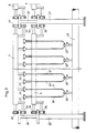
- At least three temperature sensors 42, 42 ', 42''arranged transversely to the direction of travel 20 of the rolled strip 22 are provided behind the last roll stand 1.
- An identical temperature sensor group 34, 34 ', 34'' is provided in the middle of the cooling section and a further temperature sensor group 44, 44', 44 '' in front of the driver 2.
- the temperature sensors 42 to 44 '' work on a computer 45 which adjusts the displacement of the spray bars 26, 27 or the spray bar groups 4 to 11 and the spray nozzle rows or the groups of spray nozzle rows 38, 38 '... the setting of the valves 29 and the shielding plates 39 in dependence on predetermined temperature profiles and further parameters, as well as physical laws. Additionally or alternatively, the regulation can also take place as a function of the signals from strip flatness measuring devices 46, 47.
Landscapes
- Chemical & Material Sciences (AREA)
- Engineering & Computer Science (AREA)
- Mechanical Engineering (AREA)
- Materials Engineering (AREA)
- Thermal Sciences (AREA)
- Crystallography & Structural Chemistry (AREA)
- Physics & Mathematics (AREA)
- Metallurgy (AREA)
- Organic Chemistry (AREA)
- Heat Treatment Of Strip Materials And Filament Materials (AREA)
- Heat Treatments In General, Especially Conveying And Cooling (AREA)
- Metal Rolling (AREA)
- Veneer Processing And Manufacture Of Plywood (AREA)
Applications Claiming Priority (2)
| Application Number | Priority Date | Filing Date | Title |
|---|---|---|---|
| DE4009868 | 1990-03-28 | ||
| DE4009868A DE4009868A1 (de) | 1990-03-28 | 1990-03-28 | Vorrichtung zum kuehlen von walzband |
Publications (3)
| Publication Number | Publication Date |
|---|---|
| EP0449003A2 true EP0449003A2 (fr) | 1991-10-02 |
| EP0449003A3 EP0449003A3 (en) | 1992-03-18 |
| EP0449003B1 EP0449003B1 (fr) | 1994-11-30 |
Family
ID=6403189
Family Applications (1)
| Application Number | Title | Priority Date | Filing Date |
|---|---|---|---|
| EP91103452A Expired - Lifetime EP0449003B1 (fr) | 1990-03-28 | 1991-03-07 | Appareil pour refroidir des bandes laminées |
Country Status (3)
| Country | Link |
|---|---|
| EP (1) | EP0449003B1 (fr) |
| AT (1) | ATE114731T1 (fr) |
| DE (2) | DE4009868A1 (fr) |
Cited By (6)
| Publication number | Priority date | Publication date | Assignee | Title |
|---|---|---|---|---|
| WO2001017704A1 (fr) * | 1999-09-10 | 2001-03-15 | Siemens Aktiengesellschaft | Procede et dispositif pour le refroidissement d'un feuillard d'acier lamine a chaud sortant d'une cage de laminoir |
| WO2001047647A3 (fr) * | 1999-12-27 | 2001-11-29 | Siemens Ag | Procede et dispositif pour refroidir une bande metallique laminee a chaud sortant d'une cage de laminoir |
| EP2178658A4 (fr) * | 2007-08-17 | 2013-07-17 | Outokumpu Oy | Procédé et équipement de réglage de la planéité lors du refroidissement d'une bande d'acier inoxydable |
| EP2969279B1 (fr) | 2013-03-11 | 2017-11-15 | Novelis Inc. | Amélioration de la planéité d'une bande laminée |
| EP3395463A1 (fr) * | 2017-04-26 | 2018-10-31 | Primetals Technologies Austria GmbH | Refroidissement d'un laminé |
| EP3774100B1 (fr) | 2018-04-13 | 2022-06-29 | SMS Group GmbH | Dispositif de refroidissement servant à refroidir un produit métallique et procédé permettant sa fabrication et son fonctionnement |
Families Citing this family (4)
| Publication number | Priority date | Publication date | Assignee | Title |
|---|---|---|---|---|
| DE19758466B4 (de) * | 1997-03-11 | 2007-10-04 | Betriebsforschungsinstitut VDEh - Institut für angewandte Forschung GmbH | Planheits-Regelungssystem für Metallband |
| DE102008009481A1 (de) | 2008-02-15 | 2009-08-20 | Basf Coatings Ag | Wässrige Beschichtungszusammensetzung, Verfahren zur Herstellung und ihre Verwendung |
| DE102017206540A1 (de) * | 2017-04-18 | 2018-10-18 | Sms Group Gmbh | Vorrichtung und Verfahren zum Kühlen von Metallbändern oder -blechen |
| JP7103511B2 (ja) * | 2019-09-30 | 2022-07-20 | Jfeスチール株式会社 | 金属帯急冷装置及び金属帯急冷方法並びに金属帯製品の製造方法 |
Family Cites Families (3)
| Publication number | Priority date | Publication date | Assignee | Title |
|---|---|---|---|---|
| JPS5832511A (ja) * | 1981-08-21 | 1983-02-25 | Nippon Kokan Kk <Nkk> | 厚鋼板の冷却方法 |
| DE3146657A1 (de) * | 1981-11-25 | 1983-06-01 | SMS Schloemann-Siemag AG, 4000 Düsseldorf | Vorrichtung zum kuehlen von flachem walzgut |
| US4899547A (en) * | 1988-12-30 | 1990-02-13 | Even Flow Products, Inc. | Hot strip mill cooling system |
-
1990
- 1990-03-28 DE DE4009868A patent/DE4009868A1/de not_active Withdrawn
-
1991
- 1991-03-07 DE DE59103613T patent/DE59103613D1/de not_active Expired - Fee Related
- 1991-03-07 AT AT91103452T patent/ATE114731T1/de not_active IP Right Cessation
- 1991-03-07 EP EP91103452A patent/EP0449003B1/fr not_active Expired - Lifetime
Cited By (11)
| Publication number | Priority date | Publication date | Assignee | Title |
|---|---|---|---|---|
| WO2001017704A1 (fr) * | 1999-09-10 | 2001-03-15 | Siemens Aktiengesellschaft | Procede et dispositif pour le refroidissement d'un feuillard d'acier lamine a chaud sortant d'une cage de laminoir |
| WO2001047647A3 (fr) * | 1999-12-27 | 2001-11-29 | Siemens Ag | Procede et dispositif pour refroidir une bande metallique laminee a chaud sortant d'une cage de laminoir |
| EP2178658A4 (fr) * | 2007-08-17 | 2013-07-17 | Outokumpu Oy | Procédé et équipement de réglage de la planéité lors du refroidissement d'une bande d'acier inoxydable |
| KR101453129B1 (ko) * | 2007-08-17 | 2014-10-27 | 오또꿈뿌 오와이제이 | 스테인리스강 스트립의 냉각시의 평평함 제어 방법 및 장치 |
| EP2969279B1 (fr) | 2013-03-11 | 2017-11-15 | Novelis Inc. | Amélioration de la planéité d'une bande laminée |
| EP2969279B2 (fr) † | 2013-03-11 | 2024-04-03 | Novelis Inc. | Amélioration de la planéité d'une bande laminée |
| EP3395463A1 (fr) * | 2017-04-26 | 2018-10-31 | Primetals Technologies Austria GmbH | Refroidissement d'un laminé |
| WO2018197100A3 (fr) * | 2017-04-26 | 2018-12-27 | Primetals Technologies Austria GmbH | Refroidissement d'un produit laminé |
| US11358195B2 (en) | 2017-04-26 | 2022-06-14 | Primetals Technologies Austria GmbH | Cooling of rolled matertial |
| US11786949B2 (en) | 2017-04-26 | 2023-10-17 | Primetals Technologies Austria GmbH | Cooling of rolled material |
| EP3774100B1 (fr) | 2018-04-13 | 2022-06-29 | SMS Group GmbH | Dispositif de refroidissement servant à refroidir un produit métallique et procédé permettant sa fabrication et son fonctionnement |
Also Published As
| Publication number | Publication date |
|---|---|
| EP0449003A3 (en) | 1992-03-18 |
| EP0449003B1 (fr) | 1994-11-30 |
| DE4009868A1 (de) | 1991-10-02 |
| DE59103613D1 (de) | 1995-01-12 |
| ATE114731T1 (de) | 1994-12-15 |
Similar Documents
| Publication | Publication Date | Title |
|---|---|---|
| DE4309986A1 (de) | Verfahren und Vorrichtung zum Walzen eines Walzbandes | |
| DE2310116A1 (de) | Kuehlmittelregelung fuer warmbandwalzenstrassen | |
| DE3885019T2 (de) | Verfahren und Vorrichtung zum Richten eines metallischen Bandes. | |
| EP0449003B1 (fr) | Appareil pour refroidir des bandes laminées | |
| DE3247459C2 (de) | Vorrichtung zum Behandeln von bahnförmigen Materialien mit einem gasförmigen Medium | |
| DE69822715T2 (de) | Seitenführung für eine Speicherstation, mit einer Doppelreihe von Rollen | |
| DE19524729A1 (de) | Verfahren und Vorrichtung zum Walzen von Bändern mit über ihrer Breite ungleichförmige Dicken- und/oder Längenverteilung | |
| EP0513631B1 (fr) | Dispositif pour le refroidissement d'un produit plat, en particulier d'une bande métallique | |
| EP0032536A2 (fr) | Dispositif pour obtenir une distribution de température homogène dans un ruban en acier chaud pendant le procédé de laminage | |
| DE19934557C2 (de) | Vorrichtung zum Kühlen von auf einer Förderstrecke geförderten Metallbändern oder -blechen | |
| DE102016224822A1 (de) | Verfahren zum Walzen eines Walzguts in einer Walzstraße und Walzstraße | |
| EP0383786B1 (fr) | Procede de production d'un rideau d'eau | |
| DE2547416A1 (de) | Vorrichtung zum kuehlen von bandmaterial | |
| DE4337342A1 (de) | Vorrichtung zum Kühlen von Walzbändern | |
| DE3839056C1 (fr) | ||
| DE3533305C2 (fr) | ||
| DE60002456T2 (de) | Hitzeschilder | |
| DE2413302C2 (de) | Mengeneinstellvorrichtung für einen linearen Schlitzauslaß für Lüftungs- und/oder Klimaanlagen | |
| DE3004240A1 (de) | Vorrichtung zum hydraulischen abspritzen bzw. entzundern von walzgut, insbesondere von bloecken mit unterschiedlich grossen querschnittsabmessungen | |
| AT411437B (de) | Vorrichtung zum richten von drahtförmigem material | |
| DE3633423C2 (fr) | ||
| DE4227842C2 (de) | Walzgutführung | |
| AT402807B (de) | Verfahren und vorrichtung zur differenzierten abkühlung von breitflacherzeugnissen | |
| DE2426828A1 (de) | Vorrichtung zum kuehlen von stangenmaterial | |
| DE3634188C2 (fr) |
Legal Events
| Date | Code | Title | Description |
|---|---|---|---|
| PUAI | Public reference made under article 153(3) epc to a published international application that has entered the european phase |
Free format text: ORIGINAL CODE: 0009012 |
|
| 17P | Request for examination filed |
Effective date: 19910327 |
|
| AK | Designated contracting states |
Kind code of ref document: A2 Designated state(s): AT DE FR GB IT NL |
|
| PUAL | Search report despatched |
Free format text: ORIGINAL CODE: 0009013 |
|
| AK | Designated contracting states |
Kind code of ref document: A3 Designated state(s): AT DE FR GB IT NL |
|
| 17Q | First examination report despatched |
Effective date: 19940118 |
|
| GRAA | (expected) grant |
Free format text: ORIGINAL CODE: 0009210 |
|
| AK | Designated contracting states |
Kind code of ref document: B1 Designated state(s): AT DE FR GB IT NL |
|
| REF | Corresponds to: |
Ref document number: 114731 Country of ref document: AT Date of ref document: 19941215 Kind code of ref document: T |
|
| REF | Corresponds to: |
Ref document number: 59103613 Country of ref document: DE Date of ref document: 19950112 |
|
| ITF | It: translation for a ep patent filed | ||
| ET | Fr: translation filed | ||
| PG25 | Lapsed in a contracting state [announced via postgrant information from national office to epo] |
Ref country code: AT Effective date: 19950307 |
|
| GBT | Gb: translation of ep patent filed (gb section 77(6)(a)/1977) |
Effective date: 19950223 |
|
| PLBE | No opposition filed within time limit |
Free format text: ORIGINAL CODE: 0009261 |
|
| STAA | Information on the status of an ep patent application or granted ep patent |
Free format text: STATUS: NO OPPOSITION FILED WITHIN TIME LIMIT |
|
| 26N | No opposition filed | ||
| REG | Reference to a national code |
Ref country code: GB Ref legal event code: IF02 |
|
| PGFP | Annual fee paid to national office [announced via postgrant information from national office to epo] |
Ref country code: GB Payment date: 20020222 Year of fee payment: 12 |
|
| PGFP | Annual fee paid to national office [announced via postgrant information from national office to epo] |
Ref country code: NL Payment date: 20020228 Year of fee payment: 12 |
|
| PGFP | Annual fee paid to national office [announced via postgrant information from national office to epo] |
Ref country code: DE Payment date: 20020309 Year of fee payment: 12 |
|
| PGFP | Annual fee paid to national office [announced via postgrant information from national office to epo] |
Ref country code: FR Payment date: 20020315 Year of fee payment: 12 |
|
| PG25 | Lapsed in a contracting state [announced via postgrant information from national office to epo] |
Ref country code: GB Free format text: LAPSE BECAUSE OF NON-PAYMENT OF DUE FEES Effective date: 20030307 |
|
| PG25 | Lapsed in a contracting state [announced via postgrant information from national office to epo] |
Ref country code: NL Free format text: LAPSE BECAUSE OF NON-PAYMENT OF DUE FEES Effective date: 20031001 Ref country code: DE Free format text: LAPSE BECAUSE OF NON-PAYMENT OF DUE FEES Effective date: 20031001 |
|
| GBPC | Gb: european patent ceased through non-payment of renewal fee |
Effective date: 20030307 |
|
| PG25 | Lapsed in a contracting state [announced via postgrant information from national office to epo] |
Ref country code: FR Free format text: LAPSE BECAUSE OF NON-PAYMENT OF DUE FEES Effective date: 20031127 |
|
| NLV4 | Nl: lapsed or anulled due to non-payment of the annual fee |
Effective date: 20031001 |
|
| REG | Reference to a national code |
Ref country code: FR Ref legal event code: ST |
|
| PG25 | Lapsed in a contracting state [announced via postgrant information from national office to epo] |
Ref country code: IT Free format text: LAPSE BECAUSE OF NON-PAYMENT OF DUE FEES;WARNING: LAPSES OF ITALIAN PATENTS WITH EFFECTIVE DATE BEFORE 2007 MAY HAVE OCCURRED AT ANY TIME BEFORE 2007. THE CORRECT EFFECTIVE DATE MAY BE DIFFERENT FROM THE ONE RECORDED. Effective date: 20050307 |