EP0449008B1 - Sonochemisches Gerät - Google Patents
Sonochemisches Gerät Download PDFInfo
- Publication number
- EP0449008B1 EP0449008B1 EP91103527A EP91103527A EP0449008B1 EP 0449008 B1 EP0449008 B1 EP 0449008B1 EP 91103527 A EP91103527 A EP 91103527A EP 91103527 A EP91103527 A EP 91103527A EP 0449008 B1 EP0449008 B1 EP 0449008B1
- Authority
- EP
- European Patent Office
- Prior art keywords
- coupler
- collar
- wall
- liquid
- chamber
- Prior art date
- Legal status (The legal status is an assumption and is not a legal conclusion. Google has not performed a legal analysis and makes no representation as to the accuracy of the status listed.)
- Expired - Lifetime
Links
- 239000007788 liquid Substances 0.000 claims description 35
- 229910000831 Steel Inorganic materials 0.000 claims description 2
- 239000010959 steel Substances 0.000 claims description 2
- 239000004006 olive oil Substances 0.000 description 6
- 235000008390 olive oil Nutrition 0.000 description 6
- 239000010935 stainless steel Substances 0.000 description 5
- 229910001220 stainless steel Inorganic materials 0.000 description 5
- 229910001069 Ti alloy Inorganic materials 0.000 description 4
- 241000196324 Embryophyta Species 0.000 description 3
- 239000000126 substance Substances 0.000 description 3
- 238000002604 ultrasonography Methods 0.000 description 3
- XLYOFNOQVPJJNP-UHFFFAOYSA-N water Substances O XLYOFNOQVPJJNP-UHFFFAOYSA-N 0.000 description 3
- 238000006243 chemical reaction Methods 0.000 description 2
- 230000008878 coupling Effects 0.000 description 2
- 238000010168 coupling process Methods 0.000 description 2
- 238000005859 coupling reaction Methods 0.000 description 2
- 230000000694 effects Effects 0.000 description 2
- 230000003628 erosive effect Effects 0.000 description 2
- 239000000203 mixture Substances 0.000 description 2
- 239000003921 oil Substances 0.000 description 2
- 235000019198 oils Nutrition 0.000 description 2
- 230000001052 transient effect Effects 0.000 description 2
- 230000003321 amplification Effects 0.000 description 1
- 230000005540 biological transmission Effects 0.000 description 1
- 239000003153 chemical reaction reagent Substances 0.000 description 1
- 230000006835 compression Effects 0.000 description 1
- 238000007906 compression Methods 0.000 description 1
- 238000001816 cooling Methods 0.000 description 1
- 230000008021 deposition Effects 0.000 description 1
- 238000006073 displacement reaction Methods 0.000 description 1
- 239000002305 electric material Substances 0.000 description 1
- 238000004945 emulsification Methods 0.000 description 1
- 230000002708 enhancing effect Effects 0.000 description 1
- 239000011521 glass Substances 0.000 description 1
- 230000020169 heat generation Effects 0.000 description 1
- 238000010438 heat treatment Methods 0.000 description 1
- 230000001939 inductive effect Effects 0.000 description 1
- HFGPZNIAWCZYJU-UHFFFAOYSA-N lead zirconate titanate Chemical compound [O-2].[O-2].[O-2].[O-2].[O-2].[Ti+4].[Zr+4].[Pb+2] HFGPZNIAWCZYJU-UHFFFAOYSA-N 0.000 description 1
- 229910052451 lead zirconate titanate Inorganic materials 0.000 description 1
- 239000012528 membrane Substances 0.000 description 1
- 230000009022 nonlinear effect Effects 0.000 description 1
- 238000003199 nucleic acid amplification method Methods 0.000 description 1
- 238000013021 overheating Methods 0.000 description 1
- 239000013618 particulate matter Substances 0.000 description 1
- 239000000376 reactant Substances 0.000 description 1
- 230000035939 shock Effects 0.000 description 1
- 229920002379 silicone rubber Polymers 0.000 description 1
- 239000004945 silicone rubber Substances 0.000 description 1
- 239000007787 solid Substances 0.000 description 1
- 239000000725 suspension Substances 0.000 description 1
Images


Classifications
-
- B—PERFORMING OPERATIONS; TRANSPORTING
- B06—GENERATING OR TRANSMITTING MECHANICAL VIBRATIONS IN GENERAL
- B06B—METHODS OR APPARATUS FOR GENERATING OR TRANSMITTING MECHANICAL VIBRATIONS OF INFRASONIC, SONIC, OR ULTRASONIC FREQUENCY, e.g. FOR PERFORMING MECHANICAL WORK IN GENERAL
- B06B3/00—Methods or apparatus specially adapted for transmitting mechanical vibrations of infrasonic, sonic, or ultrasonic frequency
-
- B—PERFORMING OPERATIONS; TRANSPORTING
- B01—PHYSICAL OR CHEMICAL PROCESSES OR APPARATUS IN GENERAL
- B01J—CHEMICAL OR PHYSICAL PROCESSES, e.g. CATALYSIS OR COLLOID CHEMISTRY; THEIR RELEVANT APPARATUS
- B01J19/00—Chemical, physical or physico-chemical processes in general; Their relevant apparatus
- B01J19/08—Processes employing the direct application of electric or wave energy, or particle radiation; Apparatus therefor
- B01J19/10—Processes employing the direct application of electric or wave energy, or particle radiation; Apparatus therefor employing sonic or ultrasonic vibrations
-
- B—PERFORMING OPERATIONS; TRANSPORTING
- B01—PHYSICAL OR CHEMICAL PROCESSES OR APPARATUS IN GENERAL
- B01J—CHEMICAL OR PHYSICAL PROCESSES, e.g. CATALYSIS OR COLLOID CHEMISTRY; THEIR RELEVANT APPARATUS
- B01J19/00—Chemical, physical or physico-chemical processes in general; Their relevant apparatus
- B01J19/18—Stationary reactors having moving elements inside
- B01J19/1868—Stationary reactors having moving elements inside resulting in a loop-type movement
- B01J19/1881—Stationary reactors having moving elements inside resulting in a loop-type movement externally, i.e. the mixture leaving the vessel and subsequently re-entering it
-
- B—PERFORMING OPERATIONS; TRANSPORTING
- B01—PHYSICAL OR CHEMICAL PROCESSES OR APPARATUS IN GENERAL
- B01J—CHEMICAL OR PHYSICAL PROCESSES, e.g. CATALYSIS OR COLLOID CHEMISTRY; THEIR RELEVANT APPARATUS
- B01J2219/00—Chemical, physical or physico-chemical processes in general; Their relevant apparatus
- B01J2219/00761—Details of the reactor
- B01J2219/00763—Baffles
- B01J2219/00765—Baffles attached to the reactor wall
- B01J2219/00768—Baffles attached to the reactor wall vertical
Definitions
- This invention relates to apparatus for subjecting a liquid to a high ultrasonic intensity, particularly but not exclusively for inducing or enhancing a chemical reaction in the liquid.
- a liquid is subjected to a high ultrasonic intensity (that is an intensity greater than ahout 1 W/cm2) then there is a significant deposition of energy into the liquid through attenuation and non-linear effects. This may lead to physical changes (for example streaming, mixing, or emulsification) or to chemical changes, and the present invention is principally concerned with the latter, which may be referred to as sonochemistry.
- the most significant sonochemical effects are usually associated with cavitation in the liquid, that is the creation of bubbles of gas or vapour due to the ultrasound and their subsequent collapse, and especially with transient vaporous cavitation which only occurs above an intensity threshold typically above 0.3 W/cm2.
- an ultrasonic wave generator comprising a vibratory member with a hollow cylindrical body coupled to ultrasonic transducer means through an amplification horn directly fixed on the hollow cylindrical body with a bolt screwed from inside the hollow cylindrical body.
- an apparatus for subjecting a liquid to a high ultrasonic intensity comprising means defining a chamber for the liquid, at least one collar fixed to the outside of a wall of the chamber, each collar enclosing part of an ultrasonic coupler adapted to resonate at an operating frequency and having a nodal flange by which it is fixed to the end of the collar remote from the wall such that there is a gap between the sides of the coupler and the collar, and a gap between the end of the coupler and the wall, a low attenuation buffer liquid with a cavitation threshold above that of the liquid in the chamber filling the collar and so occupying the gaps between the coupler and both the collar and the wall, and a transducer assembly fixed to the end of the coupler outside the collar adapted when energised to generate ultrasonic waves of the operating frequency in the coupler.
- the benefits of mounting the transducer and the coupler by means of a nodal flange are that the resonant responses of the means defining the chamber have a minimal effect on the resonant behaviour of the transducer, and that the ultrasonic waves are transmitted into the coupler and then through the buffer liquid and the wall into the liquid in the chamber, rather than into the means defining the chamber.
- the use of a buffer liquid enables cavitation and hence erosion at the end of the coupler to be suppressed, while the presence of a collar surrounding the part of the coupler immersed in buffer liquid suppresses lateral modes of vibration in the coupler.
- the coupler is half a wavelength long (at the operating frequency), is of titanium alloy, and along part of its length is tapered. There is preferably no change in diameter between opposite sides of the nodal flange.
- the end adjacent to the wall is of diameter 50 mm while the other end is of diameter 33 mm.
- the wall itself may be of glass, or stainless steel and in this case is preferably less than 5 mm thick, most preferably 2.5 mm thick, to improve transmission of ultrasound into the liquid in the chamber.
- the collar is desirably of such a length that the gap between the end of the coupler and the nearest part of the wall is less than 10 mm and much less than a quarter wavelength in the buffer liquid, preferably about 6 mm.
- the gap between the sides of the coupler and the collar is preferably less than 10 mm, but preferably no less than 2 mm.
- the collar itself is desirably between 2 and 5 mm thick, preferably about 3 mm thick, and of stainless steel.
- the preferred buffer liquid is olive oil.
- Means are preferably provided to circulate the buffer liquid and to cool it, as there is significant heat generation in the coupler and in the buffer liquid during operation.
- the chamber-defining means comprises a cylindrical stainless-steel tube, and there are three such collars fixed to the outside equally spaced around it, lying in a common plane.
- the tube might be closed at each end to define a closed chamber, or might form part of a longer duct, for example a reaction loop connected at each end to a larger storage vessel.
- the wall to which the collar is fixed is integral with the means defining the chamber for example the wall would desirably be an integral part of the tube defining the chamber, so there is no need for any seal between the buffer liquid in the collar and the liquid in the chamber.
- a chemical treatment plant 10 including a reactor tank 12 provided with a heating and/or cooling jacket 13, internal baffles 14, a stirrer 15 driven by a motor 16, inlets 17 and 18 for reagents and an outlet 19 for a product.
- a loop 20 communicates between two ports 21, 22 in the tank 12, and incorporates a pump 24 so liquids from the tank 12 may be circulated through the loop 20.
- a sonochemical apparatus 25 (shown diagrammatically) forms part of the loop 20, and can be isolated by valves 26.
- the apparatus 25 includes a collar 28 filled with olive oil; the oil is circulated by a pump 27 through a heat exchanger 29 during operation, the circuit including an expansion tank 30 covered by a flexible membrane 31 to ensure the oil does not become contaminated for example by water vapour.
- the liquid being passed through the sonochemical apparatus 25 might be a single phase for example a mixture of water-soluble reactants in water, or might be more than one phase, for example a mixture of two or more immiscible liquids, or particulate matter in suspension.
- the plant 10 might incorporate more than one loop 20 connected to the tank 12, so the flows of liquid in the loops 20 are in parallel; also, within any one loop 20 there might be more than one sonochemical apparatus 25 through which the liquid would flow in series.
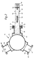
- FIG. 2 there is shown a cross-sectional view of a sonochemical apparatus 25 suitable for use in the loop 20 of Figure 1.
- the apparatus 25 includes a length of stainless steel tube 35 of wall thickness 2.5 mm and bore diameter 125 mm, with a flange 36 (shown in Figure 3) at each end so it can be connected into the loop 20.
- Three stepped stainless steel collars 38 of wall thickness 3 mm are welded to the outside of the tube 35 in a common plane, equally spaced around it; at the outer end of each is a mounting flange 40.
- each collar 38 is provided with inlet ports 42 and outlet ports 44 for circulating olive oil 43 through the collar 38 and a heat exchanger 29 as described above in relation to Figure 1.
- Each collar 38 encloses one end of a generally cylindrical titanium alloy half-wavelength coupler 46 (only one being shown in Figure 2) which has a nodal flange 48.
- the coupler 46 is held coaxial with the collar 38 with its end face 6 mm from the outside of the wall of the tube 35 by clamping the outer edge of the nodal flange 48 between two silicone rubber gaskets 50 held between the mounting flange 40 and a steel clamping ring 52 and secured by screws 54 (only two are shown).
- a transducer assembly 56 To the other end of the coupler 46 is firmly fixed a transducer assembly 56 by means of a short threaded stud 58 which engages in correspondingly threaded holes in the coupler 46 and the assembly 56.
- the abutting faces are smooth and flat to maximize the coupling of ultrasonic waves from the assembly 56 into the coupler 46.
- the resonant frequency of the assembly 56 is 20 kHz
- the coupler 46 is half a wavelength long at that frequency, so that the flange 48 is at a position which in operation is a node of displacement.
- the end of the coupler 46 adjacent to the assembly 56 is 33 mm in diameter (the same diameter as the adjacent end of the assembly 56), but the other end is of diameter 50 mm in order to couple ultrasound more efficiently into the olive oil 43.
- each end is a short cylindrical portion; between the wider end portion and the flange 48 the coupler 46 tapers uniformly; the coupler 46 has the same diameter at each side of the flange 48 and on each side of the flange 48 is a fillet; and between the flange 48 and the narrower end portion is a cylindrical portion and then a short tapered portion.
- the transducer assembly 56 comprises a generally cylindrical titanium alloy coupling block 60 (which also defines a nodal flange 62) and a cylindrical titanium alloy backing block 64, between which are sandwiched two annular discs 66 of pzt (lead zirconate titanate) piezo-electric material polarized in opposite directions.
- the assembly 56 is held together by an 8mm diameter bolt 68 which is tight enough to ensure the discs 66 remain in compression in operation.
- the dimensions and masses are such that the assembly 56 resonates at about 20 kHz.
- Such an assembly is available from Sonic Systems, Isle Brewers, Taunton, Somerset.
- each transducer assembly 56 is connected to a respective 20 kHz signal generator (not shown), the electrical signals being supplied to the adjacent faces of the discs 66 and the outer faces being earthed.
- each generator might provide an electrical power of about 250 W to the assembly 56.
- Olive oil 43 is circulated through the collars 38 and the heat exchanger 29 to prevent overheating. Due to energy losses, principally due to reflection at the interface between the olive oil 43 and the tube 35, the sonic power to which the liquid inside the tube 35 is subjected is about 100 W from each assembly 56. Where the liquid is water, cavitation has been found to occur over a length of the tube 35 of about 300 mm, so the treated volume is about 3.6 litres.
Landscapes
- Chemical & Material Sciences (AREA)
- Organic Chemistry (AREA)
- Chemical Kinetics & Catalysis (AREA)
- Engineering & Computer Science (AREA)
- Mechanical Engineering (AREA)
- Health & Medical Sciences (AREA)
- General Health & Medical Sciences (AREA)
- Toxicology (AREA)
- Physical Or Chemical Processes And Apparatus (AREA)
Claims (12)
- Ein Apparat, um eine Flüssigkeit einer hohen Ultraschallintensität auszusetzen, mit einer Vorrichtung (35), die eine Kammer für die Flüssigkeit bestimmt, und mit einer Wandleranordnung (56), die geeignet ist, wenn sie mit Energie versorgt wird, Ultraschallwellen bei einer Betriebsfrequenz zu erzeugen, dadurch gekennzeichnet, daß wenigstens eine Muffe bzw. ein Kragen (38), die bzw. der an der Außenseite einer Wand (35) der Kammer angebracht ist, wobei jede Muffe bzw. jeder Kragen (38) einen Teil eines Ultraschallkopplungselements (46) umgibt, das angepaßt ist bei der Betriebsfrequenz in Resonanz zu sein, und einen Knotenflansch (48), durch den es an das von der Wand (35) entfernte Ende der Muffe bzw. des Kragens (38) so befestigt ist, daß es einen Zwischenraum zwischen den Seiten des Kopplungselements (46) und der Muffe bzw. des Kragens (38), einen Zwischenraum zwischen dem Ende des Kopplungselements (46) und der Wand (35) gibt, und daß eine leicht dämpfende bzw. abschwächende Pufferflüssigkeit mit einer Kavitationsschwelle oberhalb derjenigen der Flüssigkeit in der Kammer vorgesehen ist, die die Muffe bzw. den Kragen (38) füllt und so die Zwischenräume zwischen dem Kopplungselement (46) und beidem, der Muffe bzw. dem Kragen (38) und der Wand (35), einnimmt, wobei die Wandleranordnung (56) an das außerhalb der Muffe bzw. des Kragens (38) befindliche Ende des Kopplungselements (46) angebracht ist und geeignet ist, wenn sie mit Energie versorgt wird, um Ultraschallwellen mit der. Betriebsfrequenz in dem Kupplungselement (46) zu erzeugen.
- Apparat nach Anspruch 1, bei dem das Kopplungselement (46) bei der Betriebsfrequenz eine halbe Wellenlänge lang ist und zumindest über einen Teil seiner Länge verjüngend zuläuft.
- Apparat nach Anspruch 1 oder 2, bei dem es keine Änderung im Durchmesser des Kopplungselements (46) zwischen den gegenüberliegenden Seiten des Knotenflansches (48) gibt.
- Apparat nach einem der Ansprüche 1 bis 3, bei dem die dem Ende des Kopplungselements (46) benachbarte Wand (35) Stahl beinhaltet und eine Dicke kleiner als 5 mm hat.
- Apparat nach Anspruch 4, bei dem die besagte Wand 2,5 mm dick ist.
- Apparat nach einem der vorhergehenden Ansprüche, bei dem die Muffe bzw. der Kragen (38) von einer solchen Länge ist, daß der Zwischenraum zwischen dem Ende des Kopplungselements (46) und dem nächsten Teil der Wand (35) kleiner als 10 mm ist und viel kleiner ist als ein Viertel der Wellenlänge in der Pufferflüssigkeit bei der Betriebsfrequenz.
- Apparat nach einem der vorhergehenden Ansprüche, bei dem die Muffe bzw. der Kragen (38) von einem solchen Durchmesser ist, daß der Zwischenraum zwischen den Seiten des Kopplungselements (46) und der Muffe bzw. des Kragens (38) zwischen 2 und 10 mm ist.
- Apparat nach einem der vorhergehenden Ansprüche, bei dem die Muffe bzw. der Kragen (38) selbst von einer Dicke zwischen 2 und 5 mm ist.
- Apparat nach einem der vorhergehende Ansprüche, der ebenso eine Vorrichtung (27), um die Pufferflüssigkeit umzuwälzen, und eine Vorrichtung (29), um sie zu kühlen, beinhaltet.
- Apparat nach einem der vorhergehenden Ansprüche, bei dem die Vorrichtung, die eine Kammer für die Flüssigkeit bestimmt, eine zylindrische Röhre (35) aufweist, wobei der Apparat ebenso eine Vorrichtung (24) aufweist, um die Flüssigkeit zu veranlassen, durch die Röhre (35) zu fließen.
- Apparat nach einem der vorhergehenden Ansprüche, bei dem die Wand (35) der Kammer, an die die Muffe bzw. der Kragen (38) angebracht ist, einstückig mit der Vorrichtung (35), die die Kammer bestimmt, ist.
- Apparat nach Anspruch 10, bei dem es drei Muffen bzw. Krägen (38), jede mit einem entsprechenden Kopplungselement (46) und einer Übertragungsanordnung (56), gibt, die an die Außenseite der Röhre (35) festgemacht sind und gleichmäßig um diese räumlich angeordnet sind, wobei sie in einer gemeinsamen Ebene liegen.
Applications Claiming Priority (2)
| Application Number | Priority Date | Filing Date | Title |
|---|---|---|---|
| GB9006989 | 1990-03-28 | ||
| GB909006989A GB9006989D0 (en) | 1990-03-28 | 1990-03-28 | Sonochemical apparatus |
Publications (3)
| Publication Number | Publication Date |
|---|---|
| EP0449008A2 EP0449008A2 (de) | 1991-10-02 |
| EP0449008A3 EP0449008A3 (en) | 1991-12-11 |
| EP0449008B1 true EP0449008B1 (de) | 1994-07-20 |
Family
ID=10673444
Family Applications (1)
| Application Number | Title | Priority Date | Filing Date |
|---|---|---|---|
| EP91103527A Expired - Lifetime EP0449008B1 (de) | 1990-03-28 | 1991-03-08 | Sonochemisches Gerät |
Country Status (5)
| Country | Link |
|---|---|
| US (1) | US5658534A (de) |
| EP (1) | EP0449008B1 (de) |
| DE (1) | DE69102918T2 (de) |
| ES (1) | ES2056510T3 (de) |
| GB (2) | GB9006989D0 (de) |
Families Citing this family (81)
| Publication number | Priority date | Publication date | Assignee | Title |
|---|---|---|---|---|
| DK102592A (da) * | 1992-08-18 | 1994-02-19 | Reson System As | Transducer med kavitationsmembran |
| DE4228618A1 (de) * | 1992-08-28 | 1994-03-03 | Hoechst Ag | Reaktor zum Durchführen von chemischen Reaktionen |
| GB2276567B (en) * | 1993-04-03 | 1996-11-27 | Atomic Energy Authority Uk | Processing vessel |
| GB9307225D0 (en) * | 1993-04-03 | 1993-05-26 | Atomic Energy Authority Uk | Processing vessel |
| US5529753A (en) * | 1993-07-09 | 1996-06-25 | Dade International Inc. | System for ultrasonic energy coupling by irrigation |
| US5395592A (en) * | 1993-10-04 | 1995-03-07 | Bolleman; Brent | Acoustic liquid processing device |
| DE4444005A1 (de) * | 1994-12-10 | 1996-06-20 | Stn Atlas Elektronik Gmbh | Elektroakustischer Wandler in Flextensional-Technik |
| GB9708451D0 (en) * | 1997-04-26 | 1997-06-18 | British Nuclear Fuels Plc | An acoustic apparatus |
| GB9708449D0 (en) * | 1997-04-26 | 1997-06-18 | British Nuclear Fuels Plc | Acoustic apparatus and method |
| US6465015B1 (en) | 1998-02-24 | 2002-10-15 | Arch Chemicals, Inc. | Sonic method of enhancing chemical reactions to provide uniform, non-agglomerated particles |
| CA2238951A1 (fr) | 1998-05-26 | 1999-11-26 | Les Technologies Sonomax Inc. | Reacteur a cavitation acoustique pour le traitement des materiaux |
| GB9827360D0 (en) * | 1998-12-12 | 1999-02-03 | Aea Technology Plc | Process and apparatus for irradiating fluids |
| US7354556B2 (en) * | 1998-12-12 | 2008-04-08 | Accentus Plc | Process and apparatus for irradiating fluids |
| US6682724B2 (en) | 1999-02-23 | 2004-01-27 | Arch Chemcials, Inc. | Sonic method of enhancing chemical reactions to provide uniform, non-agglomerated particles |
| RU2151165C1 (ru) * | 1999-03-22 | 2000-06-20 | Камалов Рустэм Наифович | Способ крекинга органических соединений в жидкой и газообразной фазах и установка для его осуществления |
| US7381241B2 (en) * | 1999-11-24 | 2008-06-03 | Impulse Devices, Inc. | Degassing procedure for a cavitation chamber |
| US8096700B2 (en) * | 1999-11-24 | 2012-01-17 | Impulse Devices Inc. | Heat exchange system for a cavitation chamber |
| US7387660B2 (en) * | 1999-11-24 | 2008-06-17 | Impulse Devices, Inc., | Degassing procedure for a cavitation chamber |
| US7448790B2 (en) * | 1999-11-24 | 2008-11-11 | Impulse Devices, Inc. | Cavitation fluid circulatory system for a cavitation chamber |
| WO2001039205A2 (en) * | 1999-11-24 | 2001-05-31 | Impulse Devices, Inc. | Cavitation nuclear reactor |
| US7467945B2 (en) * | 2004-09-10 | 2008-12-23 | S.C. Johnson & Son, Inc. | Candle assembly and fuel element therefor |
| FR2803292B1 (fr) * | 1999-12-30 | 2002-02-15 | Rhodia Polyamide Intermediates | Procede de fabrication de sel de diamine et diacide carboxylique |
| RU2161063C1 (ru) * | 2000-01-11 | 2000-12-27 | Войсковая часть 33825 | Аппарат для диспергирования и микрокапсулирования гидрофобных жидкостей |
| US6489707B1 (en) | 2000-01-28 | 2002-12-03 | Westinghouse Savannah River Company | Method and apparatus for generating acoustic energy |
| GB0004941D0 (en) * | 2000-03-02 | 2000-04-19 | Aea Technology Plc | Ultrasonic transducer coupling |
| FR2825294B1 (fr) * | 2001-05-29 | 2004-05-21 | Commissariat Energie Atomique | Procede et dispositif d'elimination selective des composes organiques fonctionnalises d'un milieu liquide |
| IL144638A (en) * | 2001-07-30 | 2005-12-18 | Nano Size Ltd | High power ultrasound reactor for the production of nano-powder materials |
| DE10137017A1 (de) | 2001-07-30 | 2003-02-20 | Basf Ag | Kristallisationsverfahren zur Einstellung kleiner Partikel |
| US6634539B2 (en) | 2001-09-21 | 2003-10-21 | 3M Innovative Properties Company | Adjustable-gap rotary ultrasonic horn mounting apparatus and method for mounting |
| US7243894B2 (en) | 2002-02-15 | 2007-07-17 | 3M Innovative Properties Company | Mount for vibratory elements |
| US6916418B2 (en) * | 2002-03-13 | 2005-07-12 | Harris Acoustic Products Corporation | Assembly and method for purifying water at a point of use and apparatus and method for testing same |
| US20050008739A1 (en) * | 2002-03-13 | 2005-01-13 | Harris Acoustic Products Corp. | Method and assembly for pasteurizing and homogenizing low viscosity liquids |
| US20030233019A1 (en) * | 2002-03-19 | 2003-12-18 | Sherwood Steven P. | Gas to liquid conversion process |
| US20050288541A1 (en) * | 2002-03-19 | 2005-12-29 | Sherwood Steven P | Gas to liquid conversion process |
| IL149932A0 (en) * | 2002-05-30 | 2002-11-10 | Nano Size Ltd | High power ultrasonic reactor and process for ultrasonic treatment of a reaction material |
| US6786384B1 (en) * | 2003-06-13 | 2004-09-07 | 3M Innovative Properties Company | Ultrasonic horn mount |
| US20040259100A1 (en) | 2003-06-20 | 2004-12-23 | Illumina, Inc. | Methods and compositions for whole genome amplification and genotyping |
| US7122943B2 (en) * | 2004-09-01 | 2006-10-17 | Impulse Devices, Inc. | Acoustic driver assembly with restricted contact area |
| US6958569B1 (en) * | 2004-09-01 | 2005-10-25 | Impulse Devices, Inc. | Acoustic driver assembly for a spherical cavitation chamber |
| US7218033B2 (en) * | 2004-09-01 | 2007-05-15 | Impulse Devices, Inc. | Acoustic driver assembly with restricted contact area |
| US7122941B2 (en) * | 2004-09-01 | 2006-10-17 | Impulse Devices, Inc. | Acoustic driver assembly with recessed head mass contact surface |
| US20070035208A1 (en) * | 2004-09-01 | 2007-02-15 | Impulse Devices Inc. | Acoustic driver assembly with restricted contact area |
| US7425792B2 (en) * | 2004-09-01 | 2008-09-16 | Impulse Devices, Inc. | Acoustic driver assembly with restricted contact area |
| US20060043835A1 (en) * | 2004-09-01 | 2006-03-02 | Impulse Devices Inc. | Acoustic driver assembly with restricted contact area |
| US20060043838A1 (en) * | 2004-09-01 | 2006-03-02 | Impulse Devices, Inc. | Acoustic driver assembly with restricted contact area |
| US7126256B2 (en) * | 2004-09-01 | 2006-10-24 | Impulse Devices, Inc. | Acoustic driver assembly with recessed head mass contact surface |
| US7126258B2 (en) * | 2004-09-01 | 2006-10-24 | Impulse Devices, Inc. | Acoustic driver assembly with recessed head mass contact surface |
| US20060043840A1 (en) * | 2004-09-01 | 2006-03-02 | Impulse Devices Inc. | Acoustic driver assembly with restricted contact area |
| US7218034B2 (en) * | 2004-09-01 | 2007-05-15 | Impulse Devices, Inc. | Acoustic driver assembly with restricted contact area |
| US7425791B2 (en) * | 2004-09-01 | 2008-09-16 | Impulse Devices, Inc. | Acoustic driver assembly with recessed head mass contact surface |
| US7224103B2 (en) | 2004-09-01 | 2007-05-29 | Impulse Devices, Inc. | Acoustic driver assembly with recessed head mass contact surface |
| US20060159560A1 (en) * | 2005-01-18 | 2006-07-20 | Impulse Devices, Inc. | Hydraulic actuated cavitation chamber with integrated fluid rotation system |
| US7425091B2 (en) * | 2005-01-18 | 2008-09-16 | Impulse Devices, Inc. | Hydraulic actuated cavitation chamber with integrated fluid rotation system |
| US7448792B2 (en) * | 2005-01-18 | 2008-11-11 | Impulse Devices, Inc. | Hydraulic actuated cavitation chamber with integrated fluid rotation system |
| US7510321B2 (en) * | 2005-02-28 | 2009-03-31 | Impulse Devices, Inc. | Hydraulic actuated cavitation chamber |
| US7448791B2 (en) * | 2005-01-18 | 2008-11-11 | Impulse Devices, Inc. | Hydraulic actuated cavitation chamber with integrated fluid rotation system |
| US7380975B2 (en) * | 2005-01-18 | 2008-06-03 | Impulse Devices, Inc. | Hydraulic actuated cavitation chamber with integrated fluid rotation system |
| US7380974B2 (en) * | 2005-01-18 | 2008-06-03 | Impulse Devices, Inc. | Hydraulic actuated cavitation chamber with integrated fluid rotation system |
| US7425092B1 (en) * | 2005-01-18 | 2008-09-16 | Impulse Devices, Inc. | Hydraulic actuated cavitation chamber with integrated fluid rotation system |
| GB0503193D0 (en) * | 2005-02-16 | 2005-03-23 | Accentus Plc | Ultrasonic treatment plant |
| US20060269459A1 (en) * | 2005-05-27 | 2006-11-30 | Impulse Devices, Inc. | Hourglass-shaped cavitation chamber with spherical lobes |
| US20060269460A1 (en) * | 2005-05-27 | 2006-11-30 | Impulse Devices, Inc. | Hourglass-shaped cavitation chamber with spherical lobes |
| US20060269458A1 (en) * | 2005-05-27 | 2006-11-30 | Impulse Devices, Inc. | Hourglass-shaped cavitation chamber with spherical lobes |
| US20060269456A1 (en) * | 2005-05-27 | 2006-11-30 | Impulse Devices, Inc. | Hourglass-shaped cavitation chamber |
| US8187545B2 (en) * | 2005-05-27 | 2012-05-29 | Impulse Devices Inc. | Hourglass-shaped cavitation chamber with spherical lobes |
| US20070103034A1 (en) * | 2005-11-04 | 2007-05-10 | Impulse Devices Inc. | Acoustic driver assembly with increased head mass displacement amplitude |
| US7510322B2 (en) * | 2005-12-16 | 2009-03-31 | Impulse Devices, Inc. | High pressure cavitation chamber with dual internal reflectors |
| US20070138911A1 (en) * | 2005-12-16 | 2007-06-21 | Impulse Devices Inc. | Tunable acoustic driver and cavitation chamber assembly |
| US7461965B2 (en) * | 2005-12-16 | 2008-12-09 | Impulse Devices, Inc. | Cavitation chamber with flexibly mounted reflector |
| WO2007106768A2 (en) * | 2006-03-14 | 2007-09-20 | Merck & Co., Inc. | Processes and apparatuses for the production of crystalline organic microparticle compositions by micro-milling and crystallization on micro-seed and their use |
| US7846341B2 (en) | 2006-12-04 | 2010-12-07 | Bacoustics, Llc | Method of ultrasonically treating a continuous flow of fluid |
| US7767159B2 (en) * | 2007-03-29 | 2010-08-03 | Victor Nikolaevich Glotov | Continuous flow sonic reactor and method |
| US7787330B1 (en) * | 2007-10-03 | 2010-08-31 | Karl Reid | Removable protective device for a submersible liquid transmitter |
| ES2327308B1 (es) * | 2007-12-26 | 2010-07-26 | Instituto Andaluz De Investigacion Y Formacion Agraria, Pesquera, Alimentaria Y De La Produccion E. | Aparato y procedimiento para el calentamiento en continuo y uniforme de masa de aceituna molida por ultrasonidos. |
| US8370996B2 (en) * | 2009-06-09 | 2013-02-12 | Impulse Devices Inc. | Acoustical treatment of polymeric fibers and small particles and apparatus therefor |
| US8026496B2 (en) | 2009-07-02 | 2011-09-27 | Raytheon Company | Acoustic crystal sonoluminescent cavitation devices and IR/THz sources |
| US20120216876A1 (en) * | 2010-11-16 | 2012-08-30 | Impulse Devices Inc. | Suppression and Separation of Interactive Acoustic Modes in a Fluid-Filled Resonator |
| ES2532552B1 (es) * | 2013-09-27 | 2016-01-12 | Biosonoil, S.L. | Procedimiento y dispositivo para la obtención de hidrocarburos |
| ES2478190B2 (es) * | 2014-03-13 | 2015-01-28 | Productos Agrovin, S.A. | Aplicación de ultrasonidos en procesos de vinificación |
| US10786801B2 (en) | 2016-11-22 | 2020-09-29 | Khalifa University of Science and Technology | Continuous sono-chemical reactors and methods of using the same |
| AT521789B1 (de) * | 2019-05-16 | 2020-07-15 | Felix Trampler Dr | Vorrichtung zur erzeugung eines stehenden ultraschallfeldes |
Family Cites Families (13)
| Publication number | Priority date | Publication date | Assignee | Title |
|---|---|---|---|---|
| US3113287A (en) * | 1956-03-29 | 1963-12-03 | Raytheon Co | Electroacoustical transducer mounted on boat hull |
| US3800275A (en) * | 1960-09-02 | 1974-03-26 | Us Navy | Acoustic image conversion tube |
| US3331589A (en) * | 1965-02-08 | 1967-07-18 | Frederick G Hammitt | Vibratory unit with seal |
| US3587669A (en) * | 1966-02-05 | 1971-06-28 | Topsoe Haldor F A | Process for providing reactors with catalysts and vibrator for use in carrying out the process |
| US3525606A (en) * | 1968-01-16 | 1970-08-25 | Albert G Bodine | Vibrational method for penetrating,leaching and extracting minerals |
| US3771117A (en) * | 1972-03-01 | 1973-11-06 | Westinghouse Electric Corp | Transducer installation |
| US4074152A (en) * | 1974-09-30 | 1978-02-14 | Kabushiki Kaisha Toyota Chuo Kenkyusho | Ultrasonic wave generator |
| US4001765A (en) * | 1975-03-31 | 1977-01-04 | Marine Resources, Inc. | Pressure compensating sound transducer apparatus |
| US4369100A (en) * | 1977-09-27 | 1983-01-18 | Sawyer Harold T | Method for enhancing chemical reactions |
| US4433916A (en) * | 1982-11-02 | 1984-02-28 | Hall Mark N | Acoustic resonator having transducer pairs excited with phase-displaced energy |
| JPS60233997A (ja) * | 1984-05-04 | 1985-11-20 | Ngk Spark Plug Co Ltd | 水中音波送受波器 |
| US4821838A (en) * | 1987-10-30 | 1989-04-18 | Hewlett-Packard Company | Acoustic damper |
| DE3816567A1 (de) * | 1988-05-14 | 1989-11-16 | Walter Martin Ultraschalltech | Ultraschall-vorrichtung |
-
1990
- 1990-03-28 GB GB909006989A patent/GB9006989D0/en active Pending
-
1991
- 1991-03-08 ES ES91103527T patent/ES2056510T3/es not_active Expired - Lifetime
- 1991-03-08 DE DE69102918T patent/DE69102918T2/de not_active Expired - Fee Related
- 1991-03-08 EP EP91103527A patent/EP0449008B1/de not_active Expired - Lifetime
- 1991-03-20 GB GB9105879A patent/GB2243092B/en not_active Expired - Fee Related
-
1993
- 1993-12-21 US US08/170,630 patent/US5658534A/en not_active Expired - Fee Related
Also Published As
| Publication number | Publication date |
|---|---|
| ES2056510T3 (es) | 1994-10-01 |
| GB2243092B (en) | 1993-10-13 |
| GB9105879D0 (en) | 1991-05-08 |
| GB9006989D0 (en) | 1990-05-23 |
| US5658534A (en) | 1997-08-19 |
| EP0449008A3 (en) | 1991-12-11 |
| DE69102918D1 (de) | 1994-08-25 |
| EP0449008A2 (de) | 1991-10-02 |
| GB2243092A (en) | 1991-10-23 |
| DE69102918T2 (de) | 1995-02-02 |
Similar Documents
| Publication | Publication Date | Title |
|---|---|---|
| EP0449008B1 (de) | Sonochemisches Gerät | |
| US5026167A (en) | Ultrasonic fluid processing system | |
| JP3483928B2 (ja) | 処理容器 | |
| US5032027A (en) | Ultrasonic fluid processing method | |
| US4118797A (en) | Ultrasonic emulsifier and method | |
| US7504075B2 (en) | Ultrasonic reactor and process for ultrasonic treatment of materials | |
| Mason | Industrial sonochemistry: potential and practicality | |
| US5395592A (en) | Acoustic liquid processing device | |
| EP0648531B1 (de) | Fluidbehandlungsverfahren | |
| AU8391582A (en) | Acoustic degasification of pressurized liquids | |
| WO1998006143A1 (en) | Apparatus and methods for cleaning delicate parts | |
| EP1148943B1 (de) | Verfahren und vorrichtung zur bestrahlung von fluiden | |
| US7354556B2 (en) | Process and apparatus for irradiating fluids | |
| WO2009006360A2 (en) | High capacity ultrasonic reactor system | |
| US6733727B1 (en) | Condensation induced water hammer driven sterilization | |
| RU2222387C1 (ru) | Ультразвуковой пьезоэлектрический преобразователь проходного типа | |
| RU2221633C2 (ru) | Ультразвуковой диспергатор проточного типа | |
| US20060050605A1 (en) | High-power sono-chemical reactor | |
| JP3252971B2 (ja) | 音響化学装置 | |
| EP4190440A1 (de) | Verstärkte multifrequenz-sonoreaktorvorrichtung | |
| US20200122102A1 (en) | Ultrasonic cavitation method and mixer for oil-based botanical extracts | |
| Gallego Juárez | Macrosonics: Phenomena, transducers and applications | |
| RU2787081C1 (ru) | Кавитационный теплогенератор | |
| RU25700U1 (ru) | Ультразвуковой пьезоэлектрический преобразователь проходного типа | |
| US20050058579A1 (en) | Acoustic energy transducer |
Legal Events
| Date | Code | Title | Description |
|---|---|---|---|
| PUAI | Public reference made under article 153(3) epc to a published international application that has entered the european phase |
Free format text: ORIGINAL CODE: 0009012 |
|
| AK | Designated contracting states |
Kind code of ref document: A2 Designated state(s): BE CH DE ES FR IT LI NL SE |
|
| PUAL | Search report despatched |
Free format text: ORIGINAL CODE: 0009013 |
|
| AK | Designated contracting states |
Kind code of ref document: A3 Designated state(s): BE CH DE ES FR IT LI NL SE |
|
| 17P | Request for examination filed |
Effective date: 19920203 |
|
| RAP1 | Party data changed (applicant data changed or rights of an application transferred) |
Owner name: UNITED KINGDOM ATOMIC ENERGY AUTHORITY |
|
| 17Q | First examination report despatched |
Effective date: 19931115 |
|
| GRAA | (expected) grant |
Free format text: ORIGINAL CODE: 0009210 |
|
| AK | Designated contracting states |
Kind code of ref document: B1 Designated state(s): BE CH DE ES FR IT LI NL SE |
|
| ITF | It: translation for a ep patent filed | ||
| ET | Fr: translation filed | ||
| REF | Corresponds to: |
Ref document number: 69102918 Country of ref document: DE Date of ref document: 19940825 |
|
| REG | Reference to a national code |
Ref country code: ES Ref legal event code: FG2A Ref document number: 2056510 Country of ref document: ES Kind code of ref document: T3 |
|
| EAL | Se: european patent in force in sweden |
Ref document number: 91103527.7 |
|
| PLBE | No opposition filed within time limit |
Free format text: ORIGINAL CODE: 0009261 |
|
| STAA | Information on the status of an ep patent application or granted ep patent |
Free format text: STATUS: NO OPPOSITION FILED WITHIN TIME LIMIT |
|
| 26N | No opposition filed | ||
| ITTA | It: last paid annual fee | ||
| REG | Reference to a national code |
Ref country code: CH Ref legal event code: PUE Owner name: UNITED KINGDOM ATOMIC ENERGY AUTHORITY TRANSFER- A |
|
| REG | Reference to a national code |
Ref country code: ES Ref legal event code: PC2A |
|
| REG | Reference to a national code |
Ref country code: FR Ref legal event code: TP |
|
| NLS | Nl: assignments of ep-patents |
Owner name: AEA TECHNOLOGY PLC |
|
| REG | Reference to a national code |
Ref country code: CH Ref legal event code: PUE Owner name: AEA TECHNOLOGY PLC TRANSFER- ACCENTUS PLC |
|
| NLS | Nl: assignments of ep-patents |
Owner name: ACCENTUS PLC |
|
| REG | Reference to a national code |
Ref country code: CH Ref legal event code: PFA Owner name: ACCENTUS PLC Free format text: ACCENTUS PLC#329 HARWELL#DIDCOT, OXFORDSHIRE OX11OQJ (GB) -TRANSFER TO- ACCENTUS PLC#3RD FLOOR 11 STRAND#LONDON WC2N 5HR (GB) |
|
| REG | Reference to a national code |
Ref country code: FR Ref legal event code: CA |
|
| REG | Reference to a national code |
Ref country code: CH Ref legal event code: PFA Owner name: ACCENTUS PLC Free format text: ACCENTUS PLC#3RD FLOOR 11 STRAND#LONDON WC2N 5HR (GB) -TRANSFER TO- ACCENTUS PLC#3RD FLOOR 11 STRAND#LONDON WC2N 5HR (GB) |
|
| PGFP | Annual fee paid to national office [announced via postgrant information from national office to epo] |
Ref country code: CH Payment date: 20080218 Year of fee payment: 18 Ref country code: ES Payment date: 20080325 Year of fee payment: 18 |
|
| PGFP | Annual fee paid to national office [announced via postgrant information from national office to epo] |
Ref country code: IT Payment date: 20080218 Year of fee payment: 18 Ref country code: SE Payment date: 20080218 Year of fee payment: 18 Ref country code: NL Payment date: 20080214 Year of fee payment: 18 |
|
| PGFP | Annual fee paid to national office [announced via postgrant information from national office to epo] |
Ref country code: DE Payment date: 20080227 Year of fee payment: 18 Ref country code: FR Payment date: 20080211 Year of fee payment: 18 |
|
| PGFP | Annual fee paid to national office [announced via postgrant information from national office to epo] |
Ref country code: BE Payment date: 20080313 Year of fee payment: 18 |
|
| BERE | Be: lapsed |
Owner name: *ACCENTUS P.L.C. Effective date: 20090331 |
|
| REG | Reference to a national code |
Ref country code: CH Ref legal event code: PL |
|
| EUG | Se: european patent has lapsed | ||
| NLV4 | Nl: lapsed or anulled due to non-payment of the annual fee |
Effective date: 20091001 |
|
| REG | Reference to a national code |
Ref country code: FR Ref legal event code: ST Effective date: 20091130 |
|
| PG25 | Lapsed in a contracting state [announced via postgrant information from national office to epo] |
Ref country code: CH Free format text: LAPSE BECAUSE OF NON-PAYMENT OF DUE FEES Effective date: 20090331 Ref country code: DE Free format text: LAPSE BECAUSE OF NON-PAYMENT OF DUE FEES Effective date: 20091001 Ref country code: LI Free format text: LAPSE BECAUSE OF NON-PAYMENT OF DUE FEES Effective date: 20090331 |
|
| PG25 | Lapsed in a contracting state [announced via postgrant information from national office to epo] |
Ref country code: BE Free format text: LAPSE BECAUSE OF NON-PAYMENT OF DUE FEES Effective date: 20090331 Ref country code: NL Free format text: LAPSE BECAUSE OF NON-PAYMENT OF DUE FEES Effective date: 20091001 |
|
| PG25 | Lapsed in a contracting state [announced via postgrant information from national office to epo] |
Ref country code: FR Free format text: LAPSE BECAUSE OF NON-PAYMENT OF DUE FEES Effective date: 20091123 |
|
| REG | Reference to a national code |
Ref country code: ES Ref legal event code: FD2A Effective date: 20090309 |
|
| PG25 | Lapsed in a contracting state [announced via postgrant information from national office to epo] |
Ref country code: ES Free format text: LAPSE BECAUSE OF NON-PAYMENT OF DUE FEES Effective date: 20090309 |
|
| PG25 | Lapsed in a contracting state [announced via postgrant information from national office to epo] |
Ref country code: IT Free format text: LAPSE BECAUSE OF NON-PAYMENT OF DUE FEES Effective date: 20090308 |
|
| PG25 | Lapsed in a contracting state [announced via postgrant information from national office to epo] |
Ref country code: SE Free format text: LAPSE BECAUSE OF NON-PAYMENT OF DUE FEES Effective date: 20090309 |