EP0449098A2 - Capteur d'images ayant des photodiodes avec une sensibilité accrue pour une lumière de faible intensité - Google Patents
Capteur d'images ayant des photodiodes avec une sensibilité accrue pour une lumière de faible intensité Download PDFInfo
- Publication number
- EP0449098A2 EP0449098A2 EP91104368A EP91104368A EP0449098A2 EP 0449098 A2 EP0449098 A2 EP 0449098A2 EP 91104368 A EP91104368 A EP 91104368A EP 91104368 A EP91104368 A EP 91104368A EP 0449098 A2 EP0449098 A2 EP 0449098A2
- Authority
- EP
- European Patent Office
- Prior art keywords
- diodes
- unit circuit
- sawtooth voltage
- voltage
- drive means
- Prior art date
- Legal status (The legal status is an assumption and is not a legal conclusion. Google has not performed a legal analysis and makes no representation as to the accuracy of the status listed.)
- Withdrawn
Links
- 230000003287 optical effect Effects 0.000 title claims abstract description 37
- 230000004044 response Effects 0.000 title claims abstract description 12
- 230000002441 reversible effect Effects 0.000 claims description 17
- 230000000903 blocking effect Effects 0.000 claims description 14
- 230000000737 periodic effect Effects 0.000 claims description 9
- 230000002542 deteriorative effect Effects 0.000 abstract 1
- 230000008030 elimination Effects 0.000 abstract 1
- 238000003379 elimination reaction Methods 0.000 abstract 1
- 238000010586 diagram Methods 0.000 description 9
- 238000010276 construction Methods 0.000 description 8
- 230000035945 sensitivity Effects 0.000 description 4
- 229910021417 amorphous silicon Inorganic materials 0.000 description 3
- GWEVSGVZZGPLCZ-UHFFFAOYSA-N Titan oxide Chemical compound O=[Ti]=O GWEVSGVZZGPLCZ-UHFFFAOYSA-N 0.000 description 2
- 230000008901 benefit Effects 0.000 description 2
- 230000008859 change Effects 0.000 description 2
- 239000004020 conductor Substances 0.000 description 2
- 230000007423 decrease Effects 0.000 description 2
- 238000004519 manufacturing process Methods 0.000 description 2
- 238000012986 modification Methods 0.000 description 2
- 230000004048 modification Effects 0.000 description 2
- 230000000630 rising effect Effects 0.000 description 2
- 230000002411 adverse Effects 0.000 description 1
- 230000004075 alteration Effects 0.000 description 1
- VNNRSPGTAMTISX-UHFFFAOYSA-N chromium nickel Chemical compound [Cr].[Ni] VNNRSPGTAMTISX-UHFFFAOYSA-N 0.000 description 1
- 229910052681 coesite Inorganic materials 0.000 description 1
- 229910052906 cristobalite Inorganic materials 0.000 description 1
- 230000003247 decreasing effect Effects 0.000 description 1
- 230000000694 effects Effects 0.000 description 1
- 239000000284 extract Substances 0.000 description 1
- 230000005669 field effect Effects 0.000 description 1
- 238000005286 illumination Methods 0.000 description 1
- 238000007689 inspection Methods 0.000 description 1
- 229910001120 nichrome Inorganic materials 0.000 description 1
- 239000004065 semiconductor Substances 0.000 description 1
- HBMJWWWQQXIZIP-UHFFFAOYSA-N silicon carbide Chemical compound [Si+]#[C-] HBMJWWWQQXIZIP-UHFFFAOYSA-N 0.000 description 1
- 239000000377 silicon dioxide Substances 0.000 description 1
- VYPSYNLAJGMNEJ-UHFFFAOYSA-N silicon dioxide Inorganic materials O=[Si]=O VYPSYNLAJGMNEJ-UHFFFAOYSA-N 0.000 description 1
- 229910052682 stishovite Inorganic materials 0.000 description 1
- 230000001360 synchronised effect Effects 0.000 description 1
- 229910052905 tridymite Inorganic materials 0.000 description 1
Images


Classifications
-
- H—ELECTRICITY
- H10—SEMICONDUCTOR DEVICES; ELECTRIC SOLID-STATE DEVICES NOT OTHERWISE PROVIDED FOR
- H10F—INORGANIC SEMICONDUCTOR DEVICES SENSITIVE TO INFRARED RADIATION, LIGHT, ELECTROMAGNETIC RADIATION OF SHORTER WAVELENGTH OR CORPUSCULAR RADIATION
- H10F39/00—Integrated devices, or assemblies of multiple devices, comprising at least one element covered by group H10F30/00, e.g. radiation detectors comprising photodiode arrays
- H10F39/80—Constructional details of image sensors
-
- H—ELECTRICITY
- H04—ELECTRIC COMMUNICATION TECHNIQUE
- H04N—PICTORIAL COMMUNICATION, e.g. TELEVISION
- H04N25/00—Circuitry of solid-state image sensors [SSIS]; Control thereof
- H04N25/70—SSIS architectures; Circuits associated therewith
- H04N25/76—Addressed sensors, e.g. MOS or CMOS sensors
-
- H—ELECTRICITY
- H04—ELECTRIC COMMUNICATION TECHNIQUE
- H04N—PICTORIAL COMMUNICATION, e.g. TELEVISION
- H04N25/00—Circuitry of solid-state image sensors [SSIS]; Control thereof
- H04N25/70—SSIS architectures; Circuits associated therewith
- H04N25/701—Line sensors
Definitions
- Our invention relates to image sensors, and more particularly to an image sensor of the kind employing photodiodes as photoelectric converters to be electrically scanned sequentially for providing electric signals representative of optical energy incident thereon.
- the image sensor has been known which comprises photoelectric converters for translating optical energy into electric energy, and analog switches for electrically "scanning" the photoelectric converters in order to cause the same to produce electric signals.
- the analog switches have taken the form of field effect transistors (FETs) disposed adjacent the photoelectric converters.
- each FET has had to be sized to fit the width (e.g. 125 micrometers) of one photoelectric converter, that is, of one picture element. It has been no easy task to form such microminiaturized FETs. An additional difficulty has arisen as the three wiring conductors of minimal widths (e.g. 10 micrometers) for the drain, source and gate of each FET has had to be formed on prescribed parts of the baseplate.
- the image sensors of this type have therefore been very expensive because of the noted difficulties in manufacture.
- Patent Cooperation Treaty International Publication No. WO 90/1846 represents a conventional solution to this problem. It teaches the use of a serial circuit of diodes for scanning photoelectric converters in the form of photodiodes. The resulting image sensor is far easier of manufacture as the required wiring conductors can each be as wide as 20 micrometers or so.
- our invention provides an image sensor of improved response to a low intensity optical input, comprising drive means for generating a sawtooth voltage, a first set of diodes interconnected in series to provide a series circuit connected to the drive means, each diode being so electrically oriented with respect to the drive means as to be forward biased by the sawtooth voltage, a first set of resistors connected respectively to the first set of diodes, a second set of diodes connected respectively to the first set of resistors and so electrically oriented with respect to the drive means as to be forward biased by the sawtooth voltage, a second set of resistors connected respectively between the first set of diodes and the drive means, a plurality of photodiodes connected respectively between the first set of resistors and a current output line and electrically so oriented with respect to the drive means as to be reverse biased by the sawtooth voltage, a plurality of blocking diodes connected respectively to the photodiodes in order to prevent their mutual interference, and a
- the bias voltage has a series of ramps opposite in the direction of progress to the ramps of the sawtooth voltage, so that voltages for scanning the photodiodes can be restrained from increasing with an increase in the sawtooth voltage beyond their saturation points determined by the second set of diodes. As the rises of the scanning voltages beyond their saturation points are thus totally prevented, or made less than heretofore, the photodiodes become correspondingly more sensitive to incident optical energy of low magnitude.
- a secondary advantage gained by the improved image sensor of our invention the photodiodes more constant in sensitivity than those of the noted prior art.
- the one-dimensional image sensor 10 shown in FIG. 1 by way of a representative embodiment of our invention is highly simplified for the ease of understanding, it will nevertheless be understood that the image sensor comprises a sawtooth drive voltage source 12, four photoelectric unit circuits K0, K1, K2 and K3 corresponding to as many picture elements or bits, and a current-to-voltage converter (CVC) circuit 14.
- CVC current-to-voltage converter
- a much greater number of such photoelectric unit circuits may be employed in practice for as many picture elements.
- All but the first K0 of the four photoelectric unit circuits K0-K3 are of like construction, each comprising a photoelectric converter in the form of a photodiode S1, S2 or S3, a first diode Da1, Da2 or Da3, a second diode Db1, Db2 or Db3, a first resistor Ra1, Ra2 or Ra3, a second resistor Rb1, Rb2 or Rb3, and a blocking diode Dc1, Dc2 or Dc3.
- the photodiodes S0-S3 are physically aligned as this image sensor 10 is one dimensional as aforesaid.
- the first stage unit circuit K0 which is shown connected between sawtooth voltage source 12 and unit circuit K1, comprises a diode Db0, a resistor Ra0, a photodiode S0, and a blocking diode Dc0.
- the first stage unit circuit K0 does not have parts corresponding to the first diodes Da1-Da3 and to the second resistors Rb1-Rb3 of the other unit circuits K1-K3.
- the unit circuit K0 could also be constructed to include these parts; in short, the image sensor 10 could dispense with the unit circuit K0 of the FIG. 1 construction.
- the first diodes Da1-Da3 of the unit circuits K1-K3 are serially interconnected a positive terminal 16 of the sawtooth drive voltage source 12. These diodes Da1-Da3 are so oriented as to be forward biased by the voltage source 12; that is, the anodes of these diodes are connected to the voltage source. Incidentally, the cathodes of the diodes Da1-Da3 could be connected to a negative terminal of the voltage source 12.
- first diodes Da1-Da3 Connected to the cathodes of the first diodes Da1-Da3, on the other hand, are the serial circuits of the first resistors Ra1-Ra3 and the second diodes Db1-Db3, respectively.
- a serial circuit of the first resistor Ra0 and the second diode Db0 is connected between the positive terminal 16 and grounded terminal 18 of the voltage source 12.
- the second diodes Db0-Db3 are so oriented as to be forward biased by the sawtooth voltage from the source 12.
- the anode of the second diode Db0 of the first stage unit circuit K0 is connected to the positive terminal 16 of the voltage source 12 via the resistor Ra0 whereas the anodes of the second diodes Db1-Db3 of the other unit circuits K1-K3 are connected to the cathodes of the first diodes Da1-Da3 via the resistors Ra1-Ra3.
- the cathodes of the second diodes Db0-Db3 are all connected to a common bias terminal 20.
- a variable bias voltage source 22 which constitutes a feature of our present invention, is connected between the bias terminal 20 and the ground.
- the bias source 22 is to give a periodic, positive bias voltage synchronized with that of the sawtooth voltage from its source 12.
- the second resistors Rb1-Rb3 of the three unit circuits K1-K3 are connected respectively between the cathodes of the first diodes Da1-Da3 and the ground.
- the photodiodes S0-S3 of all the unit circuits K0-K3 are connected in series with the blocking diodes Dc0-Dc3, respectively. Further these serial circuits of photodiodes S0-S3 and blocking diodes Dc0-Dc3 are connected to the interconnections P0, P1, P2 and P3 between first resistors Ra0-Ra3 and second diodes Db0-Db3, respectively. More specifically, the cathodes of the photodiodes S0-S3 are connected to the inter-connections P0-P3, and their anodes are connected to a common current output line 24 via the blocking diodes Dc0-Dc3 which are intended to prevent the photodiodes from mutual interference.
- the CVC circuit 14 is shown as a combination of an operational amplifier 26 and a feedback resistor R f .
- the operational amplifier 26 has its inverting input connected to the common current output line 24, and its noninverting input to the ground.
- the feedback resistor 28 is connected between the output and inverting input of the operational amplifier 26.
- the output of the operational amplifier 26, or of the CVC circuit 14, is connected to an inverting amplifier 28 and thence to the output terminal 30 of this image sensor 10.
- all the photodiodes S0- S3 are connected substantially in parallel with the second diodes Db0 -Db 3, respectively. Also, the photodiodes S0-S3 are so oriented as to be reverse biased by the sawtooth voltage from the source 12.
- the voltage source 12 is constructed to generate the sawtooth sweep signal diagramed in FIG. 2(A).
- the peak amplitude of this sawtooth wave may be so determined as to cause conduction through all of the first and second diodes Da0-Da3 and Db0-Db3 included in this image sensor 10.
- the photodiodes S0-S3, the first diodes D a1 -D a2 , the second diodes D b0 -D b3 and the blocking diodes D c0 -D c3 can all be of the pin junction type, each having a hydrogenated amorphous silicon semiconductor layer sandwiched between a pair of electrode layers. All such pin junction diodes may be mounted on a common baseplate.
- each can be equivalently shown as a parallel circuit 32, FIG. 4, of capacitance C s and a source I s of current proportional to input light intensity.
- the current flowing through the equivalent capacitances C s of the photodiodes S0-S3 are of extremely small magnitude.
- the voltages across the first diodes D a1 -D a3 and the second diodes D b0-D b3 when they are conductive, that is, their forward voltages V f , may be approximately 0.8 volt.
- the resistances of the first resistors R a0 -R a3 may each be 100 kilohms, and those of the second resistors R b1 -R b3 may each be one kilohm. All these resistors may be fabricated from TiO2, Ta-SiO2, or NiCr.
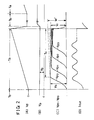
- the variable bias source 22 generates a periodic bias voltage Vb, FIG. 2(B), with the same cycle with that of the sawtooth sweep voltage V d , FIG. 2(A). It will be also noted from FIGS. 2(A) and 2(B) that the bias voltage V b has a series of ramps which are opposite in the direction of progress to those of the sawtooth voltage V d ; that is, the bias voltage V b linearly decreases with time during a time interval T a whereas the sawtooth voltage V d increases during the same time interval.
- the bias voltage V d may be so determined as to prevent potential increases in the saturation regions of the potentials V p0 -V p3 at the circuit points P0-P3, FIG. 1, as represented in FIG. 2(C) in which the scale on the vertical axis is shown exaggerated in comparison with that of FIG. 2(A).
- the peak amplitude of the bias voltage V b is therefore less than that of the sawtooth voltage V d .
- the drive voltage source 12 generates the sawtooth voltage of FIG. 2(A) in the image sensor 10 of the foregoing construction.
- the potential V p0 at the circuit point P0 of the first stage unit circuit K0 will gradually increase as shown in FIG. 2(C).
- the second diode D b0 of the unit circuit K0 will become conductive when the difference ( V p0 - V b ) between potential V p0 and bias voltage V b equals the forward voltage V f of the second diode D b0 , so that the potential V p0 will approximately level off.
- the amplitude of the sawtooth wave is shown on a reduced scale in FIG. 2(A).
- the first diode D a1 of the second stage unit circuit K1 will conductive approximately concurrently with the conduction of the second diode D b0 of the first stage unit circuit K0.
- the cathode potential of the first diode D a1 of the second stage unit circuit K1 will be approximately zero when that diode is nonconductive, and will increase in step with the sawtooth voltage V d as the sawtooth voltage increases following the conduction of the first diode D a1 .
- the voltage across thee first diode D a1 will be fixed at the forward voltage V f upon its conduction, so that the sawtooth voltage V d minus the forward voltage V f of the first diode D a1 will be applied across the second resistor R b1 .
- the potential at the point P1 of the second stage unit circuit K1 will approximately equal the voltage across the second resistor R b1 when the second diode D b1 of that unit circuit is nonconductive. Consequently, the potential V p1 at the circuit point P1 will gradually rise, as shown in FIG. 2(C), following the conduction of the first diode D a1 .
- the second diode D b1 will become conductive when the potential V P1 at the circuit point P1 minus the bias voltage V b equals the forward voltage V f of the second diode D b1 . Then the potential V p1 of the circuit point P1 will become nearly constant.
- the first diode D a2 of the third stage unit circuit K2 will become conductive approximately concurrently with the conduction of the second diode D b1 of the second stage unit circuit K1. Then the potential V p2 will develop as shown in FIG. 2(C) at the circuit point P2.
- the photodiodes S0-S3 Being connected between the circuit points P0-P3 and the ground, the photodiodes S0-S3 will be driven sequentially, that is, electrically scanned, as the potentials V p0 -V p3 at these circuit points successively build up as diagramed in FIG. 2(C).
- the image sensor 10 with the row of photodiodes S0-S3 may be put to the reading of a facsimile copy or the like.
- the sawtooth voltage of FIG. 2(A) may be applied from its source 12 to the terminal 16 while the desired optical information is being input to the photodiodes S0-S3.
- each cycle of the sawtooth voltage is composed primarily of a period T a in which the voltage rises linearly with time, and a period T b in which the voltage remains zero.
- the length of the ramp voltage period T a may be N x 2.5 microseconds, where N is the number of the first diodes D a1 , D a2 , D a3 , ... included in the image sensor.
- the ramp voltage period T a may be 25 microseconds.
- the length of the zero voltage period T b should be much longer, five milliseconds for example.
- the peak value of the sawtooth voltage V d is so determined as to cause simultaneous conduction through all of the first diodes D a0 -D a3 and the second diodes D b0 -D b3 .
- the drive voltage will be impressed to all the photodiodes S0-S3 toward the end of each ramp voltage period T a , with the consequent charging of their equivalent capacitances C s .
- the image sensor 10 may be considered to be initialized or reset when the equivalent capacitances C s of all the photodiodes S0-S3 have been charged as above.
- the equivalent capacitances C s of the photodiodes S0-S3 will be discharged during the subsequent zero voltage period T b , which is much longer than the ramp voltage period T a .
- the degree of discharge will differ from one photodiode to another depending upon the intensity of the optical information input to each photodiode during the zero voltage period T b . Of course, no discharge will take place from any photodiode whose optical input is of zero intensity.
- the optical information may be input to the photodiodes S0-S3 during other than the zero voltage periods T b of the sawtooth voltage V d .
- the periods other than the zero voltage periods T b are so much shorter that variations in charges on the photodiodes S0-S3 during such periods are negligibly small for the purposes of our invention.
- the potentials V p0 -V p3 will develop at the circuit points P0-P3 as shown in FIG. 2(C) with the linear increase in the sawtooth voltage V d during each ramp period T a .
- the photodiodes S0-S3 will be sequentially reverse biased by such potentials. In other words, the voltages for charging the equivalent capacitances C s of the photodiodes S0-S3 will be impressed to these photodiodes. At this time the charging current will flow through those of the photodiodes S0 ⁇ S3 whose equivalent capacitances C s have been discharged in the presence of optical input, but not through the other photodiodes whose equivalent capacitances have not been discharged in the absence of optical input.
- the charging currents for the equivalent capacitances C s of all the photodiodes S0-S3 will flow through the respective blocking diodes D c0 -D c3 and the common CVC circuit 14, resulting in variations in the output voltage V out obtained at the output terminal 30.
- the charge voltage for the equivalent capacitance C s of the first stage photodiode S0 varies with the potential V p0 at the circuit point P0. Therefore, should the potential V p0 increase as indicated by the broken line in FIG. 2(C), the charge voltage for the equivalent capacitance C s of the photodiode S0 would vary correspondingly, eventually rising to V r '. This charge voltage V r ' would be higher than the value V s of the potential V p0 at the start of its saturation period T c .
- the charge voltage V r ' would be the initial value of the zero voltage period T b of the sawtooth voltage V d in which the equivalent capacitance C s was to be discharged by the optical input to the photodiode S0.
- the optical input to the photodiode S0 was of extremely low intensity during the zero voltage period T b
- the resulting increase in the charge voltage for the equivalent capacitance C s might be so small at the end of the zero voltage period T b that the voltage of the equivalent capacitance C s might not become lower than the potential V s at the start of the saturation period T c .
- the prior art image sensor not having the variable bias source 22, has another shortcoming, namely, the unequal responses of the individual photodiodes to optical inputs, especially when the inputs are of low intensity.
- the solid line in FIG. 3(B) represents the response of the image sensor 10 according to our invention to the low intensity optical information.
- the broken line in the same diagram represents the response of the prior art image sensor, not having the variable bias source 22, to the low intensity optical information. It will be observed that the individual photodiodes of the prior art image sensor respond unequally to the optical inputs of the same low intensity.
- variable bias source 22 This variable bias source generates the bias voltage V b which linearly decreases with time as shown in FIG. 2(B).
- the voltages across the second diodes D b0 -D b3 are opposite in polarity to the bias voltage V b , so that the potentials V p0 -V p3 . at the circuit points P0-P3 are equal to the voltages across the second diodes D b0 -D b3 minus the bias voltage V b .
- FIG. 2 An inspection of FIG. 2 will also reveal that the periods of time during which the bias voltage V b acts effectively on the second diodes D b0 -D b3 become progressively shorter in the order of D b0 , D b1 , D b2 and D b3 .
- the periods of conduction of the second diodes D b0 -D b3 during the ramp period T a of the sawtooth voltage V d also become progressively shorter in the same order. It will therefore be appreciated that the bias voltage V b can ideally cancel undesired rises of the saturation voltages of the second diodes D b0 -D b3 , thereby eliminating fluctuations in the sensitivity of the individual photodiodes S0-S3.
- FIG. 5 a more practical form of image sensor 110 according to our invention which is suitable for use with facsimile.
- the image sensor 110 comprises a plurality or multiplicity of groups of photoelectric unit circuits B1-B n of the same construction as the unit circuits K0-K3 of the FIG. 1 image sensor 10.
- FIG. 5 system As a one dimensional image sensor there may be provided as many as 2000 photodiodes in a row. These photodiodes may be divided into from several to several hundreds groups.
- Two sawtooth generator circuits 112 and 112' are provided for driving the unit circuit groups B1-B n . Under the control of a timing circuit 140 the sawtooth generator circuits 112 and 112' generates respectively the sawtooth voltages V1 and V2 shown at (A) and (B) in FIG. 6.
- each cycle T of the sawtooth voltage V1 generated by the first sawtooth generator circuit 112 is composed of a ramp period t1-t2, a brief return period t2-t3, and a zero period t3-t5.
- the first sawtooth generator circuit 112 generates a series of triangular pulses, another pulse being generated between t5-t9.
- the sawtooth voltage V2 generated by the second sawtooth generator circuit 112' is also comprised of a similar series of triangular pulses, but with a phase lag T d from the first sawtooth voltage V1. More specifically, in this particular embodiment, the ramp periods t2-t5 and t5-t10 of the second sawtooth voltage V2 start at the ends of, and end at the beginnings of, the ramp periods t1-t2 and t5-t8 of the first sawtooth voltage V1 .
- the first sawtooth generator circuit 112 is connected via a first demultiplexor 142 to the supply terminals 144 of the odd numbered ones B1, B3, ...B n-1 of the unit circuit groups B1 - B n .
- the timing circuit 140 also connected to the first demultiplexor 142, causes the same to deliver one cycle t1-t5 of the first sawtooth voltage V1 to the first unit circuit group B1, the next cycle t5-t10 of the first sawtooth voltage to the third unit circuit group B3, and so forth.
- the second sawtooth generator circuit 112' is likewise connected via a second demultiplexor 142' to the supply terminals 144' of the even numbered ones B2, B3, ...B n of the ,unit circuit groups B1-B n .
- the second demultiplexor 142' delivers one cycle t2-t8 of the second sawtooth voltage V2 to the second unit circuit group B2, the next cycle t8- of the second sawtooth voltage to the fourth unit circuit group B4, and so forth.
- the first demultiplexor 142 may be controlled to derive only the ramp periods t1-t2, t8-t s , etc., from the first sawtooth voltage V1 for delivery to the successive odd numbered unit circuit groups B1, B3, ...B n-1 .
- the second demultiplexor 142' may be controlled to derive only the ramp periods t2-t5, t8-t10, etc., from the second sawtooth voltage V2 for delivery to the successive even numbered unit circuit groups B2, B4, ...B n .
- ground terminals of the unit circuit groups B1-B n are functionally equivalent to the grounded sawtooth supply terminal 18 of the FIG. 1 image sensor 10.
- the odd numbered unit circuit groups B1, B3, ...B n-1 are connected to a first CVC circuit 114 by way of individual output lines 124 and a common output line 146.
- the even numbered unit circuit groups B2, B4, ...B n are connected to a second CVC circuit 114' by way of individual output lines 124' and a common output line 146'.
- the first CVC circuit 114 comprises an operational amplifier 126 and a feedback resistor R f .
- the operational amplifier 126 has its inverting input connected to the common output line 146 of the odd numbered unit circuit groups B1, B3, ...B n-1 , besides being connected to the feedback resistor R f .
- the noninverting input of the operational amplifier 126 is grounded.
- the second CVC circuit 114' is of like construction, comprising an operational amplifier 126' and a feedback resistor R f '.
- the operational amplifier 126' has its inverting input connected to the common output line 146' of the even numbered unit circuit groups B2, B4, ...B n , besides being connected to the feedback resistor R f '.
- the noninverting input of the operational amplifier 126' is grounded.
- the first and second CVC circuits 114 and 114' are connected via respective inverting amplifiers 128 and 128' to another multiplexor 148 and thence to an output terminal 130.
- the additional multiplexor 148 is thereby controlled to combine the outputs V a and V b , FIGS. 6(E) and 6(F), from the inverting amplifiers 128 and 128' into the image sensor output V out , FIG. 6(G), at the ⁇ erminal 130.
- the first variable bias source 122 is connected to the common bias terminals 120 of the odd numbered unit circuit groups B1, B3, ...B n-1 whereas the second variable bias source 122' is connected to the common bias terminals 120' of the even numbered unit circuit groups B2, B4, ...B n .
- the first and second variable bias sources 122 and 122' generate respectively the first and second periodic bias voltages V b1 and V b2 , FIGS. 6(C) and 6(D), under the control of the timing circuit 140.
- the unit circuit groups B1-B n comprises pin diodes such as shown at D a1 -D a3 , D b1 -D b3 and D c1 -D c3 .
- the equivalent capacitances of these pin diodes are charged during the application of the sawtooth voltage.
- the current flow through the output lines 124 and 124' will be reversed, with the consequent development of reverse voltages as indicated in FIGS. 6(E) and 6(F).
- Such reverse voltages are undesirable in combining the outputs from the unit circuit groups B1-B n . We have practically eliminated the adverse effects of such reverse voltages by dividing the unit circuit groups into the odd and even numbered ones.
- the first and second demultiplexors 142 and 142' will deliver the successive cycles of the first and second sawtooth voltages V1 and V2 to the successive odd numbered photoelectric unit circuit groups B1, B3, ... B n-1 and to the successive even numbered photoelectric unit circuit groups B2, B4, ... B n , respectively.
- the output voltage V a from the first inverting amplifier 128 will first vary as during the t1-t2 is interval in FIG. 6(E) and then go negative during the subsequent t2-t4 interval Te.
- this reverse voltage will not affect the reading of the desired optical information by the next odd numbered unit circuit group B3.
- the moment t4 in FIG. 6 may be defined as follows: If the image sensor is designed to discriminate N intensities of optical input from one another, then the moment t4 is the moment the reverse voltage becomes less than 1/N of the difference (e.g. 1000 nA) between the amplitude of each output voltage V a or V b when the optical input is of the maximum intensity and the amplitude when the optical input is cut off.
- 1/N of the difference e.g. 1000 nA
- the scanning of the odd and even numbered unit circuit groups B1-B n takes place alternately.
- the odd numbered unit circuit groups B1, B3, ... B n-1 are not being scanned by the first sawtooth voltage V1, FIG. 6(A)
- the even numbered unit circuit groups B2, B4, ... B n will be scanned by the second sawtooth voltage V2, FIG. 6(B).
- the second output voltage V b , FIG. 6(F) will thus be obtained on the output side of the second inverting amplifier 128'.
- the voltages V a and V b will be both directed into the multiplexor 148, thereby to be combined into the single output voltage V out shown in FIG. 6(G). It will be noted from FIGS. 6(E)-6(G) that the multiplexor 148 extracts only the periods t1-t2, t5-t8, etc., from the first input voltage V a , and only the periods t2-t5 t8-t10 , etc., from the second input voltage V b , thereby eliminating the reverse voltage components of these input voltages.
- the electric signals from the photodiodes included in all the unit circuit groups B1-B n can thus be accurately and quickly combined into the signal output voltage V out of the image sensor 110 which represents the optical information incident on all the photodiodes included in the unit circuit groups.
- the multiplexor 148 represents but one of several possible means for, combining the voltages V a and V b into the image sensor output voltage V out .
- diodes may be connected between the outputs of the operational amplifiers 126 and 126' and the ground for absorbing the reverse components of the voltages V a and V b , and an adder circuit may be substituted for the multiplexor 148.
Landscapes
- Engineering & Computer Science (AREA)
- Multimedia (AREA)
- Signal Processing (AREA)
- Transforming Light Signals Into Electric Signals (AREA)
- Facsimile Heads (AREA)
- Solid State Image Pick-Up Elements (AREA)
- Facsimile Scanning Arrangements (AREA)
Applications Claiming Priority (2)
| Application Number | Priority Date | Filing Date | Title |
|---|---|---|---|
| JP2086729A JPH0691603B2 (ja) | 1990-03-30 | 1990-03-30 | イメージセンサ |
| JP86729/90 | 1990-03-30 |
Publications (2)
| Publication Number | Publication Date |
|---|---|
| EP0449098A2 true EP0449098A2 (fr) | 1991-10-02 |
| EP0449098A3 EP0449098A3 (en) | 1992-07-15 |
Family
ID=13894940
Family Applications (1)
| Application Number | Title | Priority Date | Filing Date |
|---|---|---|---|
| EP19910104368 Withdrawn EP0449098A3 (en) | 1990-03-30 | 1991-03-20 | Image sensor having photodiodes of improved response to low intensity optical input |
Country Status (4)
| Country | Link |
|---|---|
| US (1) | US5093727A (fr) |
| EP (1) | EP0449098A3 (fr) |
| JP (1) | JPH0691603B2 (fr) |
| KR (2) | KR940000709B1 (fr) |
Cited By (1)
| Publication number | Priority date | Publication date | Assignee | Title |
|---|---|---|---|---|
| CN110944130A (zh) * | 2018-09-21 | 2020-03-31 | 爱思开海力士有限公司 | 斜坡信号发生器和包括该斜坡信号发生器的图像传感器 |
Families Citing this family (4)
| Publication number | Priority date | Publication date | Assignee | Title |
|---|---|---|---|---|
| JP3018492B2 (ja) * | 1990-11-28 | 2000-03-13 | ソニー株式会社 | 固体撮像素子の露光調整装置 |
| JPH05110056A (ja) * | 1991-10-15 | 1993-04-30 | Fuji Xerox Co Ltd | イメージセンサ |
| US5335015A (en) * | 1992-10-30 | 1994-08-02 | Texas Instruments Incorporated | Method for improved dynamic range of BCMD image sensors |
| US5774180A (en) * | 1992-12-04 | 1998-06-30 | Fuji Xerox Co., Ltd. | Image sensor capable of producing an image signal free from an afterimage |
Family Cites Families (6)
| Publication number | Priority date | Publication date | Assignee | Title |
|---|---|---|---|---|
| US3432670A (en) * | 1964-12-28 | 1969-03-11 | Ibm | Radiation scanner employing constant current means |
| US3418652A (en) * | 1965-09-13 | 1968-12-24 | Brooks William | Programming device and sawtooth generator therefor |
| US3448275A (en) * | 1967-06-07 | 1969-06-03 | Ibm | Electro-optical scanner with a photocell and a blocking diode in series |
| DE3112907A1 (de) * | 1980-03-31 | 1982-01-07 | Canon K.K., Tokyo | "fotoelektrischer festkoerper-umsetzer" |
| US4785191A (en) * | 1987-04-17 | 1988-11-15 | Stemcor Corporation | Interconnected array of photosensors for simultaneously sensing light intensities at each of a number of locations |
| EP0386254A4 (en) * | 1988-07-30 | 1992-08-12 | Taiyo Yuden Co., Ltd. | Scanning circuit device |
-
1990
- 1990-03-30 JP JP2086729A patent/JPH0691603B2/ja not_active Expired - Lifetime
-
1991
- 1991-03-15 US US07/669,926 patent/US5093727A/en not_active Expired - Fee Related
- 1991-03-20 EP EP19910104368 patent/EP0449098A3/en not_active Withdrawn
- 1991-03-29 KR KR1019910004981A patent/KR940000709B1/ko not_active Expired - Fee Related
- 1991-06-25 KR KR1019910010526A patent/KR940000710B1/ko not_active Expired - Fee Related
Cited By (2)
| Publication number | Priority date | Publication date | Assignee | Title |
|---|---|---|---|---|
| CN110944130A (zh) * | 2018-09-21 | 2020-03-31 | 爱思开海力士有限公司 | 斜坡信号发生器和包括该斜坡信号发生器的图像传感器 |
| CN110944130B (zh) * | 2018-09-21 | 2021-12-03 | 爱思开海力士有限公司 | 斜坡信号发生器和包括该斜坡信号发生器的图像传感器 |
Also Published As
| Publication number | Publication date |
|---|---|
| KR940000710B1 (ko) | 1994-01-27 |
| JPH0691603B2 (ja) | 1994-11-14 |
| KR940000709B1 (ko) | 1994-01-27 |
| EP0449098A3 (en) | 1992-07-15 |
| US5093727A (en) | 1992-03-03 |
| JPH03285451A (ja) | 1991-12-16 |
| KR910017826A (ko) | 1991-11-05 |
Similar Documents
| Publication | Publication Date | Title |
|---|---|---|
| US5479208A (en) | Image sensors and driving method thereof | |
| US4556800A (en) | Optical image sensor apparatus with grouped photosensors connected in common | |
| US5146074A (en) | Solid state imaging device | |
| EP0449098A2 (fr) | Capteur d'images ayant des photodiodes avec une sensibilité accrue pour une lumière de faible intensité | |
| US4585934A (en) | Self-calibration technique for charge-coupled device imagers | |
| US4634886A (en) | Photoelectric imager with a high S/N ratio | |
| JPH04168876A (ja) | 積分器及び画像読取装置 | |
| US5856666A (en) | Multiplexer circuit | |
| US5249055A (en) | Solid-state imaging apparatus including external charge input terminal | |
| US5006702A (en) | Scanning circuit device with sawtooth voltage source | |
| KR100265139B1 (ko) | 광센서 수단에 빛이 조사되는 빈도를 감지하는 광센서 수단 | |
| JP3026288B2 (ja) | イメージセンサ | |
| US4926205A (en) | Phase-difference detector | |
| SU1596359A1 (ru) | Устройство дл считывани изображений | |
| JPH0142186B2 (fr) | ||
| JPH03209767A (ja) | イメージセンサ | |
| JP2514486B2 (ja) | イメ−ジセンサ | |
| JPH0473969A (ja) | イメージセンサ | |
| JPS6156572A (ja) | イメ−ジセンサ駆動回路 | |
| JPS61148956A (ja) | 光電変換装置 | |
| JPH0576220B2 (fr) | ||
| JPH04355563A (ja) | イメ−ジセンサの読取回路 | |
| JPH0444461A (ja) | イメージセンサ | |
| JPH0316464A (ja) | 固体撮像装置の駆動方法 | |
| JPH05227363A (ja) | イメージセンサ及びその読み取り方法及び画像読取装置 |
Legal Events
| Date | Code | Title | Description |
|---|---|---|---|
| PUAI | Public reference made under article 153(3) epc to a published international application that has entered the european phase |
Free format text: ORIGINAL CODE: 0009012 |
|
| AK | Designated contracting states |
Kind code of ref document: A2 Designated state(s): DE FR GB |
|
| PUAL | Search report despatched |
Free format text: ORIGINAL CODE: 0009013 |
|
| AK | Designated contracting states |
Kind code of ref document: A3 Designated state(s): DE FR GB |
|
| STAA | Information on the status of an ep patent application or granted ep patent |
Free format text: STATUS: THE APPLICATION IS DEEMED TO BE WITHDRAWN |
|
| 18D | Application deemed to be withdrawn |
Effective date: 19930118 |