EP0449199A2 - Rauschreduktionsschaltung - Google Patents
Rauschreduktionsschaltung Download PDFInfo
- Publication number
- EP0449199A2 EP0449199A2 EP91104752A EP91104752A EP0449199A2 EP 0449199 A2 EP0449199 A2 EP 0449199A2 EP 91104752 A EP91104752 A EP 91104752A EP 91104752 A EP91104752 A EP 91104752A EP 0449199 A2 EP0449199 A2 EP 0449199A2
- Authority
- EP
- European Patent Office
- Prior art keywords
- noise
- circuit
- signal
- output
- inference
- Prior art date
- Legal status (The legal status is an assumption and is not a legal conclusion. Google has not performed a legal analysis and makes no representation as to the accuracy of the status listed.)
- Granted
Links
- 230000001603 reducing effect Effects 0.000 title claims abstract description 19
- 230000002238 attenuated effect Effects 0.000 claims abstract description 6
- 238000000034 method Methods 0.000 description 11
- 230000007423 decrease Effects 0.000 description 8
- 239000002131 composite material Substances 0.000 description 7
- 238000010586 diagram Methods 0.000 description 7
- 238000000926 separation method Methods 0.000 description 6
- 238000010276 construction Methods 0.000 description 4
- 230000000694 effects Effects 0.000 description 4
- 230000005236 sound signal Effects 0.000 description 4
- 239000003990 capacitor Substances 0.000 description 3
- 230000003247 decreasing effect Effects 0.000 description 3
- 230000001747 exhibiting effect Effects 0.000 description 1
- 239000004065 semiconductor Substances 0.000 description 1
- 230000002194 synthesizing effect Effects 0.000 description 1
Images


Classifications
-
- H—ELECTRICITY
- H04—ELECTRIC COMMUNICATION TECHNIQUE
- H04B—TRANSMISSION
- H04B1/00—Details of transmission systems, not covered by a single one of groups H04B3/00 - H04B13/00; Details of transmission systems not characterised by the medium used for transmission
- H04B1/06—Receivers
- H04B1/16—Circuits
- H04B1/1646—Circuits adapted for the reception of stereophonic signals
- H04B1/1661—Reduction of noise by manipulation of the baseband composite stereophonic signal or the decoded left and right channels
-
- H—ELECTRICITY
- H04—ELECTRIC COMMUNICATION TECHNIQUE
- H04B—TRANSMISSION
- H04B1/00—Details of transmission systems, not covered by a single one of groups H04B3/00 - H04B13/00; Details of transmission systems not characterised by the medium used for transmission
- H04B1/06—Receivers
- H04B1/10—Means associated with receiver for limiting or suppressing noise or interference
- H04B1/1027—Means associated with receiver for limiting or suppressing noise or interference assessing signal quality or detecting noise/interference for the received signal
-
- Y—GENERAL TAGGING OF NEW TECHNOLOGICAL DEVELOPMENTS; GENERAL TAGGING OF CROSS-SECTIONAL TECHNOLOGIES SPANNING OVER SEVERAL SECTIONS OF THE IPC; TECHNICAL SUBJECTS COVERED BY FORMER USPC CROSS-REFERENCE ART COLLECTIONS [XRACs] AND DIGESTS
- Y10—TECHNICAL SUBJECTS COVERED BY FORMER USPC
- Y10S—TECHNICAL SUBJECTS COVERED BY FORMER USPC CROSS-REFERENCE ART COLLECTIONS [XRACs] AND DIGESTS
- Y10S706/00—Data processing: artificial intelligence
- Y10S706/90—Fuzzy logic
Definitions
- the present invention relates to a noise reducing circuit in which various kinds of noises contained in the demodulated output of a radio receiver is reduced by the use of fuzzy control.
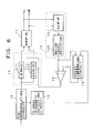
- FIG. 1 shows one such noise reducing circuit using a feedback control.
- a noise reducing circuit 20 includes a noise attenuating circuit 21, a noise level detecting circuit 22, and a control signal generating circuit 23.
- the noise attenuating circuit 21 takes the form of, for example, a frequency-characteristic controlling circuit, stereo-separation controlling circuit, muting control circuit, or a combination of these.
- the noise detecting circuit 22 detects a noise level in the output of the noise attenuating circuit 21 to output a noise-level signal.
- the control signal generating circuit 23 compares the noise-level signal with a fixed reference voltage Vs so as to output a control signal whose magnitude is proportional to the difference between the noise-level signal and the reference voltage Vs. The control signal is fed back to the noise attenuating circuit 21.
- the feedback control effectively reduces the noise in the receiver output.
- a noise reducing circuit in an FM receiver such as the above-described frequency characteristic controlling circuit, stereo-separation controlling circuit, and muting control circuit has only a narrow range of control, e.g., about 20 dB for the stereo-separation controlling circuit and about several decibels for the frequency characteristic controlling circuit. This does not allow sufficient noise-reducing effect over a wide range of field intensity.
- An object of the present invention is to provide a noise reducing circuit in which the degree of noise reduction effect on the receiver output is controlled over a wide range of field intensity of an input to the receiver by the use of fuzzy control technique.
- a noise attenuating circuit receives a demodulated signal and attenuates the noise in the demodulated signal in accordance with a control signal supplied thereto.
- a signal strength detecting circuit outputs a field intensity signal indicative of the strength of an radio wave signal inputted to the receiver.
- An output noise level detecting circuit outputs a noise level signal indicative of a noise level in the demodulated signal after the noise is attenuated.
- a fuzzy inferring circuit performs fuzzy inference in accordance with fuzzy production rules given by membership functions for the field intensity signal E and for the noise level signal N, respectively, so as to output an inference output .
- a control signal generating circuit produces the control signal on the basis of the inference output to control the noise attenuating circuit.
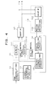
- Fig. 4 shows the construction of a first embodiment of the invention.
- the composite signal of an FM stereo signal demodulated by an FM demodulating circuit 16 is supplied to the noise attenuating circuit 11, which in turn sends the composite signal whose noise is attenuated to an MPX demodulating circuit 17.
- the noise attenuating circuit 11 consists of two circuits; one is a stereo noise control circuit 111(referred to as SNC hereinafter) where the level of the sub channel component(L-R) in the composite signal is attenuated in accordance with an SNC control signal supplied thereto, the other is a high-cut control circuit 112(referred to as HCC hereinafter) where the main channel component(L+R) is reduced a signal level thereof at higher frequencies in accordance with an HCC control signal supplied thereto.
- the composite signal from the noise attenuating circuit 11 is then separated by the MPX demodulating circuit 17 into the left and right audio signals.
- a noise level detecting circuit 13 includes a high-pass filter 131 and a noise level detector 132.
- the high-pass filter 131 passes high frequency component, i.e., noise component over about 20 kHz in the left and right audio signals.
- the noise level detector 132 rectifies the output of the high-pass filter 131 to produce a noise level signal and supplies it to a fuzzy inferring circuit 14.
- the signal strength detecting circuit 12 rectifies the intermediate frequency signal in the FM demodulating circuit 16 to produce a field strength signal indicative of the field intensity E, and supplies it to the fuzzy inferring circuit 14.
- the fuzzy inferring circuit 14 receives the field intensity signal E and the noise level signal N to perform fuzzy inference processing on the field intensity signal E and the noise level signal N in accordance with fuzzy production rules given by membership functions for these signals E and N, respectively. The fuzzy inference processing will be described later.
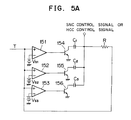
- the control signal generating circuit 15 receives the output T of the circuit 14 to produce the SNC control signal and HCC control signal and then supplies these control signals to the SNC circuit 111 and the HCC circuit 112, respectively.
- the output T of the fuzzy inferring circuit 14 is supplied to comparators 151-153 which compare the output T with reference voltages Vs1 to Vs3 which are in the relationship of Vs1 ⁇ Vs2 ⁇ Vs3.
- the output T of the fuzzy inferring circuit 14 is also supplied to a resistor R which forms various time constants together with capacitors C1-C3.
- Vs2>T>Vs1 the transistor 154 turns on forming a time constant RC1.
- Vs3>T>Vs2 the transistors 154 and 155 turn on forming a time constant R(C1+C2).
- T>Vs3 the transistors 154, 155, 156 turn on forming a time constant R(C1+C2+C3).
- the capacitors C1-C3 are such that they are in the relationship of RC1 ⁇ R(C1+C2) ⁇ R(C1+C2+C3). Therefore, the output of the control signal generating circuit 15 slowly varies from a previous value of T to a new value of T with one of the time constants RC1, R(C1+C2), and R(C1+C2+C3).
- Fig. 5B shows another example of the control signal generating circuit 15 in the form of a subtracter.
- the output T of the fuzzy inferring circuit 14 is also supplied to a series-circuit of resistors R1, R2, and R3 which form various time constants together with a capacitor C.
- the outputs of the comparators 151-153 are fed to the control terminals of an analog switch 157 via inverters 158-160.
- Each of switch elements 157a-157c of the analog switch 157 is connected in parallel with the resistors R1-R3.
- the analog switch 157 is available from various semiconductor manufactures. When Vs2>T>Vs1, the switch element 157c opens forming a time constant R1C.
- the switch element 157c and 157b open forming a time constant C(R1+R2).
- the switch element 157a, 157b, 157c open forming a time constant C(R1+R2+R3).
- the resistors R1-R3 are such that they are in the relation of CR1 ⁇ C(R1+R2) ⁇ C(R1+R2+R3). Therefore, the output of the control signal generating circuit 15 slowly varies from a previous value of T to a new value of T with one of the time constants CR1, C(R1+R2), and C(R1+R2+R3).
- the noise contained in the audio output of the receiver is reduced by a feedback loop using the fuzzy control technique.
- the fuzzy control technique used in the invention consists of fuzzy production rules R1 and R2, which are given by membership functions (mA1, mA2, mB1, mB2) set theoretically or experimentally so that best possible quality of receiver output is achieved in accordance with the field intensity E of an input to the receiver and the noise level N contained in the audio output of the receiver.
- the fuzzy production rule R1 is as follows:
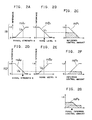
- Fig. 2A shows the plot of the membership function mA1 that gives the idea of how high the field intensity E is.
- the abscissa represents the field intensity E and the ordinate indicates the grade of inference that matches the antecedent a1. If an actual field intensity E is adequately high so that it can be said that the field intensity is absolutely "high,” then the grade of inference is 1. If an actual field intensity E is adequately low so that it can be said that the field intensity is absolutely "low,” then the grade of inference is 0.
- the curve in Fig. 2A indicates that the grade of inference increases as the field intensity E increases.
- Fig. 2B shows the plot of the membership function mB1 that gives the idea of how low the noise level N is.
- the abscissa represents the noise level N and the ordinate indicates the grade of inference that matches the antecedent b1. If an actual noise level N is adequately low so that it can be said that the noise level is absolutely "low,” then the grade of inference is 1. If an actual noise level N is adequately high so that it can be said that the noise level is absolutely "high,” then the grade of inference is 0.
- the curve in Fig. 2B indicates that the grade of inference decreases as the noise level N increases.
- Fig. 2C shows the plot of the membership function mP1 that gives the inference conclusion.
- the abscissa represents the reference voltage Vr in the fuzzy inferring circuit 14 and the ordinate indicates the grade of inference that matches the consequent of rule R1. If an actual inference conclusion is adequately close to the consequent of rule R1 so that it can be said that the inference conclusion completely coincides with the consequent, then the grade of inference is 1. If an actual inference conclusion is adequately far from the consequent of the production rule R1 so that it can be said that the inference conclusion is absolutely far from the consequent of rule R1, then the grade of inference is 0.
- the curve in Fig. 2C indicates that the grade of inference conclusion decreases as the reference voltage Vr in the fuzzy inferring circuit 14 decreases.
- the fuzzy production rule R2 is as follows:
- Fig. 2D shows the plot of the membership function mA2 that gives the idea of how low the field intensity E is.
- the abscissa represents the field intensity E and the ordinate indicates the grade of inference that matches the antecedent a2. If an actual field intensity E is adequately low so that it can be said that the field intensity E is absolutely "low,” then the grade of inference is 1. If an actual field intensity E is adequately high so that it can be said that the field intensity is absolutely "high,” then the grade of inference is 0.
- the curve in Fig. 2D indicates that the grade of inference decreases as the field intensity E increases.
- Fig. 2E shows the plot of the membership function mB2 that gives the idea of how high the noise level N is.
- the abscissa represents the noise level N and the ordinate indicates the grade of inference that matches the antecedent b2. If an actual noise level N is adequately high so that it can be said that the noise level is absolutely "high,” then the grade of inference is 1. If an actual noise level N is adequately low so that it can be said that the noise level is absolutely "low,” then the grade of inference is 0.
- the curve in Fig. 2E indicates that the grade of inference increases as the noise level N increases.
- Fig. 2F shows the plot of the membership function mP2 that gives the inference conclusion.
- the abscissa represents the reference voltage Vr in the fuzzy inferring circuit 14 and the ordinate indicates the grade of inference that matches the consequent of rule R2. If an actual inference conclusion is adequately close to the consequent of rule R2 so that it can be said that the inference conclusion completely coincides with the consequent, then the grade of inference is 1. If an actual inference conclusion is adequately far from the consequent of rule R2 so that it can be said that the inference conclusion is absolutely far from the consequent of rule R2, then the grade of inference is 0. The curve in Fig. 2F indicates that the grade of inference conclusion increases as the reference voltage Vr in the fuzzy inferring circuit 14 increases.
- a feedback loop should be of a negative feedback in order that the feedback loop is stable at all times. If the loop becomes a positive feedback loop, then the loop becomes unstable.
- the respective elements(11-13, 15-17) of the present invention in Fig. 4 have a linear input-to-output relationship and are known to be stable at any conditions. Thus, the stability of the fuzzy inferring circuit 14 determines the stability of the entire loop.
- C f(E, N) where C is an amount of control, E is the field intensity of the signal to the receiver, N is the noise level, and f is a function.
- the fuzzy inference processing of the present invention is carried out as follows:
- the control signal generating circuit 15 provides the SNC control signal as well as HCC control signal on the basis of the final inference conclusion.
- the control signal generating circuit 15 may be designed such that it provides various control signals based on the fuzzy inference. For example, the control signal may be outputted when it exceeds a predetermined threshold level above which the noise attenuating circuit is under fuzzy control, or may be outputted with a time constant during which the noise attenuating circuit shifts from one operating point to another as in the first embodiment.
- control signal decreases in magnitude with increasing field intensity E or decreasing noise level N, while the noise attenuating circuit 11 carries out the noise-attenuating operation designed for lower noise levels N.
- control signal increases in magnitude with decreasing field intensity E or increasing noise level N, and the noise attenuating circuit 11 carries out the noise-attenuating operation designed for higher noise levels N.
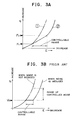
- Fig. 3A shows the noise characteristics of a noise reducing circuit using a feedback loop with fuzzy control therein.
- Fig. 3B shows the noise characteristics of a prior art noise reducing circuit in Fig. 1.
- the abscissa represents the field intensity E and the ordinate the noise level N.
- Curve 1 shows a noise characteristic without fuzzy control and curve 2 with fuzzy control. As the receiving condition becomes worse, the final inference conclusion shifts from F1 to F2. Thus, as compared to the prior art noise reducing circuit, the noise characteristic has a slower change exhibiting noise reducing effect over a wider range of field intensity of the signal to the receiver.
- noise reduction is effected by attenuating or processing part of the demodulated output resulting in a loss in fidelity to some extent.
- the SNC circuit 111 in Fig. 4 attenuates the level of sub channel component of the stereo composite signal in accordance with the SNC control signal supplied thereto so as to reduce noise level.
- attenuating the sub channel component causes the stereo separation characteristic to be deteriorated. Therefore, noise reduction effect and the overall signal quality of the receiver output are two opposing factors.
- the degree of attenuating or processing part of the demodulated signal is varied in accordance with the noise level N and the field intensity E so that the noise in the receiver output is reduced with a minimum loss of fidelity.
- Fig. 6 shows a second embodiment of the invention.
- the control signal generating circuit 15 produces an SNC/HCC control signal on the basis of the noise level N and the output of the fuzzy inferring circuit 14 so as to control the SNC circuit 111 and the HCC circuit 112.
- the threshold level of control operation of the SNC 111 is set lower than that of the HCC circuit 112.
- the HCC circuit 112 When the SNC/HCC control signal exceeds the predetermined level, the HCC circuit 112 now starts to operate so as to take out the main signal (L+R) in the composite signal to reduce the signal level at higher frequencies of the main signal. That is, the lower the field intensity E becomes, the more the HCC circuit 112 attenuates the signal level at higher frequencies of the main signal. This causes the noise level contained in the L and R channel audio signals to decrease.
- control signal generating circuit 15 produces the SNC/HCC control signal on the basis of the output of the fuzzy inferring circuit 14 and the noise-level signal N
- the circuit can also be arranged such that the control signal generating circuit 15 is supplied with the field intensity signal E instead of the noise-level signal N.
Landscapes
- Engineering & Computer Science (AREA)
- Computer Networks & Wireless Communication (AREA)
- Signal Processing (AREA)
- Feedback Control In General (AREA)
- Stereo-Broadcasting Methods (AREA)
- Noise Elimination (AREA)
Applications Claiming Priority (4)
| Application Number | Priority Date | Filing Date | Title |
|---|---|---|---|
| JP76739/90 | 1990-03-28 | ||
| JP7673990A JPH03278621A (ja) | 1990-03-28 | 1990-03-28 | ノイズ低減回路 |
| JP7673890A JPH03278620A (ja) | 1990-03-28 | 1990-03-28 | ノイズ低減回路 |
| JP76738/90 | 1990-03-28 |
Publications (3)
| Publication Number | Publication Date |
|---|---|
| EP0449199A2 true EP0449199A2 (de) | 1991-10-02 |
| EP0449199A3 EP0449199A3 (en) | 1992-08-19 |
| EP0449199B1 EP0449199B1 (de) | 1995-07-05 |
Family
ID=26417873
Family Applications (1)
| Application Number | Title | Priority Date | Filing Date |
|---|---|---|---|
| EP91104752A Expired - Lifetime EP0449199B1 (de) | 1990-03-28 | 1991-03-26 | Rauschreduktionsschaltung |
Country Status (3)
| Country | Link |
|---|---|
| US (1) | US5201062A (de) |
| EP (1) | EP0449199B1 (de) |
| DE (1) | DE69110934T2 (de) |
Cited By (12)
| Publication number | Priority date | Publication date | Assignee | Title |
|---|---|---|---|---|
| EP0560599A1 (de) * | 1992-03-11 | 1993-09-15 | Matsushita Electric Industrial Co., Ltd. | Gerät zur Rauschunterdrückung |
| WO1994022232A1 (de) * | 1993-03-24 | 1994-09-29 | Blaupunkt-Werke Gmbh | Rundfunkempfänger mit digitaler signalverarbeitung |
| WO1994022229A1 (de) * | 1993-03-24 | 1994-09-29 | Blaupunkt-Werke Gmbh | Schaltungsanordnung zur ableitung von signalen zur maskierung von audiosignalen |
| WO1994022231A1 (de) * | 1993-03-24 | 1994-09-29 | Blaupunkt-Werke Gmbh | Rundfunkempfänger mit digitaler signalverarbeitung |
| US5396657A (en) * | 1991-11-14 | 1995-03-07 | Nokia Mobile Phones Ltd. | Selectable filter for reducing Gaussian noise, co-channel and adjacent channel interference in a radio-telephone receiver |
| US5430894A (en) * | 1992-03-11 | 1995-07-04 | Matsushita Electric Industrial Co., Ltd. | Radio receiver noise suppression system |
| EP0653850A3 (de) * | 1993-11-12 | 1995-11-29 | Blaupunkt Werke Gmbh | Schaltungsanordnung zur Erkennung von Nachbarkanalstörungen. |
| WO2000077939A1 (en) * | 1999-06-16 | 2000-12-21 | Koninklijke Philips Electronics N.V. | Fm receiver with bandwidth control means |
| WO2002054608A1 (en) * | 2000-12-28 | 2002-07-11 | Hi-Key Limited | A radio receiver |
| EP0881779A3 (de) * | 1997-05-28 | 2003-04-23 | Grundig Car InterMedia System GmbH | Verfahren zur Erkennung von Multipathstörungen beim FM-Rundfunkempfang und Schaltungsanordnung zur Durchführung des Verfahrens |
| EP0911986A3 (de) * | 1997-10-22 | 2003-04-23 | Grundig Car InterMedia System GmbH | Verfahren zur Erkennung von Multipathstörungen und Schaltungsanordnung zur Durchführung des Verfahrens |
| EP1120919A3 (de) * | 1999-12-22 | 2003-08-06 | Mitsubishi Denki Kabushiki Kaisha | Mehrwegrauschunterdrücker , Audioausgangsschaltung und FM-Empfänger |
Families Citing this family (14)
| Publication number | Priority date | Publication date | Assignee | Title |
|---|---|---|---|---|
| US5390342A (en) * | 1990-03-14 | 1995-02-14 | Pioneer Electronic Corporation | Receiver using selective diversity receiving system |
| JP3018634B2 (ja) * | 1991-09-05 | 2000-03-13 | 日本電気株式会社 | Fm雑音低減回路 |
| US5740523A (en) * | 1993-06-30 | 1998-04-14 | Shintom Co., Ltd. | Radio receiver |
| US5371695A (en) * | 1993-10-14 | 1994-12-06 | Ford Motor Company | Method for automatically controlling the bandwidth of a digital filter and adaptive filter utilizing same |
| DE69535621T2 (de) * | 1994-09-02 | 2008-02-07 | Matsushita Electric Industrial Co., Ltd., Kadoma | Erkennungsvorrichtung zur Modulationsgrad |
| US5671286A (en) * | 1995-06-09 | 1997-09-23 | Ford Motor Company | Strategy for controlling FM stereo separation and frequency response in noisy reception environments |
| DE19542737A1 (de) * | 1995-11-16 | 1997-05-22 | Bayerische Motoren Werke Ag | Schaltanordnung für mobile Rundfunkempfänger |
| DE19707673A1 (de) * | 1997-02-26 | 1998-08-27 | Bosch Gmbh Robert | Verfahren zur Beeinflussung der Stereo-Kanaltrennung eines Audiosignals und Anordnung dazu |
| JP2000332710A (ja) * | 1999-05-24 | 2000-11-30 | Sanyo Electric Co Ltd | ステレオ放送用受信装置 |
| US6850736B2 (en) * | 2000-12-21 | 2005-02-01 | Tropian, Inc. | Method and apparatus for reception quality indication in wireless communication |
| JP2004128930A (ja) * | 2002-10-03 | 2004-04-22 | Toyota Industries Corp | Fm受信機、fm受信機のノイズ除去装置及びノイズ除去方法 |
| JP4263123B2 (ja) * | 2004-03-23 | 2009-05-13 | 三洋電機株式会社 | 信号処理回路 |
| US7697908B2 (en) * | 2006-04-13 | 2010-04-13 | Mediatek Inc. | Duty-to-voltage amplifier, FM receiver and method for amplifying a peak of a multiplexed signal |
| US11018783B2 (en) * | 2019-07-12 | 2021-05-25 | Eagle Technology, Llc | System and method for mitigating broadband interference |
Family Cites Families (12)
| Publication number | Priority date | Publication date | Assignee | Title |
|---|---|---|---|---|
| US3851253A (en) * | 1973-05-25 | 1974-11-26 | Motorola Inc | Automatically adjustable fm receiver squelch |
| SE436491B (sv) * | 1982-06-22 | 1984-12-17 | Frigoscandia Contracting Ab | Anordning for luftbehandling av produkter |
| JPS61263327A (ja) * | 1985-05-17 | 1986-11-21 | Pioneer Electronic Corp | 音声多重受信機 |
| US4628529A (en) * | 1985-07-01 | 1986-12-09 | Motorola, Inc. | Noise suppression system |
| US4833715A (en) * | 1987-03-06 | 1989-05-23 | Alps Electric Co., Ltd. | FM stereo receiver |
| JPS6454827A (en) * | 1987-08-25 | 1989-03-02 | Toshiba Corp | Fm demodulation output processing circuit |
| US4833725A (en) * | 1987-09-10 | 1989-05-23 | Teetor Thomas S | Unintentional radio transmission detection system |
| US4811404A (en) * | 1987-10-01 | 1989-03-07 | Motorola, Inc. | Noise suppression system |
| US4817151A (en) * | 1987-11-09 | 1989-03-28 | Broadcast Technology Partners | Selective decoder for compatible FM stereophonic system utilizing companding of difference signal |
| DE3818751A1 (de) * | 1988-05-30 | 1989-12-07 | H U C Elektronik Gmbh | Fm-empfangsteil |
| US5036543A (en) * | 1989-06-30 | 1991-07-30 | Pioneer Electronic Corporation | Noise suppression apparatus for FM receiver |
| US5113446A (en) * | 1990-12-17 | 1992-05-12 | Ford Motor Company | Stereo blend controller for FM receivers |
-
1991
- 1991-03-26 EP EP91104752A patent/EP0449199B1/de not_active Expired - Lifetime
- 1991-03-26 DE DE69110934T patent/DE69110934T2/de not_active Expired - Fee Related
- 1991-03-26 US US07/675,005 patent/US5201062A/en not_active Expired - Fee Related
Cited By (18)
| Publication number | Priority date | Publication date | Assignee | Title |
|---|---|---|---|---|
| US5396657A (en) * | 1991-11-14 | 1995-03-07 | Nokia Mobile Phones Ltd. | Selectable filter for reducing Gaussian noise, co-channel and adjacent channel interference in a radio-telephone receiver |
| EP0560599A1 (de) * | 1992-03-11 | 1993-09-15 | Matsushita Electric Industrial Co., Ltd. | Gerät zur Rauschunterdrückung |
| US5430894A (en) * | 1992-03-11 | 1995-07-04 | Matsushita Electric Industrial Co., Ltd. | Radio receiver noise suppression system |
| US5428832A (en) * | 1992-03-11 | 1995-06-27 | Matsushita Electric Industrial Co., Ltd. | Noise suppression apparatus |
| US5592557A (en) * | 1993-03-24 | 1997-01-07 | Blaupunkt-Werke Gmbh | Radio receiver with digital signal processing |
| WO1994022229A1 (de) * | 1993-03-24 | 1994-09-29 | Blaupunkt-Werke Gmbh | Schaltungsanordnung zur ableitung von signalen zur maskierung von audiosignalen |
| WO1994022232A1 (de) * | 1993-03-24 | 1994-09-29 | Blaupunkt-Werke Gmbh | Rundfunkempfänger mit digitaler signalverarbeitung |
| US5661809A (en) * | 1993-03-24 | 1997-08-26 | Blaupunkt-Werke Gmbh | Radio receiver having digital signal processing |
| WO1994022231A1 (de) * | 1993-03-24 | 1994-09-29 | Blaupunkt-Werke Gmbh | Rundfunkempfänger mit digitaler signalverarbeitung |
| EP0653850A3 (de) * | 1993-11-12 | 1995-11-29 | Blaupunkt Werke Gmbh | Schaltungsanordnung zur Erkennung von Nachbarkanalstörungen. |
| US5631963A (en) * | 1993-11-12 | 1997-05-20 | Blaupunkt-Werke Gmbh | Circuit arrangement for the recognition of adjacent channel interference |
| EP0881779A3 (de) * | 1997-05-28 | 2003-04-23 | Grundig Car InterMedia System GmbH | Verfahren zur Erkennung von Multipathstörungen beim FM-Rundfunkempfang und Schaltungsanordnung zur Durchführung des Verfahrens |
| EP0911986A3 (de) * | 1997-10-22 | 2003-04-23 | Grundig Car InterMedia System GmbH | Verfahren zur Erkennung von Multipathstörungen und Schaltungsanordnung zur Durchführung des Verfahrens |
| WO2000077939A1 (en) * | 1999-06-16 | 2000-12-21 | Koninklijke Philips Electronics N.V. | Fm receiver with bandwidth control means |
| EP1120919A3 (de) * | 1999-12-22 | 2003-08-06 | Mitsubishi Denki Kabushiki Kaisha | Mehrwegrauschunterdrücker , Audioausgangsschaltung und FM-Empfänger |
| US6665526B2 (en) | 1999-12-22 | 2003-12-16 | Mitsubishi Denki Kabushiki Kaisha | Multipath noise reducer, audio output circuit, and FM receiver |
| WO2002054608A1 (en) * | 2000-12-28 | 2002-07-11 | Hi-Key Limited | A radio receiver |
| GB2386304A (en) * | 2000-12-28 | 2003-09-10 | Hi Key Ltd | A radio receiver |
Also Published As
| Publication number | Publication date |
|---|---|
| DE69110934T2 (de) | 1995-11-23 |
| EP0449199A3 (en) | 1992-08-19 |
| EP0449199B1 (de) | 1995-07-05 |
| US5201062A (en) | 1993-04-06 |
| DE69110934D1 (de) | 1995-08-10 |
Similar Documents
| Publication | Publication Date | Title |
|---|---|---|
| EP0449199B1 (de) | Rauschreduktionsschaltung | |
| DE3789406T3 (de) | Rauschunterdrückungsvorrichtung und verfahren. | |
| DE3131292C3 (de) | FM-Rauschunterdrückungsschaltung | |
| US5081682A (en) | On-vehicle automatic loudness control apparatus | |
| DE60017118T2 (de) | Filter mit gesteuerten offsets für aktives filter selektivität und gesteuertem gleichspanungsoffset | |
| US7885628B2 (en) | FM tuner | |
| DE3047288A1 (de) | Empfangswiedergabesystem | |
| EP0066110A2 (de) | Störsignal-Unterdrückungsgerät in einem FM-Empfänger | |
| DE19532932A1 (de) | Schallwiedergabevorrichtung | |
| US4866779A (en) | Adaptive AM audio processor | |
| US4063039A (en) | Stereo noise reduction circuit | |
| DE69220255T2 (de) | Schaltung zur Unterdrückung von weissem Rauschen | |
| DE3046540A1 (de) | Phasenregelkreis | |
| EP0042441B1 (de) | Klangreglerschaltung | |
| EP0642715B1 (de) | Rundfunkempfänger mit digitaler signalverarbeitung | |
| EP0372369A2 (de) | Schaltungsanordnung zur Unterdrückung schmalbandiger Störsignale | |
| US5151939A (en) | Adaptive audio processor for am stereo signals | |
| JPS6134302B2 (de) | ||
| US5077797A (en) | Fm stereo receiver | |
| DE69731455T2 (de) | Interferenzdetektionsschaltung mit diskrimination durch amplitudenfrequenzdomänedefinition | |
| GB2140235A (en) | Circuits for reducing noise in electromagnetic wave receivers | |
| JPH1013280A (ja) | ラジオ受信機 | |
| DE3879883T2 (de) | Vorrichtung zur verbesserung des hoerkomforts durch unterdrueckung der einschwingvorgaenge in einer empfangskette einer fm/pm-schmalbandeinrichtung, insbesondere fuer funkfernsprechen. | |
| DE3883485T2 (de) | Hörverbesserungsschaltung im Falle eines Trägerschwunds in einem schmalbandigen FM/PM-Empfänger. | |
| KR960004509B1 (ko) | 텔레비젼 방송신호 수신회로 |
Legal Events
| Date | Code | Title | Description |
|---|---|---|---|
| PUAI | Public reference made under article 153(3) epc to a published international application that has entered the european phase |
Free format text: ORIGINAL CODE: 0009012 |
|
| AK | Designated contracting states |
Kind code of ref document: A2 Designated state(s): DE FR GB |
|
| PUAL | Search report despatched |
Free format text: ORIGINAL CODE: 0009013 |
|
| AK | Designated contracting states |
Kind code of ref document: A3 Designated state(s): DE FR GB |
|
| 17P | Request for examination filed |
Effective date: 19921120 |
|
| 17Q | First examination report despatched |
Effective date: 19940926 |
|
| GRAA | (expected) grant |
Free format text: ORIGINAL CODE: 0009210 |
|
| AK | Designated contracting states |
Kind code of ref document: B1 Designated state(s): DE FR GB |
|
| REF | Corresponds to: |
Ref document number: 69110934 Country of ref document: DE Date of ref document: 19950810 |
|
| ET | Fr: translation filed | ||
| PGFP | Annual fee paid to national office [announced via postgrant information from national office to epo] |
Ref country code: FR Payment date: 19960219 Year of fee payment: 6 |
|
| PG25 | Lapsed in a contracting state [announced via postgrant information from national office to epo] |
Ref country code: GB Effective date: 19960326 |
|
| PGFP | Annual fee paid to national office [announced via postgrant information from national office to epo] |
Ref country code: DE Payment date: 19960401 Year of fee payment: 6 |
|
| PLBE | No opposition filed within time limit |
Free format text: ORIGINAL CODE: 0009261 |
|
| STAA | Information on the status of an ep patent application or granted ep patent |
Free format text: STATUS: NO OPPOSITION FILED WITHIN TIME LIMIT |
|
| 26N | No opposition filed | ||
| GBPC | Gb: european patent ceased through non-payment of renewal fee |
Effective date: 19960326 |
|
| REG | Reference to a national code |
Ref country code: FR Ref legal event code: D9 Free format text: CORRECTION |
|
| PG25 | Lapsed in a contracting state [announced via postgrant information from national office to epo] |
Ref country code: FR Free format text: LAPSE BECAUSE OF NON-PAYMENT OF DUE FEES Effective date: 19971128 |
|
| PG25 | Lapsed in a contracting state [announced via postgrant information from national office to epo] |
Ref country code: DE Effective date: 19971202 |
|
| REG | Reference to a national code |
Ref country code: FR Ref legal event code: ST |