EP0449215A2 - Apparatus for controllably feeding a particulate material - Google Patents
Apparatus for controllably feeding a particulate material Download PDFInfo
- Publication number
- EP0449215A2 EP0449215A2 EP91104786A EP91104786A EP0449215A2 EP 0449215 A2 EP0449215 A2 EP 0449215A2 EP 91104786 A EP91104786 A EP 91104786A EP 91104786 A EP91104786 A EP 91104786A EP 0449215 A2 EP0449215 A2 EP 0449215A2
- Authority
- EP
- European Patent Office
- Prior art keywords
- cavity
- drum
- rotation
- particulate material
- feeding
- Prior art date
- Legal status (The legal status is an assumption and is not a legal conclusion. Google has not performed a legal analysis and makes no representation as to the accuracy of the status listed.)
- Granted
Links
Images


Classifications
-
- B—PERFORMING OPERATIONS; TRANSPORTING
- B65—CONVEYING; PACKING; STORING; HANDLING THIN OR FILAMENTARY MATERIAL
- B65G—TRANSPORT OR STORAGE DEVICES, e.g. CONVEYORS FOR LOADING OR TIPPING, SHOP CONVEYOR SYSTEMS OR PNEUMATIC TUBE CONVEYORS
- B65G53/00—Conveying materials in bulk through troughs, pipes or tubes by floating the materials or by flow of gas, liquid or foam
- B65G53/04—Conveying materials in bulk pneumatically through pipes or tubes; Air slides
- B65G53/24—Gas suction systems
- B65G53/26—Gas suction systems operating with fluidisation of the materials
-
- B—PERFORMING OPERATIONS; TRANSPORTING
- B65—CONVEYING; PACKING; STORING; HANDLING THIN OR FILAMENTARY MATERIAL
- B65B—MACHINES, APPARATUS OR DEVICES FOR, OR METHODS OF, PACKAGING ARTICLES OR MATERIALS; UNPACKING
- B65B1/00—Packaging fluent solid material, e.g. powders, granular or loose fibrous material, loose masses of small articles, in individual containers or receptacles, e.g. bags, sacks, boxes, cartons, cans, or jars
- B65B1/30—Devices or methods for controlling or determining the quantity or quality or the material fed or filled
- B65B1/36—Devices or methods for controlling or determining the quantity or quality or the material fed or filled by volumetric devices or methods
-
- B—PERFORMING OPERATIONS; TRANSPORTING
- B01—PHYSICAL OR CHEMICAL PROCESSES OR APPARATUS IN GENERAL
- B01F—MIXING, e.g. DISSOLVING, EMULSIFYING OR DISPERSING
- B01F35/00—Accessories for mixers; Auxiliary operations or auxiliary devices; Parts or details of general application
- B01F35/71—Feed mechanisms
- B01F35/714—Feed mechanisms for feeding predetermined amounts
- B01F35/7141—Feed mechanisms for feeding predetermined amounts using measuring chambers moving between a loading and unloading position, e.g. reciprocating feed frames
- B01F35/71411—Feed mechanisms for feeding predetermined amounts using measuring chambers moving between a loading and unloading position, e.g. reciprocating feed frames rotating or oscillating about an axis
Definitions
- the present invention relates to an apparatus and method for controllably feeding a particulate material.
- the invention is particularly suitable for use in the replenishment of silicon material in a crystal growing furnace.
- One type of such feeding device incorporates a feeding belt for conveying particulate material at either a constant or a variable feeding rate. Control of the feeding rate in this kind of feeder is accomplished by controlling the speed of the feeding belt.
- the use of belt feeders in applications requiring uniform and accurate feeding rates presents problems. Various factors affecting performance of such feeders include the influence of wear and temperature in stretching or contracting the belt. Also, flexible materials must be used for belts and this limits the available materials. There are also problems regarding the accuracy of the feed rate since it is greatly dependent on the method used in depositing the material onto the belt. Also particulate material being conveyed may spill.
- rotary feeding drums employ rotary feeding drums.
- a feeding drum disclosed in U.S. Patent 1,221,136 to Boudwin in which the feeding apparatus includes a revolvable feeding drum with a lifting vane located within the drum.
- a structure of a rotatable feeder for conveying material to machines such as mills is disclosed in U.S. Patent 1,553,613 to Holthoff.
- the material feeding rate is controlled by varying the rotational speed of the drum.
- Use of rotary drum structures has some advantages over belt feeders, including, inter alia , a greater variety of suitable materials for a rigid drum structure, and reduced criticality of mechanical adjustments than is required with belts.
- the feeding apparatus of the present invention which comprises a drum mounted for rotation about an axis tilted at an acute angle with reference to the horizontal and including a bottom wall and an annular, upstanding wall.
- at least one cavity is provided, at least a portion of which is formed in the inner surface of the bottom wall.
- the cavity extends from about the outer periphery of the bottom wall at one end towards the center thereof at the other end.
- the cavity at one of its ends communicates with at least one outlet means.
- Means is provided for supplying the particulate material into the drum cavities.
- the means for supplying the particulate material feeds the material into the cavity while it is in a lowermost position with reference to the horizontal and pours the material into that portion of the cavity which is spaced from said outlet means of the cavity which preferably is located generally adjacent the center of the drum.
- the particulate material will, when the drum is rotated to a position in which the substantially filled cavity is rotated to an upper position, flow by gravity from the outlet means which may simply comprise an aperture in the bottom wall of the drum.
- Means are provided for interrupting the flow of the particulate material to the cavity when the level of the particulate material in the cavity reaches a predetermined level. Also, means for rotating the drum about the tilted axis and means for controlling its rate of rotation are provided.
- the feeding apparatus of this invention operates as follows. Upon rotation of the drum, the one or more cavities are filled with the particulate material fed from the supplying means during the rotation of the drum through a first angular distance. The cavity is emptied by discharging the particulate material through the outlet means by gravity during the rotation of the drum through a second angular distance. The feeding rate of particulate material being discharged through the outlet means is closely proportionate to the rate of rotation of the drum.
- the present invention apparatus may be used in many different applications requiring feeding of particulate material at a controllable, known feeding rate, it is particularly suitable for use with an apparatus for replenishment of silicon material in a crystal growing furnace.
- FIGs 1 through 4A-F illustrate one preferred embodiment of the apparatus for controllably feeding particulate material according to the present invention.
- the apparatus includes a drum 10 which is rotatably mounted about an axis which is inclined with reference to the horizontal.
- the angle of inclination is about 45° with reference to the horizontal A.
- different inclination angles could be selected from about 30° to about 60°.
- the drum 10 includes a bottom wall 12 and an upstanding side annular wall 14.
- a plurality of identical cavities 11 are provided substantially in the inner surface of the bottom wall 12 of the drum 10. In the illustrated embodiment, six such cavities 11 are equally spaced about the periphery of the drum 10.
- Each cavity 11 includes a first portion 13 which is partially formed in the inner surface of the side wall 14 and extends in a direction substantially coinciding with the periphery of the drum into the inner surface of the bottom wall 12 of the drum 10.
- a second portion 15 of each cavity 11 extends from the first portion 13 at one end towards the center of the bottom wall and is positioned generally transversely with respect to the first portion 13. The second portion 15 at the other free end communicates with aperture 17 formed in the bottom wall 12 of the drum 10.
- the first portion of the cavity has a larger volume than the second portion.
- each cavity is provided with separate outlet means for discharging the particulate material.
- a single, common outlet means can be conveniently provided in the central portion of the drum in communication with all of the cavities if the drum is supported and rotated by a means other than the centrally located means shown.
- Provision of the plurality of cavities in the bottom wall of the drum for lifting and directing the particular material to the outlet means allows for smoother and more regular feeding of the material and increases the feeding rate accuracy.
- the particulate material is fed to the drum through a feeding tube 20.
- the feeding tube is so positioned with respect to the bottom wall 12 of the drum 10 that the particulate material is fed to any cavity 11 when such cavity is at its lowermost position with respect to the horizontal and preferably is fed at the location of the above-described first portion of such cavity.
- cavities in the bottom wall of the drum may be provided.
- the discharge apertures in the cavities may be positioned at the portion of the cavity adjacent the periphery of the drum's bottom wall instead of adjacent the drum's center.
- the feeding tube is positioned to feed each cavity while it is substantially at its highest position with respect to the horizontal rather than at its lower position as in the disclosed embodiment and directs the material to that portion of each cavity which is generally toward the central portion of the drum and thus removed from the location of the aperture, and the material then flows by gravity to each cavity's outlet when the respective cavity is rotated toward its lower position relative to the horizontal.
- the feeding apparatus is provided with means for blocking the flow of the particulate material from feeding tube 20 to the cavity being filled. This is accomplished by terminating the end 22 of the feeding tube 20 at a predetermined distance (i.e. one quarter inch or so in 2 specific embodiments) above the tops of the cavities 11 so that movement of the particulate material from the feeding tube 20 becomes blocked and interrupted by previously deposited particulate material when the level of the material over the cavity reaches a predetermined level.
- a predetermined distance i.e. one quarter inch or so in 2 specific embodiments
- the diameter of the feeding tube 20, and all other parameters associated with the rate of material fed by the tube are so selected that they do not constitute a limiting factor on the rate at which material is fed to the cavities. That is to say that for the maximum desired rate of feeding of the material, the feeding tube is intended to supply the material at that rate, and such rate is sufficient to fill each cavity to its maximum intended capacity at the highest expected rate of drum rotation. For lower drum rotation rates, corresponding to lower feed rates, excess supply of the material to the drum cavities is prevented by the blocking of the outlet end of the feed tube.
- the feed rate thus obtained is a function of substantially only the rate of drum rotation and the size and number of cavities; variables that are easy to control.
- the feed rate is not only dependent on belt velocity but also substantially on the distance between the belt and the end of the feed tube; a variable that, dependent on the physical character of the particulate material, can have a limited and critical useful range and can also be difficult to optimize and control under some conditions.
- the drum 10 is rotatably mounted on a shaft 19 coupled through rotatably supportive and vacuum sealing means 24 to a driving means 26 for rotating the drum 10 at a preselected rotary speed.
- the driving means includes a variable speed electrical motor which is controlled by signals from a motor control unit 26.
- Figure 7 shows in greater detail power transmission means including a motor pulley 40, a drum pulley 42 and a belt 41.
- the feeding apparatus further includes a funnel 23 which surrounds the drum 10.
- the enlarged portion 21 of the funnel 23 is coaxial with the drum, mounted about the shaft 19 and supported at the top by means 27 and at the bottom by means 29 within a housing 30.
- a feeding tube 20 which extends through an opening in the housing 30 and into the drum 10 has an end 22 which is horizontally and vertically, adjustably mounted. The position of its free end 22 above the cavities 11 formed in the bottom wall 12 of the drum 10 may be controlled by the operation of one or more of three equally spaced spring loaded bolts 28.
- the particulate material discharged from the aperture 17 in the bottom wall 12 of the rotary drum 10 falls into the funnel 23.
- Means 34 are provided to direct the flow of the particulate material supplied to the funnel into a discharge outlet 36 provided in communication with the part of the enlarged portion 21 of the funnel 23 which is in the lowest position with respect to the horizontal.
- means are provided to ensure filling of the first portion 13 of the cavities 11 with particulate material without any substantial filling of the material fed from the tube into the second portion 15 of the cavities 11.
- this is accomplished by provision of a circular plate 25 which is mounted about the shaft 19 and is dimensioned to cover at least a part of the first portion 13 and all of the second portion 15 of the cavities 11.
- FIGS 4A-4C show the rotary drum in three different angular positions with reference to the horizontal A as it is rotating counterclockwise.
- the cavity designated as 11A is in its lowest position with respect to the horizontal, and is being filled with the particulate material supplied from feeding tube 20 .
- the first portion 13 of the cavity 11A is shown as filled with the particulate material, whereas the second portion 15 is empty.
- the cavity designated as 11B which is in a higher position with respect to the horizontal than 11A and is in a counterclockwise direction from cavity 11A, has its first portion 13 partially emptied of some of the particulate material which has entered into the second transverse portion 15 of the cavity 11B at this angular position of the drum.
- cavity 11C is in its lowermost position with respect to the horizontal and the first portion 13 of the cavity 11C is being filled with the particulate material to the predetermined level whereas in cavity 11A, a part of the particulate material has moved from the first portion 13 into the second portion 15 of the cavity.
- the particulate material in cavity 11B at this angular position of the drum with respect to the horizontal begins to fall, due to gravitational forces, from the second portion 15 of the cavity 11B into and through aperture 17 at its end and is being discharged from the drum.
- FIG 4C the particulate material in cavity 11B is almost fully discharged, whereas cavity 11D is now in its lowermost position and is fed with the particulate material supplied by the feeding tube.
- the feeding rate of the particulate material being discharged through the apertures communicating with each cavity is controlled substantially by the rate of rotation of the drum for a given size and shape of the cavities 11 and to the extent to which circular plate 25 covers a portion of cavities 11 and the angle to the horizontal of drum 10.
- Figures 4D-4F illustrate more clearly the important function of circular plate 25.
- the particulate material actually rides about halfway up the leading counterclockwise side of the drum and forms a continuously avalanching "hill" of material.
- the circular plate prevents material from this hill from falling directly into second cavity portion 15 and through aperture 17. Only material still in the cavity first portion 13 and to a lesser extent cavity second portion 15, that emerges above the top of the hill, will be transferred to drum aperture 17.
- the repeatable feed rates are between 25g and 500g/minute.
- Figure 5 shows one particularly suitable application of the present invention feeding apparatus as a silicon feeder mechanism for a silicon crystal growing furnace.
- the silicon feeder mechanism is used to feed granular silicon material at a known and controllable rate into the crucible of a silicon crystal grower furnace for the purpose of initially charging or replenishing material used after growing a crystal.
- a further possible use may be to continuously feed material to the crucible while the crystal is growing.
- This apparatus is adapted for controllable, accurate feeding with minimal contamination of the silicon material.
- the silicon material is supplied into a storage container 100 through a silicon refill port 101.
- the storage container 100 also includes an argon/vacuum connection inlet 102 and a view port 103 for visual inspection of the silicon material content in the storage container 100.
- the outlet 104 of the storage container 100 is connected through a disconnecting means 106 to a feeding tube housing 112 which forms a part of the apparatus for controllable feeding 114 which has structural features disclosed above in connection with the description of Figures 1-4.
- Feeding tube housing 112 containing feeding tube 20 supplies silicon material to the tilled rotary drum of the apparatus 114.
- the feeding rate at which the silicon material is being discharged from the drum is controlled by the rate of rotation of the tilted drum by the drum driving means 110.
- the rate of rotation of the drum driving means 110 is selected based on the conditions in the crucible. Predetermined parameters, such as total silicon weight and melt-down rate, and real-time parameters, such as temperature and visual indications, are typical considerations. Based on this information delivered from the furnace 140 to the computer unit (not shown), appropriate feeding rates are also selected by the computer unit and output signals are sent to the input of the electronic controls of the drum driving means 110.
- the tilted drum and associated feeding tube, collection funnel and motor drive have been designed to allow a predictable and controllable silicon material feed rate.
- the silicon feeding rate is very important in this application, since it must be matched to the furnace material meltdown rate capability. Additionally, known feeding rates are required in order to calculate the total amount of silicon material supplied to the crucible.
- injection means 116 includes retractable injector tube 117 extendable into the furnace 140 for supplying the silicon material into the crucible.
- the injection means 116 includes a housing 130 into which enters a discharge end 131 of the tube 134. Inside the housing a retractable injector tube 117 is movable between an extended position in which its discharge forward end 121 is positioned inside the furnace 140 and a retracted position in which the injector tube 117 is positioned inside the housing 130.
- the injector tube 117 is movably supported in the housing 130 by an injector tube support 132 and drive track rail 123 means.
- a drive chain 125 extends between two spaced apart chain support sprockets 122, 124.
- Drive chain 125 follows drive track rail 123 while pulling the injector tube 117 in the injector tube support means 132.
- the injecting means 116 also includes driving means 119 for injector tube 117 and electronic controls 115 for controlling driving means 119. At the ends of the injecting means 116 argon/vacuum connection inlets 128 and 133 are provided. Also, vacuum isolation valve 118 is provided between the injecting means 116 and the furnace 140.
- the electronic controls for the injecting means 115 are designed to enable beginning of rotation of the drum by computer control only when the injector tube 117 is in a particular position with respect to discharge tube 134. In such position, the inlet 126 of the injector tube 117 for receiving silicon material from the discharge tube 134 is aligned with the outlet opening 131 in the tube 134. This electronic position interlock prevents silicon material from spilling into housing 130 due to inadvertent rate input control to motor control unit 110.
- silicon material in contact with the silicon material must be compatible with silicon handling and non-contaminating.
- materials may include tefzel for storage tank coating, teflon for delivering tubes and the drum, quartz for funnels and the feeding tube. Sizing of the various housings and the design of the internal components provides for future use of silicon as a construction material for many of the silicon handling parts.
- the present invention for controllable feeding of material to a crystal growing furnace is very useful since it allows for a more accurate feeding rate, eliminates spilling of the material, and allows for use of a very simple drum structure which requires little maintenance and can be made from a variety of rigid materials.
Landscapes
- Engineering & Computer Science (AREA)
- Mechanical Engineering (AREA)
- Chemical & Material Sciences (AREA)
- Chemical Kinetics & Catalysis (AREA)
- Quality & Reliability (AREA)
- Crystals, And After-Treatments Of Crystals (AREA)
- Filling Or Emptying Of Bunkers, Hoppers, And Tanks (AREA)
- Feeding Of Articles To Conveyors (AREA)
Abstract
Description
- The present invention relates to an apparatus and method for controllably feeding a particulate material. The invention is particularly suitable for use in the replenishment of silicon material in a crystal growing furnace.
- Different methods and feeding devices are known in the prior art for conveying particulate material at desired feeding rates into machines for further processing. One type of such feeding device incorporates a feeding belt for conveying particulate material at either a constant or a variable feeding rate. Control of the feeding rate in this kind of feeder is accomplished by controlling the speed of the feeding belt. However, the use of belt feeders in applications requiring uniform and accurate feeding rates presents problems. Various factors affecting performance of such feeders include the influence of wear and temperature in stretching or contracting the belt. Also, flexible materials must be used for belts and this limits the available materials. There are also problems regarding the accuracy of the feed rate since it is greatly dependent on the method used in depositing the material onto the belt. Also particulate material being conveyed may spill.
- Other types of known feeders employ rotary feeding drums. One such example is a feeding drum disclosed in U.S. Patent 1,221,136 to Boudwin in which the feeding apparatus includes a revolvable feeding drum with a lifting vane located within the drum. Also, a structure of a rotatable feeder for conveying material to machines such as mills is disclosed in U.S. Patent 1,553,613 to Holthoff. In rotary drum feeders, the material feeding rate is controlled by varying the rotational speed of the drum. Use of rotary drum structures has some advantages over belt feeders, including, inter alia, a greater variety of suitable materials for a rigid drum structure, and reduced criticality of mechanical adjustments than is required with belts.
- In rotary drum type feeders, on the other hand, various mechanical parts are required, such as lifting vanes, spiral scopes, helical ribs, etc. for lifting and directing the particulate material from the rotary drum to the outlet means. The lifting vanes, helical ribs and other parts of the drum tend to abrade and wear and require maintenance.
- There is thus a need in the art for a feeding apparatus with improved feeding accuracy, and a simpler and easier-to-maintain structure.
- It is an object of the present invention to provide an apparatus for controllably feeding particulate material in which the apparatus has a simple structure and a minimum amount of mechanical parts.
- It is another object of the present invention to provide a drum structure which is simple and inexpensive to manufacture and easily maintained.
- It is another object of the present invention to provide a feeding apparatus which is easily operable, easily controllable and allows for a wide range of control of the feeding rate.
- It is still another object to provide a structure of the feeding apparatus which provides a constant material feeding rate, reduced abrasion of the mechanical parts, and therefore, reduced wear and easy maintenance.
- The above advantages are achieved by use of the feeding apparatus of the present invention which comprises a drum mounted for rotation about an axis tilted at an acute angle with reference to the horizontal and including a bottom wall and an annular, upstanding wall. In a preferred embodiment, at least one cavity is provided, at least a portion of which is formed in the inner surface of the bottom wall. The cavity extends from about the outer periphery of the bottom wall at one end towards the center thereof at the other end. The cavity at one of its ends communicates with at least one outlet means. Means is provided for supplying the particulate material into the drum cavities.
- In a preferred embodiment, the means for supplying the particulate material feeds the material into the cavity while it is in a lowermost position with reference to the horizontal and pours the material into that portion of the cavity which is spaced from said outlet means of the cavity which preferably is located generally adjacent the center of the drum. In this way, the particulate material will, when the drum is rotated to a position in which the substantially filled cavity is rotated to an upper position, flow by gravity from the outlet means which may simply comprise an aperture in the bottom wall of the drum.
- Means are provided for interrupting the flow of the particulate material to the cavity when the level of the particulate material in the cavity reaches a predetermined level. Also, means for rotating the drum about the tilted axis and means for controlling its rate of rotation are provided.
- Described broadly, the feeding apparatus of this invention operates as follows. Upon rotation of the drum, the one or more cavities are filled with the particulate material fed from the supplying means during the rotation of the drum through a first angular distance. The cavity is emptied by discharging the particulate material through the outlet means by gravity during the rotation of the drum through a second angular distance. The feeding rate of particulate material being discharged through the outlet means is closely proportionate to the rate of rotation of the drum.
- Although the present invention apparatus may be used in many different applications requiring feeding of particulate material at a controllable, known feeding rate, it is particularly suitable for use with an apparatus for replenishment of silicon material in a crystal growing furnace.
- The present invention will now be described in more detail with reference being made to one preferred embodiment shown in the accompanying drawings, wherein:
-
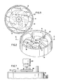
- Figure 1 shows a cross-sectional view of one embodiment of a feeding apparatus according to the present invention;
- Figure 2 shows a top perspective view of the rotary feeding drum of the feeding apparatus according to the present invention;
- Figure 3 shows a top view taken along lines 3-3' of a rotary feeding drum of the feeding shown in Figure 1;
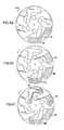
- Figures 4A, 4B and 4C show a feeding drum at different rotational positions to illustrate its operation;
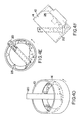
- Figures 4 D, 4E and 4F illustrate the function of a circular plate;
- Figure 5 shows a silicon replenishment apparatus for a crystal grower incorporating the feeding apparatus of Figure 1;
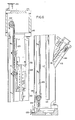
- Figure 6 shows, in more detail, an injector device of the apparatus of Figure 5;
- Figure 7 shows, in detail, power transmitting means between driving means and the rotary drum.
- Figures 1 through 4A-F illustrate one preferred embodiment of the apparatus for controllably feeding particulate material according to the present invention. As best shown in Figure 1, the apparatus includes a
drum 10 which is rotatably mounted about an axis which is inclined with reference to the horizontal. In the preferred embodiment, the angle of inclination is about 45° with reference to the horizontal A. However, different inclination angles could be selected from about 30° to about 60°. Thedrum 10 includes abottom wall 12 and an upstanding sideannular wall 14. In the preferred embodiment, as best shown in Figures 2 and 3, a plurality of identical cavities 11 are provided substantially in the inner surface of thebottom wall 12 of thedrum 10. In the illustrated embodiment, six such cavities 11 are equally spaced about the periphery of thedrum 10. - Each cavity 11 includes a
first portion 13 which is partially formed in the inner surface of theside wall 14 and extends in a direction substantially coinciding with the periphery of the drum into the inner surface of thebottom wall 12 of thedrum 10. Asecond portion 15 of each cavity 11 extends from thefirst portion 13 at one end towards the center of the bottom wall and is positioned generally transversely with respect to thefirst portion 13. Thesecond portion 15 at the other free end communicates withaperture 17 formed in thebottom wall 12 of thedrum 10. In the illustrated preferred embodiment, the first portion of the cavity has a larger volume than the second portion. In the preferred embodiment, each cavity is provided with separate outlet means for discharging the particulate material. However, instead of having a separate aperture for each cavity, a single, common outlet means can be conveniently provided in the central portion of the drum in communication with all of the cavities if the drum is supported and rotated by a means other than the centrally located means shown. - Provision of the plurality of cavities in the bottom wall of the drum for lifting and directing the particular material to the outlet means allows for smoother and more regular feeding of the material and increases the feeding rate accuracy.
- The particulate material is fed to the drum through a
feeding tube 20. The feeding tube is so positioned with respect to thebottom wall 12 of thedrum 10 that the particulate material is fed to any cavity 11 when such cavity is at its lowermost position with respect to the horizontal and preferably is fed at the location of the above-described first portion of such cavity. - Various other lifting shapes for the cavities may be used. Also, other configurations of cavities in the bottom wall of the drum may be provided. For example, the discharge apertures in the cavities may be positioned at the portion of the cavity adjacent the periphery of the drum's bottom wall instead of adjacent the drum's center. For such configuration, the feeding tube is positioned to feed each cavity while it is substantially at its highest position with respect to the horizontal rather than at its lower position as in the disclosed embodiment and directs the material to that portion of each cavity which is generally toward the central portion of the drum and thus removed from the location of the aperture, and the material then flows by gravity to each cavity's outlet when the respective cavity is rotated toward its lower position relative to the horizontal.
- The feeding apparatus is provided with means for blocking the flow of the particulate material from feeding
tube 20 to the cavity being filled. This is accomplished by terminating theend 22 of the feedingtube 20 at a predetermined distance (i.e. one quarter inch or so in 2 specific embodiments) above the tops of the cavities 11 so that movement of the particulate material from the feedingtube 20 becomes blocked and interrupted by previously deposited particulate material when the level of the material over the cavity reaches a predetermined level. - Preferably, the diameter of the feeding
tube 20, and all other parameters associated with the rate of material fed by the tube, are so selected that they do not constitute a limiting factor on the rate at which material is fed to the cavities. That is to say that for the maximum desired rate of feeding of the material, the feeding tube is intended to supply the material at that rate, and such rate is sufficient to fill each cavity to its maximum intended capacity at the highest expected rate of drum rotation. For lower drum rotation rates, corresponding to lower feed rates, excess supply of the material to the drum cavities is prevented by the blocking of the outlet end of the feed tube. The feed rate thus obtained is a function of substantially only the rate of drum rotation and the size and number of cavities; variables that are easy to control. This constitutes a distinct advantage over the previously mentioned belt-type feeders in which the material is fed from a feed tube onto a moving belt. In this method, the feed rate is not only dependent on belt velocity but also substantially on the distance between the belt and the end of the feed tube; a variable that, dependent on the physical character of the particulate material, can have a limited and critical useful range and can also be difficult to optimize and control under some conditions. - The
drum 10 is rotatably mounted on ashaft 19 coupled through rotatably supportive and vacuum sealing means 24 to a driving means 26 for rotating thedrum 10 at a preselected rotary speed. The driving means includes a variable speed electrical motor which is controlled by signals from a motor control unit 26. Figure 7 shows in greater detail power transmission means including a motor pulley 40, adrum pulley 42 and abelt 41. - The feeding apparatus further includes a funnel 23 which surrounds the
drum 10. Theenlarged portion 21 of the funnel 23 is coaxial with the drum, mounted about theshaft 19 and supported at the top bymeans 27 and at the bottom by means 29 within a housing 30. A feedingtube 20 which extends through an opening in the housing 30 and into thedrum 10 has anend 22 which is horizontally and vertically, adjustably mounted. The position of itsfree end 22 above the cavities 11 formed in thebottom wall 12 of thedrum 10 may be controlled by the operation of one or more of three equally spaced spring loadedbolts 28. The particulate material discharged from theaperture 17 in thebottom wall 12 of therotary drum 10 falls into the funnel 23. Means 34 are provided to direct the flow of the particulate material supplied to the funnel into a discharge outlet 36 provided in communication with the part of theenlarged portion 21 of the funnel 23 which is in the lowest position with respect to the horizontal. - Also, means are provided to ensure filling of the
first portion 13 of the cavities 11 with particulate material without any substantial filling of the material fed from the tube into thesecond portion 15 of the cavities 11. In the preferred embodiment, this is accomplished by provision of acircular plate 25 which is mounted about theshaft 19 and is dimensioned to cover at least a part of thefirst portion 13 and all of thesecond portion 15 of the cavities 11. - The operation of the present invention feeding apparatus is best illustrated in Figures 4A-4C which show the rotary drum in three different angular positions with reference to the horizontal A as it is rotating counterclockwise.
- In Figure 4A, the cavity designated as 11A is in its lowest position with respect to the horizontal, and is being filled with the particulate material supplied from feeding
tube 20 . Thefirst portion 13 of the cavity 11A is shown as filled with the particulate material, whereas thesecond portion 15 is empty. The cavity designated as 11B, which is in a higher position with respect to the horizontal than 11A and is in a counterclockwise direction from cavity 11A, has itsfirst portion 13 partially emptied of some of the particulate material which has entered into the secondtransverse portion 15 of the cavity 11B at this angular position of the drum. - In Figure 4B, cavity 11C is in its lowermost position with respect to the horizontal and the
first portion 13 of the cavity 11C is being filled with the particulate material to the predetermined level whereas in cavity 11A, a part of the particulate material has moved from thefirst portion 13 into thesecond portion 15 of the cavity. The particulate material in cavity 11B at this angular position of the drum with respect to the horizontal begins to fall, due to gravitational forces, from thesecond portion 15 of the cavity 11B into and throughaperture 17 at its end and is being discharged from the drum. - In Figure 4C, the particulate material in cavity 11B is almost fully discharged, whereas cavity 11D is now in its lowermost position and is fed with the particulate material supplied by the feeding tube. The feeding rate of the particulate material being discharged through the apertures communicating with each cavity is controlled substantially by the rate of rotation of the drum for a given size and shape of the cavities 11 and to the extent to which
circular plate 25 covers a portion of cavities 11 and the angle to the horizontal ofdrum 10. Figures 4D-4F illustrate more clearly the important function ofcircular plate 25. The particulate material actually rides about halfway up the leading counterclockwise side of the drum and forms a continuously avalanching "hill" of material. The circular plate prevents material from this hill from falling directly intosecond cavity portion 15 and throughaperture 17. Only material still in the cavityfirst portion 13 and to a lesser extent cavitysecond portion 15, that emerges above the top of the hill, will be transferred to drumaperture 17. - In a preferred embodiment, the repeatable feed rates are between 25g and 500g/minute. The structure of the drum and the fact that each cavity 11 completely empties during each drum revolution prevents material segregation. This basic design allows for feeding of particulate material having various sizes limited only by the dimensions and shapes of the cavities and apertures.
- Figure 5 shows one particularly suitable application of the present invention feeding apparatus as a silicon feeder mechanism for a silicon crystal growing furnace. The silicon feeder mechanism is used to feed granular silicon material at a known and controllable rate into the crucible of a silicon crystal grower furnace for the purpose of initially charging or replenishing material used after growing a crystal. A further possible use may be to continuously feed material to the crucible while the crystal is growing. This apparatus is adapted for controllable, accurate feeding with minimal contamination of the silicon material.
- In the apparatus shown in Figure 5, the silicon material is supplied into a
storage container 100 through asilicon refill port 101. Thestorage container 100 also includes an argon/vacuum connection inlet 102 and aview port 103 for visual inspection of the silicon material content in thestorage container 100. Theoutlet 104 of thestorage container 100 is connected through a disconnecting means 106 to afeeding tube housing 112 which forms a part of the apparatus forcontrollable feeding 114 which has structural features disclosed above in connection with the description of Figures 1-4. Feedingtube housing 112 containing feedingtube 20 supplies silicon material to the tilled rotary drum of theapparatus 114. The feeding rate at which the silicon material is being discharged from the drum is controlled by the rate of rotation of the tilted drum by the drum driving means 110. The rate of rotation of the drum driving means 110 is selected based on the conditions in the crucible. Predetermined parameters, such as total silicon weight and melt-down rate, and real-time parameters, such as temperature and visual indications, are typical considerations. Based on this information delivered from thefurnace 140 to the computer unit (not shown), appropriate feeding rates are also selected by the computer unit and output signals are sent to the input of the electronic controls of the drum driving means 110. - The tilted drum and associated feeding tube, collection funnel and motor drive have been designed to allow a predictable and controllable silicon material feed rate. The silicon feeding rate is very important in this application, since it must be matched to the furnace material meltdown rate capability. Additionally, known feeding rates are required in order to calculate the total amount of silicon material supplied to the crucible.
- The silicon material discharged from the apparatus for
controllable feeding 114 is delivered throughdischarge housing 113 containingdischarge tube 134 at a preselected rate to injection means 116. The injection means is shown in more detail in Figure 6. Injection means 116 includesretractable injector tube 117 extendable into thefurnace 140 for supplying the silicon material into the crucible. The injection means 116 includes ahousing 130 into which enters adischarge end 131 of thetube 134. Inside the housing aretractable injector tube 117 is movable between an extended position in which its dischargeforward end 121 is positioned inside thefurnace 140 and a retracted position in which theinjector tube 117 is positioned inside thehousing 130. Theinjector tube 117 is movably supported in thehousing 130 by aninjector tube support 132 and drivetrack rail 123 means. Adrive chain 125 extends between two spaced apartchain support sprockets Drive chain 125 followsdrive track rail 123 while pulling theinjector tube 117 in the injector tube support means 132. As shown in Figure 5, the injecting means 116 also includes driving means 119 forinjector tube 117 andelectronic controls 115 for controlling driving means 119. At the ends of the injecting means 116 argon/vacuum connection inlets vacuum isolation valve 118 is provided between the injecting means 116 and thefurnace 140. In the preferred embodiment, the electronic controls for the injecting means 115 are designed to enable beginning of rotation of the drum by computer control only when theinjector tube 117 is in a particular position with respect todischarge tube 134. In such position, theinlet 126 of theinjector tube 117 for receiving silicon material from thedischarge tube 134 is aligned with the outlet opening 131 in thetube 134. This electronic position interlock prevents silicon material from spilling intohousing 130 due to inadvertent rate input control tomotor control unit 110. - In this particular application, all materials in contact with the silicon material must be compatible with silicon handling and non-contaminating. Such materials may include tefzel for storage tank coating, teflon for delivering tubes and the drum, quartz for funnels and the feeding tube. Sizing of the various housings and the design of the internal components provides for future use of silicon as a construction material for many of the silicon handling parts.
- The present invention for controllable feeding of material to a crystal growing furnace is very useful since it allows for a more accurate feeding rate, eliminates spilling of the material, and allows for use of a very simple drum structure which requires little maintenance and can be made from a variety of rigid materials.
- Although the principles of the present invention have been described with reference to a particular embodiment, by way of example, it is understood that modifications may suggest themselves to those skilled in the art and it is intended that such modifications fall within the scope of the claims.
Claims (10)
- Apparatus for controllably feeding a particulate material, characterized by a drum mounted for rotation about an axis tilted at an acute angle with reference to a horizontal axis, said drum including a bottom wall having an inner surface, an outer periphery and a center and an annular, upstanding wall, at least one cavity, at least a portion of which is formed in the inner surface of said bottom wall, said cavity extending from about the outer periphery of said bottom wall at its one end and towards the center thereof at its other end, said cavity at one of its said ends communicating with at least one outlet means, means for supplying said particulate material into said at least one cavity, said supplying means having an outlet port for said material, said supplying means being so positioned in relation to the drum that said outlet port directs the material into the cavity only when said cavity is in a rotational position in which its end having said outlet means is elevated with respect to a horizontal plane above the opposite end of the same cavity, said supplying means being also so positioned that its said outlet end pours the material into that portion of the receiving cavity which is remote from the outlet means for such receiving cavity, means for blocking the flow of said particulate material to said cavity when the level of said particulate material above said cavity reaches a predetermined level, means for rotating said drum about said tilted axis, and means for controlling the rate of rotation of said drum, whereby upon rotation of said drum, said at least one cavity is filled with said particulate material fed from said supplying means during the rotation of said drum through a first angular portion of its rotation when said outlet means for said cavity is disposed above the already filled portion of the cavity and is emptied to discharge said material through said at least one outlet means by gravitational force during the rotation of said drum through a second angular portion of its rotation when said outlet means for the cavity is below the said filled portion of the cavity, the feeding rate of said material being discharged through said outlet means being controlled by the rate of rotation of said drum.
- Apparatus according to claim 1, characterized in that a plurality of cavities are provided substantially in the bottom wall and equally spaced along the periphery of said bottom wall, and in that each of said cavities comprises a first portion extending at least substantially along the periphery of said bottom wall and a second portion extending from said first portion at one end and towards the center of said bottom wall at the other end and transversely with respect to said first portion.
- Apparatus according to claim 2, characterized in that the outlet means includes a plurality of apertures one of said apertures being positioned at the other end of the second portion of each of the cavities.
- Apparatus according to claim 3, characterized in that the particulate material is fed only to the particular cavity which is in its lowest position with respect to the horizontal plane.
- Apparatus according to claim 2, characterized in that a circular plate is provided in the drum and is substantially adapted to cover at least a part of the first portions and all of the second portions of the cavities to eliminate said particulate material supplied from the means for supplying said material from moving into said second portions of said cavities while said cavities are in the lowermost position.
- Apparatus according to any of claims 1-5, characterized in that the drum is tilted at an angle of about 45° with respect to the horizontal.
- Apparatus according to any of claims 1 to 5, characterized in that the drum is tilted at an angle of between 30° and 60°.
- Apparatus according to any of claims 1-7, characterized in that the means for supplying the particulate material includes a feeding tube, in that the material blocking means includes the free end of said feeding tube positioned above the cavity at such a distance that the flow of said particulate material into said cavity is interrupted when the level of said particulate material in said cavity reaches a predetermined level.
- Apparatus according to claim 2, characterized in that the first portion of the cavity has a larger volume than the second portion.
- Apparatus according to claim 8, characterized in that the predetermined level is approximately the end of the feeding tube.
Applications Claiming Priority (2)
| Application Number | Priority Date | Filing Date | Title |
|---|---|---|---|
| US07/499,583 US5016683A (en) | 1990-03-27 | 1990-03-27 | Apparatus for controllably feeding a particulate material |
| US499583 | 1990-03-27 |
Publications (3)
| Publication Number | Publication Date |
|---|---|
| EP0449215A2 true EP0449215A2 (en) | 1991-10-02 |
| EP0449215A3 EP0449215A3 (en) | 1993-01-20 |
| EP0449215B1 EP0449215B1 (en) | 1997-01-02 |
Family
ID=23985831
Family Applications (1)
| Application Number | Title | Priority Date | Filing Date |
|---|---|---|---|
| EP91104786A Expired - Lifetime EP0449215B1 (en) | 1990-03-27 | 1991-03-26 | Apparatus for controllably feeding a particulate material |
Country Status (5)
| Country | Link |
|---|---|
| US (1) | US5016683A (en) |
| EP (1) | EP0449215B1 (en) |
| JP (1) | JP2916286B2 (en) |
| KR (1) | KR920005708A (en) |
| DE (1) | DE69123865T2 (en) |
Cited By (2)
| Publication number | Priority date | Publication date | Assignee | Title |
|---|---|---|---|---|
| WO2002060755A1 (en) * | 2001-01-29 | 2002-08-08 | Iwk Verpackungstechnik Gmbh | Tube filling machine |
| CN112225628A (en) * | 2020-09-27 | 2021-01-15 | 重庆航天工业有限公司 | Automatic pouring assembly and device for bridge plug gunpowder |
Families Citing this family (13)
| Publication number | Priority date | Publication date | Assignee | Title |
|---|---|---|---|---|
| US5387380A (en) * | 1989-12-08 | 1995-02-07 | Massachusetts Institute Of Technology | Three-dimensional printing techniques |
| US5204055A (en) * | 1989-12-08 | 1993-04-20 | Massachusetts Institute Of Technology | Three-dimensional printing techniques |
| JP3478406B2 (en) * | 1992-09-09 | 2003-12-15 | アルベマール・コーポレーシヨン | Equipment for supplying particulate matter |
| US5775402A (en) | 1995-10-31 | 1998-07-07 | Massachusetts Institute Of Technology | Enhancement of thermal properties of tooling made by solid free form fabrication techniques |
| US5814161A (en) * | 1992-11-30 | 1998-09-29 | Massachusetts Institute Of Technology | Ceramic mold finishing techniques for removing powder |
| US6146567A (en) * | 1993-02-18 | 2000-11-14 | Massachusetts Institute Of Technology | Three dimensional printing methods |
| US5660621A (en) * | 1995-12-29 | 1997-08-26 | Massachusetts Institute Of Technology | Binder composition for use in three dimensional printing |
| US8021483B2 (en) * | 2002-02-20 | 2011-09-20 | Hemlock Semiconductor Corporation | Flowable chips and methods for the preparation and use of same, and apparatus for use in the methods |
| SE0203667L (en) * | 2002-12-12 | 2004-06-13 | Eurocomp Ab | Feeding device |
| KR100704314B1 (en) * | 2006-12-11 | 2007-04-09 | 주식회사 신대특수재료 | Ultra high refractive optical resin composition having excellent heat resistance and manufacturing method of optical lens using the same |
| TW201012978A (en) * | 2008-08-27 | 2010-04-01 | Bp Corp North America Inc | Apparatus and method of use for a casting system with independent melting and solidification |
| US9372281B2 (en) | 2012-01-20 | 2016-06-21 | Koc Solution Co., Ltd. | Method for preparing thioepoxy-based optical material and polymerizable composition thereof |
| US10834807B1 (en) * | 2016-04-01 | 2020-11-10 | Elemental Scientific, Inc. | ICP torch assembly with retractable injector |
Family Cites Families (18)
| Publication number | Priority date | Publication date | Assignee | Title |
|---|---|---|---|---|
| US1553613A (en) * | 1925-09-15 | Feeder | ||
| US1221136A (en) * | 1916-08-28 | 1917-04-03 | Gen Engineering Co | Feeding-drum. |
| US1284700A (en) * | 1917-12-05 | 1918-11-12 | Mine & Smelter Supply Company | Rotary drum-feeder. |
| US1399124A (en) * | 1917-12-05 | 1921-12-06 | Mine & Smelter Supply Company | Feeder |
| DE528868C (en) * | 1930-04-12 | 1931-07-07 | Polte Fa | Device for the dimensionally accurate division of bulk goods |
| US2015164A (en) * | 1930-05-07 | 1935-09-24 | Fmc Corp | Method and apparatus for filling granular material into moving containers |
| US2998335A (en) * | 1956-02-04 | 1961-08-29 | Telefunken Gmbh | Method and apparatusfor growing single crystals from molten bodies |
| US2962363A (en) * | 1957-07-09 | 1960-11-29 | Pacific Semiconductors Inc | Crystal pulling apparatus and method |
| GB885146A (en) * | 1958-01-06 | 1961-12-20 | Inland Steel Co | Solids flow control device |
| NL237834A (en) * | 1958-04-09 | |||
| US3377003A (en) * | 1967-01-04 | 1968-04-09 | Sonoco Products Co | Dispensing container |
| US4249988A (en) * | 1978-03-15 | 1981-02-10 | Western Electric Company, Inc. | Growing crystals from a melt by controlling additions of material thereto |
| DE2925679A1 (en) * | 1979-06-26 | 1981-01-22 | Heliotronic Gmbh | METHOD FOR PRODUCING SILICON RODS |
| US4454096A (en) * | 1981-06-15 | 1984-06-12 | Siltec Corporation | Crystal growth furnace recharge |
| CA1261715A (en) * | 1984-07-06 | 1989-09-26 | General Signal Corporation | Apparatus and process for growing monocrystals of semiconductor materials from shallow crucibles by czochralski technique |
| US4661324A (en) * | 1985-02-15 | 1987-04-28 | Mobil Solar Energy Corporation | Apparatus for replenishing a melt |
| FR2592064B1 (en) * | 1985-12-23 | 1988-02-12 | Elf Aquitaine | DEVICE FOR FORMING A BATH OF MOLTEN SEMICONDUCTOR MATERIAL IN ORDER TO GROW A CRYSTALLINE ELEMENT THEREIN |
| DE3737051A1 (en) * | 1987-10-31 | 1989-05-11 | Leybold Ag | DEVICE FOR THE CONTINUOUS FEED OF MELT |
-
1990
- 1990-03-27 US US07/499,583 patent/US5016683A/en not_active Expired - Lifetime
-
1991
- 1991-03-26 DE DE69123865T patent/DE69123865T2/en not_active Expired - Fee Related
- 1991-03-26 EP EP91104786A patent/EP0449215B1/en not_active Expired - Lifetime
- 1991-03-26 JP JP3061989A patent/JP2916286B2/en not_active Expired - Fee Related
- 1991-03-28 KR KR1019910004918A patent/KR920005708A/en not_active Abandoned
Cited By (3)
| Publication number | Priority date | Publication date | Assignee | Title |
|---|---|---|---|---|
| WO2002060755A1 (en) * | 2001-01-29 | 2002-08-08 | Iwk Verpackungstechnik Gmbh | Tube filling machine |
| US6810928B2 (en) | 2001-01-29 | 2004-11-02 | Iwk Verpackungstechnik Gmbh | Tube filling machine |
| CN112225628A (en) * | 2020-09-27 | 2021-01-15 | 重庆航天工业有限公司 | Automatic pouring assembly and device for bridge plug gunpowder |
Also Published As
| Publication number | Publication date |
|---|---|
| JP2916286B2 (en) | 1999-07-05 |
| KR920005708A (en) | 1992-04-03 |
| DE69123865D1 (en) | 1997-02-13 |
| DE69123865T2 (en) | 1997-06-05 |
| US5016683A (en) | 1991-05-21 |
| JPH05301622A (en) | 1993-11-16 |
| EP0449215B1 (en) | 1997-01-02 |
| EP0449215A3 (en) | 1993-01-20 |
Similar Documents
| Publication | Publication Date | Title |
|---|---|---|
| US5016683A (en) | Apparatus for controllably feeding a particulate material | |
| US6121556A (en) | Granular material weighing system | |
| US4808042A (en) | Powder feeder | |
| US2800252A (en) | Powder-feeding apparatus | |
| CA1263231A (en) | Charging installation for a shaft furnace | |
| EP1209452A1 (en) | Weighing apparatus | |
| US5259533A (en) | Fish, bird and small animal feed dispenser | |
| US4300725A (en) | Apparatus for uniformly dispensing and distributing material | |
| CN210191864U (en) | Automatic weighing device | |
| EP0083227B1 (en) | Combinatorial weighing apparatus | |
| CN210618615U (en) | Weighing type screw filling packaging machine | |
| US4165823A (en) | Dispensing apparatus | |
| CN114111993A (en) | A medicine taking and automatic weighing device | |
| JP2000507905A (en) | Dry solids metering device with means for self-transfer and rapid transfer or cleaning | |
| US4293227A (en) | Spraying unit for unhardened concrete and the like | |
| WO1998005932A1 (en) | Multi-recipe dosing system | |
| CN1197854A (en) | Silicon feed system | |
| US6814111B1 (en) | Adjustable volume side discharge feeder | |
| EP1558901A1 (en) | Automatic combination weighing apparatus | |
| KR910000399B1 (en) | Supply apparatus and method of solid-liquid mixture | |
| US5962816A (en) | Combinatorial weighing apparatus | |
| CN112124653B (en) | Tube needle sorting equipment | |
| CN112166081A (en) | Material conveying mechanism and weighing system | |
| CN214358668U (en) | Weighing batching device and glass production line | |
| CN212512744U (en) | Coarse feeding control device and high-precision weighing system |
Legal Events
| Date | Code | Title | Description |
|---|---|---|---|
| PUAI | Public reference made under article 153(3) epc to a published international application that has entered the european phase |
Free format text: ORIGINAL CODE: 0009012 |
|
| AK | Designated contracting states |
Kind code of ref document: A2 Designated state(s): DE FR GB IT NL |
|
| PUAL | Search report despatched |
Free format text: ORIGINAL CODE: 0009013 |
|
| AK | Designated contracting states |
Kind code of ref document: A3 Designated state(s): DE FR GB IT NL |
|
| 17P | Request for examination filed |
Effective date: 19930614 |
|
| 17Q | First examination report despatched |
Effective date: 19941129 |
|
| GRAG | Despatch of communication of intention to grant |
Free format text: ORIGINAL CODE: EPIDOS AGRA |
|
| GRAH | Despatch of communication of intention to grant a patent |
Free format text: ORIGINAL CODE: EPIDOS IGRA |
|
| GRAH | Despatch of communication of intention to grant a patent |
Free format text: ORIGINAL CODE: EPIDOS IGRA |
|
| GRAA | (expected) grant |
Free format text: ORIGINAL CODE: 0009210 |
|
| AK | Designated contracting states |
Kind code of ref document: B1 Designated state(s): DE FR GB IT NL |
|
| ITF | It: translation for a ep patent filed | ||
| REF | Corresponds to: |
Ref document number: 69123865 Country of ref document: DE Date of ref document: 19970213 |
|
| ET | Fr: translation filed | ||
| PLBE | No opposition filed within time limit |
Free format text: ORIGINAL CODE: 0009261 |
|
| STAA | Information on the status of an ep patent application or granted ep patent |
Free format text: STATUS: NO OPPOSITION FILED WITHIN TIME LIMIT |
|
| 26N | No opposition filed | ||
| PGFP | Annual fee paid to national office [announced via postgrant information from national office to epo] |
Ref country code: GB Payment date: 19980223 Year of fee payment: 8 |
|
| PGFP | Annual fee paid to national office [announced via postgrant information from national office to epo] |
Ref country code: NL Payment date: 19980228 Year of fee payment: 8 |
|
| PGFP | Annual fee paid to national office [announced via postgrant information from national office to epo] |
Ref country code: FR Payment date: 19990218 Year of fee payment: 9 |
|
| PG25 | Lapsed in a contracting state [announced via postgrant information from national office to epo] |
Ref country code: GB Free format text: LAPSE BECAUSE OF NON-PAYMENT OF DUE FEES Effective date: 19990326 |
|
| PG25 | Lapsed in a contracting state [announced via postgrant information from national office to epo] |
Ref country code: NL Free format text: LAPSE BECAUSE OF NON-PAYMENT OF DUE FEES Effective date: 19991001 |
|
| GBPC | Gb: european patent ceased through non-payment of renewal fee |
Effective date: 19990326 |
|
| NLV4 | Nl: lapsed or anulled due to non-payment of the annual fee |
Effective date: 19991001 |
|
| PGFP | Annual fee paid to national office [announced via postgrant information from national office to epo] |
Ref country code: DE Payment date: 20000222 Year of fee payment: 10 |
|
| PG25 | Lapsed in a contracting state [announced via postgrant information from national office to epo] |
Ref country code: FR Free format text: LAPSE BECAUSE OF NON-PAYMENT OF DUE FEES Effective date: 20001130 |
|
| REG | Reference to a national code |
Ref country code: FR Ref legal event code: ST |
|
| PG25 | Lapsed in a contracting state [announced via postgrant information from national office to epo] |
Ref country code: DE Free format text: LAPSE BECAUSE OF NON-PAYMENT OF DUE FEES Effective date: 20020101 |
|
| PG25 | Lapsed in a contracting state [announced via postgrant information from national office to epo] |
Ref country code: IT Free format text: LAPSE BECAUSE OF NON-PAYMENT OF DUE FEES;WARNING: LAPSES OF ITALIAN PATENTS WITH EFFECTIVE DATE BEFORE 2007 MAY HAVE OCCURRED AT ANY TIME BEFORE 2007. THE CORRECT EFFECTIVE DATE MAY BE DIFFERENT FROM THE ONE RECORDED. Effective date: 20050326 |