EP0449224A1 - Apparat zum Einschalten von einer Entladungslampe - Google Patents
Apparat zum Einschalten von einer Entladungslampe Download PDFInfo
- Publication number
- EP0449224A1 EP0449224A1 EP91104798A EP91104798A EP0449224A1 EP 0449224 A1 EP0449224 A1 EP 0449224A1 EP 91104798 A EP91104798 A EP 91104798A EP 91104798 A EP91104798 A EP 91104798A EP 0449224 A1 EP0449224 A1 EP 0449224A1
- Authority
- EP
- European Patent Office
- Prior art keywords
- frequency
- discharge lamp
- soft
- output
- circuit
- Prior art date
- Legal status (The legal status is an assumption and is not a legal conclusion. Google has not performed a legal analysis and makes no representation as to the accuracy of the status listed.)
- Withdrawn
Links
Images


Classifications
-
- H—ELECTRICITY
- H05—ELECTRIC TECHNIQUES NOT OTHERWISE PROVIDED FOR
- H05B—ELECTRIC HEATING; ELECTRIC LIGHT SOURCES NOT OTHERWISE PROVIDED FOR; CIRCUIT ARRANGEMENTS FOR ELECTRIC LIGHT SOURCES, IN GENERAL
- H05B41/00—Circuit arrangements or apparatus for igniting or operating discharge lamps
- H05B41/14—Circuit arrangements
- H05B41/26—Circuit arrangements in which the lamp is fed by power derived from DC by means of a converter, e.g. by high-voltage DC
- H05B41/28—Circuit arrangements in which the lamp is fed by power derived from DC by means of a converter, e.g. by high-voltage DC using static converters
- H05B41/295—Circuit arrangements in which the lamp is fed by power derived from DC by means of a converter, e.g. by high-voltage DC using static converters with semiconductor devices and specially adapted for lamps with preheating electrodes, e.g. for fluorescent lamps
-
- H—ELECTRICITY
- H05—ELECTRIC TECHNIQUES NOT OTHERWISE PROVIDED FOR
- H05B—ELECTRIC HEATING; ELECTRIC LIGHT SOURCES NOT OTHERWISE PROVIDED FOR; CIRCUIT ARRANGEMENTS FOR ELECTRIC LIGHT SOURCES, IN GENERAL
- H05B41/00—Circuit arrangements or apparatus for igniting or operating discharge lamps
- H05B41/14—Circuit arrangements
- H05B41/24—Circuit arrangements in which the lamp is fed by high frequency AC, or with separate oscillator frequency
Definitions
- the present invention relates to an apparatus for operating discharge lamp and, more specifically, to a an apparatus for operating discharge lamp for turning on a discharge lamp such as a fluorescent lamp by a high-frequency output.
- an electronic lighting apparatus has been used for turning on a discharge lamp, such as a fluorescent lamp, by a high-frequency output generated by a high-frequency generator.
- a high-frequency generator capable of varying its output frequency is used as a lighting apparatus.
- a relationship between its output voltage and frequency is as follows.
- the output frequency of the high-frequency generator is set to be higher, e.g., 69 kHz, than that, e.g., 42 kHz, used for normal ON operation, so that the output voltage to the discharge lamp is lowered. Namely, so-called soft start is performed.
- a discharge lamp lighting apparatus having this characteristic has been proposed to prolong the service life of the discharge lamp.
- the output frequency to the discharge lamp is controlled to vary toward the frequency for the normal ON operation. Therefore, even after the discharge lamp is turned on, the output frequency gradually changes in accordance with a time constant. This delays rising of the output voltage and it takes several seconds before a desired brightness is achieved, resulting in discomfort to the user.
- an object of the present invention to provide an apparatus for operating discharge lamp in which, at a start operation, it is detected that a discharge lamp is turned on and soft start is stopped, so that the brightness of the lamp can be instantaneously changed to a desired level.
- an apparatus for operating discharge lamp comprising: a discharge lamp; direct-current power source means for supplying a direct current to the discharge lamp; high-frequency generating means capable of varying a direct-current output frequency from the direct-current power source means; soft-start circuit means for controlling, upon a start operation, the output frequency of the high-frequency generating means to be lower than that for a normal ON operation of the discharge lamp and to be changed to a level for the normal ON operation; ON detecting means for detecting that the discharge lamp is ON; and soft-start release means for switching the output frequency of the high-frequency generating means to that for the normal ON operation when the ON detecting means performs ON detection.
- a DC power source 12 comprises a commercial AC power source 14, a rectifier 16 for rectifying the power from the power source 14, and a smoothing circuit 18 for smoothing the output from the rectifier 16 to obtain a DC output.
- the DC power source 12 is connected to an inverter 20 as a high-frequency generator.
- a high-frequency output is generated in accordance with an oscillated frequency output from an oscillator 22 connected to the inverter 20.
- a dimmer circuit 23 is connected between the DC power source 12 and the oscillator 22, and a switch b is inserted between the DC power source 12 and the dimmer circuit 23.
- the inverter 20 can be, e.g., a half bridge inverter comprising a pair of transistors Q1 and Q2, as shown in Fig. 1.
- Discharge lamps 241 and 242 e.g., fluorescent lamps, respectively, have capacitors C1 and C2.
- a high-frequency output is supplied from the inverter 20 to both electrodes of the discharge lamp 241 through a capacitor C3 and a choke coil CH1, and to both electrodes of the discharge lamp 242 through the capacitor C3 and a choke coil CH2.
- Terminal voltages V L1 and V L2 of the discharge lamps 241 and 242, respectively, are detected by a voltage detector 26 comprising resistors R1, R2, R3, R4, and R5, capacitors C4, C5, and C6, diodes D1, D2, D3, and D4, and the like, as shown in Fig. 1.
- the terminal voltages V L1 and V L2 of the discharge lamps 241 and 242, respectively, are high when the corresponding discharge lamps are not ON, and are low when the corresponding discharge lamps are ON. Even when the discharge lamps are ON, if the service life of the discharge lamps 241 and 242 is running short after long-time use, the terminal voltages V L1 and V L2 are low.
- the output frequency from the inverter 20 to be supplied to the discharge lamps 241 and 242 is set higher than that for normal ON operation, and an output voltage applied to the discharge lamps 241 and 242 is set low.
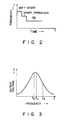
- so-called soft start is performed. More specifically, the relationship between the frequency and the output voltage is as shown in Fig. 2. In a low-frequency band with a resonance frequency f0 at its center, as the frequency is increased, the output voltage is increased. Contrary to this, in a high-frequency band, as the frequency is increased, the output voltage is decreased.
- an output voltage f s is set at 69 kHz, which is higher than a frequency f a of 42 kHz for the normal ON operation, and the output voltage applied to the discharge lamps 241 and 242 is set low.
- the oscillator 22 is connected to an ON frequency circuit 28 through a diode D5, and to a soft-start circuit 30 through a diode D6 and a switch SW1.
- Each of the ON frequency circuit 28 and the soft-start circuit 30 supplies an oscillation control signal to the oscillator 22 so that a frequency having the above relationship with the output voltage is output from the inverter 20. More specifically, it is designed that the oscillation control signal from the soft-start circuit 30 causes a higher-frequency output than that from the ON frequency circuit 28 does.
- the oscillation control signal from the soft-start circuit 30 is applied to the oscillator 22 through the switch SW1.
- a soft-start release circuit 32 is connected to an ON detector 34 and at the same time to the soft-start circuit 30 through the switch SW1.
- the ON detector 34 receives the terminal voltages V L1 and V L2 of the discharge lamps 241 and 242 from an output terminal a of the voltage detector 26 and detects from a voltage drop that the discharge lamps 241 and 242 are ON.
- the soft-start release circuit 32 is enabled when the ON detector 34 detects the ON state of the discharge lamps 241 and 242. As a result, the output from the soft-start circuit 30 is locked and is not input to the oscillator 22, thereby releasing the soft-start operation.
- the circuit of Fig. 1 as the basic circuit configuration further comprises a starter 36, a safety circuit 38, a power ON-time reset circuit 40, a power OFF-time reset circuit 42, and the like.
- a DC power source has a step-down insulated transformer Tr1.
- the primary winding of the transformer Tr1 is the commercial AC power source 14 side, and the secondary winding thereof is the rectifier 16 side.
- the soft-start circuit 30 constitutes a kind of differentiator, and has a capacitor C7 and resistors R6 and R7 series-connected between a power source Vref and the ground voltage.
- the capacitor C7 is charged. Accordingly, a terminal voltage, corresponding to an upper terminal in the drawing, of the resistor R7 rises instantaneously, and simultaneously starts to drop in accordance with a predetermined time constant. This terminal voltage of the resistor R7 becomes the output voltage of the soft-start circuit 30.
- the output voltage is then divided by resistors R8, R9 and R10 through a diode D7, and is applied as an oscillation control signal to the base of an npn transistor Q3 having an emitter grounded through a resistor R11.
- the oscillator 22 comprises, e.g., a voltage/frequency converter (to be referred to as a V/F converter hereinafter) and is connected to the collector of the transistor Q3.
- the V/F converter 22 oscillates in response to a frequency proportional to the voltage applied to the base of the transistor Q3, thereby driving the inverter 20 through an output transformer Tr2 or Tr3.
- the inverter 20 outputs a frequency sufficiently higher than that for the normal ON operation.
- the output frequency of the inverter 20 is lowered. In this manner, the output voltage to be applied to the discharge lamps 241 and 242 is gradually increased, thereby executing soft start.
- the starter 36 is connected between the DC power source 12 and the ON detector 34, and comprises a capacitor C8, transistors Q4 and Q5, and resistors R12, R13, R14, and R15.
- the starter 36 sets the terminal voltage of the capacitor C7 at 0 V, thereby reliably enabling the soft-start circuit 30. Namely, upon start operation, the capacitor C8 is charged by a power source Vcc, so that the npn transistor Q5 is kept ON for a predetermined period of time to decrease its collector potential (serving as the collector potential of the transistor Q3).
- the ON detector 34 has two npn transistors Q6 and Q7.
- the terminal voltages V L1 and V L2 of the discharge lamps 241 and 242 (not shown) are applied to the base of the transistor Q6.
- the collector of the transistor Q6 is connected to the power source Vcc, and the emitter thereof is grounded through resistors R16 and R17.
- the base of the other transistor Q7 is connected between the resistors R16 and R17, the collector thereof is connected to the power source Vcc through a resistor R18, and the emitter thereof is grounded.
- the safety circuit 38 increases the output frequency of the inverter 20 to lower the output voltage to the discharge lamps 241 and 242, thereby ensuring safety. More specifically, the safety circuit 38 receives the potential at the node of the emitter of the transistor Q6 and the resistor R16 of the ON detector 34. When the potential at the node of the resistor R16 and the emitter of the transistor Q6 is increased, a capacitor C9 is charged through a resistor R19. When the terminal voltage of the capacitor C9 exceeds the Zener voltage of a Zener diode ZD1, a transistor Q8 is turned on. As a result, a flip-flop FF having NOR gates 2 and 3 is enabled through a NOR gate NOR1, turning on a transistor Q9 through a diode D8. The transistor Q8 is connected to resistors R20 and R21.
- the output voltage of the soft-start circuit 30, i.e., the potential at the node of the resistors R6 and R7 is kept high.
- the collector potential of a transistor Q10 is increased through a diode D9.
- a transistor Q11 (to be described later) of the soft-start release circuit 32 is OFF.
- the output voltage of the soft-start circuit 30 is applied to the base of the transistor Q3 through the diode D7 and the resistor R8.
- the voltage occurring at the node of the emitter of the transistor Q6 and the resistor R16 in accordance with the increase in voltages V L1 and V L2 is divided by resistors R22 and R23 and applied to the base of the transistor Q3 through a diode D10 and the resistor R8.
- the soft-start release circuit 32 has an npn transistor Q11 and resistors R24 and R25.
- the base of the transistor Q11 is connected to the collector of the transistor Q7 of the ON detector 34 through the resistor R24.
- the collector of the transistor Q11 is connected to the node of the resistors R6 and R7 that constitute the soft-start circuit 30, the emitter thereof is grounded, and the base thereof is grounded through the resistor R25.
- the discharge lamps 241 and 242 are not ON, the terminal voltages V L1 and V L2 thereof are high, as described above, and the transistors Q6 and Q7 are ON.
- the collector potentials of the transistors Q6 and Q7 are decreased to the ground potential.
- the transistor Q11 is OFF, and the output voltage of the soft-start circuit 30 is output unchanged, thus executing the soft-start operation described above.
- the output of the ON frequency circuit 28 is applied to the base of the transistor Q3 through a diode D11 as the oscillation control signal.
- the inverter 20 is controlled in accordance with the oscillation control signal input from the ON frequency circuit 28.
- the ON frequency circuit 28 has an arrangement as shown in Fig. 4. Namely, resistors R26, R27, R28, and R29, a diode D12, a Zener diode ZD2, and a capacitor C10 are connected between one input terminal of a NAND circuit NA1 and an input terminal b , and resistors R30, R31, and R32, and a transistor Q12 are connected to the output terminal of the NAND circuit NA1.
- the ON frequency circuit 28 outputs a high-level voltage from its NAND circuit NA1 so that the inverter 20 outputs a predetermined frequency for the normal ON operation to the discharge lamps 241 and 242. Then, the transistor Q12 is turned off to supply a predetermined output (oscillation control signal) to the base of the transistor Q3.
- a dimming signal is input to the input terminal b , the output voltage (oscillation control signal) to be applied to the transistor Q3 is varied through the diode D11.
- the oscillation frequency of the V/F converter 22 is changed to change the output frequency of the inverter 20, thus performing dimming control of the discharge lamps 241 and 242.
- the transistor Q7 is ON for a predetermined period of time during the start operation, and the input terminal of a NAND circuit NA2 provided to the input side of the reset circuit 40 becomes low level.
- the output terminal of a NAND circuit NA3 provided to the output side of the reset circuit 40 becomes low level through a capacitor C11, resistors R33 and R34, and a diode D13.
- the pnp transistor Q9 connected to both terminals of the capacitor C7 provided to the soft-start circuit 30 is turned on through a diode D14 and resistors R35 and R36 to discharge the capacitor C7.
- the terminal voltage of the capacitor C7 becomes 0 V, and the soft-start circuit 30 is reliably reset in an enabled state.
- a predetermined pulse signal is input to a terminal c of the power OFF-time reset circuit 42.
- a transistor Q10 is kept OFF for predetermined period of time by this pulse signal through resistors R37 and R38, and the transistor Q9 is kept ON through a diode D15 during this period of time.
- the capacitor C7 is discharged to reset the soft-start circuit 30.
- the capacitor C9 is discharged through the diode D9 to reset the safety circuit 38.
- the safety circuit 38 detects this state and increases the output frequency of the inverter 20 to protect the discharge lamps 241 and 242, thus lowering the voltage to be supplied to the discharge lamps 241 and 242.
- the values of the respective circuit elements must be set such that the safety circuit 38 does not operate during the start operation of the discharge lamps 241 and 242.
- the starter 36 and the power ON-time reset circuit 40 are operated, and the potential of the capacitor C7 of the soft-start circuit 30 are set at 0 V by the transistor Q9, thus reliably setting the enable state.
- the transistor Q9 is turned off.
- the capacitor C7 is charged.
- the output voltage (the potential at the node of the resistors R6 and R7) of the soft-start circuit 30 rises instantaneously, and then continuously drops by a predetermined time constant.
- the output voltage is applied to the V/F converter 22 as the oscillation control signal through the diode D7 and the transistor Q3 to change the oscillation frequency of the V/F converter 22 and the output frequency of the inverter 20.
- the initial value of the output voltage of the soft-start circuit 30 is set in such a manner to cause the inverter 20 to output a frequency sufficiently higher than that for the normal ON operation of the discharge lamps 241 and 242.
- the output frequency of the inverter 20 is continuously increased. In this manner, the soft-start operation to continuously increase the output voltage to the discharge lamps 241 and 242 from a low value in accordance with the time constant is performed.
- the ON detector 34 detects this and increases the collector potential of the transistor Q7 thereof.
- the transistor Q11 of the soft-start release circuit 32 is turned on to stop the operation of the soft-start circuit 30.
- the voltage (soft-start oscillation control signal) applied to the base of the transistor Q3 is decreased at once down to the level of the output voltage (normal ON oscillation control signal) from the ON frequency circuit 28. More specifically, before the discharge lamps 241 and 242 are turned on, as the output voltage from the soft-start circuit 30 changes, the output frequency supplied to the discharge lamps 241 and 242 gradually decreases in accordance with the predetermined time constant. However, once the lamps 241 and 242 are turned on, the soft-start circuit 30 is stopped, and the output frequency to the lamps 241 and 242 decreases at once down to the level for the normal ON operation (the output voltage rises at once). As a result, the brightness of the lamps 241 and 242 rises instantaneously. The conventional problem of discomfort to the user before a desired brightness is achieved can thus be solved.
- the inverter 20 can be of any type, such as a one-transistor type inverter, as far as the output frequency is variable.
- the soft-start circuit 30 can be of a type that switches the output frequency in a stepwise manner.
- the soft-start release circuit 32 can be of a type that forcibly switches the output frequency to the level of the normal ON operation regardless of the soft-start circuit 30.
Landscapes
- Circuit Arrangements For Discharge Lamps (AREA)
- Inverter Devices (AREA)
Applications Claiming Priority (1)
| Application Number | Priority Date | Filing Date | Title |
|---|---|---|---|
| JP2081645A JPH03283297A (ja) | 1990-03-29 | 1990-03-29 | 放電灯点灯装置 |
Publications (1)
| Publication Number | Publication Date |
|---|---|
| EP0449224A1 true EP0449224A1 (de) | 1991-10-02 |
Family
ID=13752079
Family Applications (1)
| Application Number | Title | Priority Date | Filing Date |
|---|---|---|---|
| EP91104798A Withdrawn EP0449224A1 (de) | 1990-03-29 | 1991-03-26 | Apparat zum Einschalten von einer Entladungslampe |
Country Status (3)
| Country | Link |
|---|---|
| EP (1) | EP0449224A1 (de) |
| JP (1) | JPH03283297A (de) |
| KR (1) | KR940003773B1 (de) |
Cited By (2)
| Publication number | Priority date | Publication date | Assignee | Title |
|---|---|---|---|---|
| CN1096822C (zh) * | 1994-02-15 | 2002-12-18 | 松下电工株式会社 | 高压放电灯点亮装置 |
| EP0740494A3 (de) * | 1995-04-27 | 2003-11-05 | Patent-Treuhand-Gesellschaft für elektrische Glühlampen mbH | Schaltungsanordnung zum Impulsbetrieb von Entladungslampen |
Families Citing this family (5)
| Publication number | Priority date | Publication date | Assignee | Title |
|---|---|---|---|---|
| JP2002164190A (ja) * | 2000-11-22 | 2002-06-07 | Matsushita Electric Ind Co Ltd | 陰極放電管の駆動装置及び方法 |
| JP4400872B2 (ja) * | 2004-07-16 | 2010-01-20 | 株式会社小糸製作所 | 放電灯点灯装置 |
| CN101668374A (zh) * | 2004-11-05 | 2010-03-10 | 太阳诱电株式会社 | 亮灯装置 |
| KR100877831B1 (ko) * | 2007-12-14 | 2009-01-08 | 엘지이노텍 주식회사 | 인버터의 주파수 가변회로 |
| JP5077020B2 (ja) * | 2008-03-31 | 2012-11-21 | 株式会社Jvcケンウッド | 無線受信機のlcdバックライト駆動装置 |
Citations (2)
| Publication number | Priority date | Publication date | Assignee | Title |
|---|---|---|---|---|
| EP0091724A1 (de) * | 1982-02-11 | 1983-10-19 | North American Philips Lighting Corporation | Ballastvorrichtung zum Betrieb einer Entladungslampe |
| DE3432266A1 (de) * | 1983-09-06 | 1985-03-21 | F. Knobel Elektro-Apparatebau AG, Ennenda | Elektronisches vorschaltgeraet fuer fluoreszenzlampen sowie verfahren zu dessen betrieb |
-
1990
- 1990-03-29 JP JP2081645A patent/JPH03283297A/ja active Pending
-
1991
- 1991-03-26 EP EP91104798A patent/EP0449224A1/de not_active Withdrawn
- 1991-03-28 KR KR1019910004907A patent/KR940003773B1/ko not_active Expired - Fee Related
Patent Citations (2)
| Publication number | Priority date | Publication date | Assignee | Title |
|---|---|---|---|---|
| EP0091724A1 (de) * | 1982-02-11 | 1983-10-19 | North American Philips Lighting Corporation | Ballastvorrichtung zum Betrieb einer Entladungslampe |
| DE3432266A1 (de) * | 1983-09-06 | 1985-03-21 | F. Knobel Elektro-Apparatebau AG, Ennenda | Elektronisches vorschaltgeraet fuer fluoreszenzlampen sowie verfahren zu dessen betrieb |
Cited By (2)
| Publication number | Priority date | Publication date | Assignee | Title |
|---|---|---|---|---|
| CN1096822C (zh) * | 1994-02-15 | 2002-12-18 | 松下电工株式会社 | 高压放电灯点亮装置 |
| EP0740494A3 (de) * | 1995-04-27 | 2003-11-05 | Patent-Treuhand-Gesellschaft für elektrische Glühlampen mbH | Schaltungsanordnung zum Impulsbetrieb von Entladungslampen |
Also Published As
| Publication number | Publication date |
|---|---|
| KR940003773B1 (ko) | 1994-04-30 |
| KR910017911A (ko) | 1991-11-05 |
| JPH03283297A (ja) | 1991-12-13 |
Similar Documents
| Publication | Publication Date | Title |
|---|---|---|
| US7084582B2 (en) | Electronic ballast system having emergency lighting provisions and electronic chip | |
| US5739645A (en) | Electronic ballast with lamp flash protection circuit | |
| US5142202A (en) | Starting and operating circuit for arc discharge lamp | |
| JP2002515173A (ja) | 蛍光ランプのバラストドライバ用のフリッカ防止機構 | |
| JP4120192B2 (ja) | 放電灯点灯装置 | |
| KR940003773B1 (ko) | 방전등 점등장치 | |
| EP0691799B1 (de) | Schaltung zum Betreiben eines elektronischen Verschaltgerätes ohne Verzögerung | |
| US5087862A (en) | Discharge lamp lighting apparatus for controlling voltage of switching transistor by raising starting voltage | |
| JP2600712Y2 (ja) | ソーラーランプ | |
| JPH06165517A (ja) | 高節電型インバ−タ | |
| JP3422146B2 (ja) | 電源装置 | |
| JP3707101B2 (ja) | 無電極放電灯点灯装置 | |
| JP2658042B2 (ja) | 放電灯点灯装置 | |
| JP2721523B2 (ja) | インバータ回路 | |
| JP3059524B2 (ja) | 放電灯点灯装置 | |
| KR200255427Y1 (ko) | 음극예열전류 제어회로를 내장한 전자식 안정기 | |
| JP3694146B2 (ja) | 放電灯点灯装置 | |
| JP2002170695A (ja) | 放電灯点灯装置 | |
| JP2003333745A (ja) | 電源装置 | |
| JPH0244698A (ja) | 放電ランプ点灯装置 | |
| JP2000106291A (ja) | 放電ランプ点灯装置および照明器具 | |
| JPH08111290A (ja) | 電源装置 | |
| JPH08241133A (ja) | 白熱電球用定電流定電圧直流電源 | |
| KR970004129B1 (ko) | 밸러스트 제어기 | |
| JP2749315B2 (ja) | インバータ装置 |
Legal Events
| Date | Code | Title | Description |
|---|---|---|---|
| PUAI | Public reference made under article 153(3) epc to a published international application that has entered the european phase |
Free format text: ORIGINAL CODE: 0009012 |
|
| 17P | Request for examination filed |
Effective date: 19910423 |
|
| AK | Designated contracting states |
Kind code of ref document: A1 Designated state(s): DE GB |
|
| STAA | Information on the status of an ep patent application or granted ep patent |
Free format text: STATUS: THE APPLICATION IS DEEMED TO BE WITHDRAWN |
|
| 18D | Application deemed to be withdrawn |
Effective date: 19931001 |