EP0449532A2 - Equipement respiratoire de secours - Google Patents
Equipement respiratoire de secours Download PDFInfo
- Publication number
- EP0449532A2 EP0449532A2 EP91302532A EP91302532A EP0449532A2 EP 0449532 A2 EP0449532 A2 EP 0449532A2 EP 91302532 A EP91302532 A EP 91302532A EP 91302532 A EP91302532 A EP 91302532A EP 0449532 A2 EP0449532 A2 EP 0449532A2
- Authority
- EP
- European Patent Office
- Prior art keywords
- flow path
- pressure
- diaphragm
- demand
- trigger element
- Prior art date
- Legal status (The legal status is an assumption and is not a legal conclusion. Google has not performed a legal analysis and makes no representation as to the accuracy of the status listed.)
- Withdrawn
Links
Images
Classifications
-
- A—HUMAN NECESSITIES
- A62—LIFE-SAVING; FIRE-FIGHTING
- A62B—DEVICES, APPARATUS OR METHODS FOR LIFE-SAVING
- A62B9/00—Component parts for respiratory or breathing apparatus
- A62B9/02—Valves
-
- Y—GENERAL TAGGING OF NEW TECHNOLOGICAL DEVELOPMENTS; GENERAL TAGGING OF CROSS-SECTIONAL TECHNOLOGIES SPANNING OVER SEVERAL SECTIONS OF THE IPC; TECHNICAL SUBJECTS COVERED BY FORMER USPC CROSS-REFERENCE ART COLLECTIONS [XRACs] AND DIGESTS
- Y10—TECHNICAL SUBJECTS COVERED BY FORMER USPC
- Y10T—TECHNICAL SUBJECTS COVERED BY FORMER US CLASSIFICATION
- Y10T137/00—Fluid handling
- Y10T137/2496—Self-proportioning or correlating systems
- Y10T137/2544—Supply and exhaust type
Definitions
- THIS INVENTION concerns emergency breathing equipment intended to provide a short term supply of breathable gas to a user in a hazardous atmosphere or during temporary submersion.
- Applications of the equipment to which the invention is directed are escape from smoke-filled enclosures such as aircraft cabins by aircrew and passengers or from military vehicles or vessels; crew escape from submerged enclosures such as ditched aircraft and helicopters; and immediate use by rescue personnel such as firefighters, ambulance crews and so on in the absence of or while donning conventional long term self contained breathing equipment.
- the equipment should be compact and light in weight; be rugged and simple to use, especially by unpractised users; and be reliable and self-adapting to the requirements of different users and different operational circumstances.
- Breathing equipment for these purposes essentially comprises a suitable self-contained source of breathable gas such as clean air stored at high pressure in a suitable vessel; and means for delivering this breathing gas at a suitable pressure and in required quantities to a point of use such as a breathing mask: that is to say, the essential components correspond with those of a conventional self-contained breathing apparatus, the means for delivery of breathing gas at a required pressure and in required quantities typically comprising a pressure-regulator and suitable flow-control devices that may include a demand valve.
- the different lung capacities of individuals affect the rate of air consumption at maximum breathing rates such as occur when the individual is engaged in strenuous physical activity or is subject to high general stress levels.
- the air consumption rate necessary to sustain life is in general substantially less than the maximum corresponding with unrestrained breathing and in many circumstances a restraint on breathing rate is desirable to prevent hyperventilation and its undesirable physiological consequences. Indeed, if there is restraint upon the rate of air consumption not only is hyperventilation prevented but a calming influence is exerted.
- the lung capacities of individuals may differ significantly, their air consumption rates at a life-sustaining level are remarkably similar. The present invention utilises this phenomenon.
- the invention provides emergency breathing equipment that is characterised by a demand valve comprising a poppet controlling a restricted inhalation flow path from a breathing gas inlet to a user connection, said poppet being operable by a demand pressure-sensing diaphragm exposed to said user connection and controlling an exhalation flow path between the user connection and an exhaust port such that demand pressure changes shift the diaphragm between a first position in which it opens the inhalation flow path and closes the exhalation flow path, and a second position in which it closes the inhalation flow path and opens the exhalation flow path.
- the diaphragm actuates the poppet through a pusher member partly defining the inhalation flow path and itself subject to demand pressure independently of the diaphragm to provide for secondary control of the poppet in the event of failure of the diaphragm, movement of the pusher member relative to the diaphragm both operating the poppet and controlling an auxiliary exhalation flow path.
- the construction of the demand valve permits the gas spaces therewithin to be of small volume, thereby providing for sensitivity and rapid response to demand pressure changes, while avoiding wastage of breathing gas during valve changeover in a breathing cycle.
- the construction further permits the demand valve to have small overall physical size such as to make its integration in a simple lightweight breathing mask a practical possibility.
- the invention also consists in emergency breathing equipment that is characterised by a reactive pressure regulator (such as for instance disclosed in GB-A-1 511 844) adapted to deliver breathing gas at a fixed low pressure from a high pressure source and having its reaction load means controlled by a removable or displaceable trigger element that in an installed position disables the reaction load means.
- a reactive pressure regulator such as for instance disclosed in GB-A-1 511 844
- a removable or displaceable trigger element that in an installed position disables the reaction load means.
- the trigger element serves to switch the regulator output pressure between zero and the fixed low pressure setting for breathing gas delivery, thereby providing efficient on/off switching of the regulator output.
- the trigger element is preferably operable by another part of the equipment in such manner that the regulator is automatically switched to deliver breathing gas by the act of moving that other part of the equipment from a stowed out of use condition.
- the trigger element forms part of a breathing mask or demand valve.
- the trigger element may for instance take the form of a probe that inserted into a passage in the regulator body operates a follower mechanism interposed the reaction load means and the reaction member to withdraw the former from the latter.
- the probe may be formed with a detent notch to receive a detent when fully inserted, thereby to retain the probe in position and to avoid its inadvertent withdrawal.
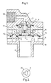
- the demand valve illustrated in Figures 1 and 2 comprises a body having a control inlet passage 1 terminating in a seat for a poppet 2 that has a stem extending through a sealing diaphragm 4 and into a central passageway 5 in a pusher member 6 axially movable in the body.
- the distal end of the poppet stem is stepped to engage a step in the pusher member 6 for transmission of thrust.
- the end of the pusher member remote from inlet passage 1 is formed with a central recess connected with the passageway 5, bounded by a seat 7 for a seal 8 on the inner periphery of an annular demand pressure-sensing diaphragm 10 having on its opposite face a seal 9 and a central aperture 11.
- the seal 9 is positioned, outboard of seal 8, for cooperation with a seat 12 surrounding an axial user connection port 13 in the body.
- the body is constructed of a centre section 15 comprising exhaust ports 14 and 16; an upper cap 17 in which the inlet passage 1 is formed and provided with an inlet connection port 18; and a lower cap 19 formed with a spigot providing the user connection port 13.
- the diaphragm 4 provides a low friction seal between the pusher member 6 and the centre section 15 of the body.
- the centre of diaphragm 4 is fitted with a backing plate 20 lodged on a step on the stem of poppet 2 and formed with slots 3 to provide a flow path through the diaphragm: that is, the inlet passage 1, slots 3, passageway 5 and aperture 11 together constitute an inhalation flow path for breathing gas, controlled by poppet 2, from the inlet port 18 to the user connection port 13.
- the seal 9 controls a normal exhalation flow path between the port 13 and the exhaust ports 14, while the seal 8 controls an auxiliary flow path between the inlet flow path, and the port 13, and the exhaust ports 16.
- Exhalation raises the diaphragm 10 to close the inhalation flow path while opening the (normal) exhalation flow path to the ports 14.
- the exhalation pressure will act on the pusher member 6 to cause this to move upwardly independently of the diaphragm 10 and so unseat the seal 8 from seat 7 and open the auxiliary flow path to the ports 16.
- the poppet 2 be forced open by excess pressure in the passage 1 - for instance caused by regulator malfunction - the auxiliary flow path will also open to provide relief flow to the ports 16.
- the construction is very compact and that the volume of the inhalation flow path is very small so that breathing gas wastage is minimised. Moreover the construction provides safeguards against malfunction.
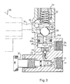
- FIG. 3 illustrates a preferred form of reactive pressure regulator for breathing equipment embodying the invention.
- the general construction of this regulator is as disclosed in GB-A-1 511 844. It comprises a body having an inlet port 21 adapted for connection to a high pressure breathing gas source such a 0.25 litre bottle charged with clean air at 207 ats. (providing about 52 litres of air at normal pressure).
- the inlet port 21 is connected to a valve chamber 22 housing a spring-loaded poppet 23 engaging a seat 24 surrounding a passage to an outlet port 25 in a reaction chamber 26.
- a reaction member 36 has an axial overpressure relief passage 36 a normally sealed by a valve member 36 b on the upper end of the poppet 23 and is exposed to pressure in chamber 26 and to a reaction load applied by a spring 32 and ball 35 and adjusted by screwcap 31.
- the pressure at outlet port 25 is determined by the load on reaction member 36 that at the set pressure allows the poppet 23 to close. Overpressure at the outlet port 25 and in the chamber 26 lifts the reaction member 36 away from the valve member 36 b to provide relief via the passage 36 a .
- the basic construction is modified, as shown, to provide for unloading of the reaction member 36 by insertion into the valve body of a trigger element in the form of a probe 34 to engage a follower 33 interposed between the spring 32 and the ball 35, so as to withdraw the spring load from the latter and thereby allow the poppet 23 to close under its own spring load.
- the probe 34 is ramped to accomplish displacement of the follower 33 on insertion, and has a detent notch to retain the probe in its fully inserted position, against inadvertent withdrawal.
- the probe 34 is conveniently provided on a face mask 38 as shown in outline, to provide for stowage of the latter and to ensure automatic withdrawal of the probe (to set the regulator to deliver breathing gas) by the act of removing the face mask from stowage for use. Moreover, such automatic switching of the regulator will ensure purging of the mask before its donning, particularly important if donning takes place while submerged.
- the regulator has a screwdown valve 37 to close the inlet during long term storage of the equipment.
- the valve 37 may be fitted internally with a pressure relief valve to control charging of the air storage bottle with the regulator in situ or to guard against the dangers of excessive stored air pressure rise in the storage bottle.
- the inlet port 18 of the demand valve of Figures 1 and 2 would be connected to the regulated pressure outlet port 25 of the pressure regulator of Figure 3 by a suitable flexible hose such as a nylon pipe of about 4mm OD.
- Equipment according to the invention may provide for several minutes breathing at a life support rate and yet be of such a size and weight as to allow its being stowed in a small pack suitable for attachment to an airman's flying suit or to a lifejacket, or to an aircraft seat.
Landscapes
- Health & Medical Sciences (AREA)
- Pulmonology (AREA)
- General Health & Medical Sciences (AREA)
- Business, Economics & Management (AREA)
- Emergency Management (AREA)
- Respiratory Apparatuses And Protective Means (AREA)
Applications Claiming Priority (2)
| Application Number | Priority Date | Filing Date | Title |
|---|---|---|---|
| GB9007020 | 1990-03-29 | ||
| GB9007020A GB9007020D0 (en) | 1990-03-29 | 1990-03-29 | Emergency breathing equipment |
Publications (2)
| Publication Number | Publication Date |
|---|---|
| EP0449532A2 true EP0449532A2 (fr) | 1991-10-02 |
| EP0449532A3 EP0449532A3 (en) | 1992-12-02 |
Family
ID=10673463
Family Applications (1)
| Application Number | Title | Priority Date | Filing Date |
|---|---|---|---|
| EP19910302532 Withdrawn EP0449532A3 (en) | 1990-03-29 | 1991-03-22 | Emergency breathing equipment |
Country Status (6)
| Country | Link |
|---|---|
| US (1) | US5275153A (fr) |
| EP (1) | EP0449532A3 (fr) |
| JP (1) | JPH0639050A (fr) |
| AU (1) | AU642481B2 (fr) |
| GB (1) | GB9007020D0 (fr) |
| NO (1) | NO911085L (fr) |
Cited By (4)
| Publication number | Priority date | Publication date | Assignee | Title |
|---|---|---|---|---|
| EP0695561A1 (fr) | 1994-08-03 | 1996-02-07 | F.X.K. Patents Limited | Equipement respiratoire |
| FR2761609A1 (fr) * | 1997-04-07 | 1998-10-09 | Gerard Carron | Appareil respiratoire de secours |
| WO2002036206A1 (fr) * | 2000-11-02 | 2002-05-10 | Nicholas John Foss | Appareil respiratoire |
| WO2008101302A1 (fr) * | 2007-02-23 | 2008-08-28 | Resmed Ltd | Valve à la demande pour un appareil de respiration |
Families Citing this family (19)
| Publication number | Priority date | Publication date | Assignee | Title |
|---|---|---|---|---|
| US5666945A (en) * | 1995-06-07 | 1997-09-16 | Salter Labs | Pneumatically-operated gas demand apparatus |
| US5660172A (en) * | 1995-09-22 | 1997-08-26 | Hatton; Norman E. | Auxiliary breathing apparatus and method |
| US5572989A (en) * | 1995-10-31 | 1996-11-12 | Johnson Worldwide Associates | Pressure equalizing mechanism for a diving mask |
| US5575277A (en) * | 1996-01-17 | 1996-11-19 | Johnson Worldwide Associates | Equaliztion system for a diving mask |
| US6067984A (en) * | 1997-10-14 | 2000-05-30 | Piper; Samuel David | Pulmonary modulator apparatus |
| US6427691B1 (en) * | 1999-07-09 | 2002-08-06 | Walter Jinotti | Medical valve |
| US6364161B1 (en) | 2000-09-27 | 2002-04-02 | Victor Equipment Company | Oxygen conserver |
| US6644313B2 (en) * | 2001-02-01 | 2003-11-11 | Fisher & Paykel Healthcare Limited | Breathing assistance apparatus |
| KR20030087439A (ko) * | 2002-05-10 | 2003-11-14 | 박상복 | 기체 공급기 |
| US20030236489A1 (en) * | 2002-06-21 | 2003-12-25 | Baxter International, Inc. | Method and apparatus for closed-loop flow control system |
| KR20040025317A (ko) * | 2002-09-19 | 2004-03-24 | 주식회사 환경과 미래 | 기체 공급기 |
| USD495049S1 (en) | 2003-06-24 | 2004-08-24 | Taga Medical Technologies, Inc | Oxygen conserving regulator |
| US20060086359A1 (en) * | 2004-10-22 | 2006-04-27 | Taga Medical Technologies, Inc. | Dual scale control knob for an oxygen conserving regulator |
| WO2006050384A2 (fr) * | 2004-11-01 | 2006-05-11 | Salter Labs | Systeme et procede permettant de conserver une alimentation en oxygene tout en maintenant la saturation |
| RU2286819C1 (ru) * | 2005-05-19 | 2006-11-10 | Сергей Яковлевич Барбулев | Устройство подачи воздуха в капюшон самоспасателя |
| KR100777756B1 (ko) | 2006-07-14 | 2007-11-29 | 주식회사 산청 | 산소의 자동공급 시스템 |
| US20110155771A1 (en) * | 2009-08-10 | 2011-06-30 | Brooks Dennis L | Method and apparatus for enabling smoother, faster discharge of fluid from containers |
| US20110132939A1 (en) * | 2009-08-10 | 2011-06-09 | Brooks Dennis L | Method and Apparatus for Enabling Smoother, Faster Discharge of Fluid from Containers |
| US8783251B2 (en) * | 2010-02-12 | 2014-07-22 | Piper Medical, Inc | Enhanced manually actuated pressure controlled modulator technology |
Family Cites Families (12)
| Publication number | Priority date | Publication date | Assignee | Title |
|---|---|---|---|---|
| GB719025A (en) * | 1952-01-28 | 1954-11-24 | Garrett Corp | Improvements in or relating to gas regulating apparatus |
| US3047001A (en) * | 1957-12-23 | 1962-07-31 | Bendix Corp | Respiratory apparatus |
| DE1104829B (de) * | 1959-05-11 | 1961-04-13 | Draegerwerk Ag | Druckgasatemschutzgeraet mit einem Druckminderer und einer Rueckzugsignalvorrichtung |
| GB938649A (en) * | 1962-04-19 | 1963-10-02 | Sierra Eng Co | Combination inhalator-exhalator valve |
| GB1224478A (en) * | 1967-11-29 | 1971-03-10 | Cyprane Ltd | Improvements in volatile anaesthetic vapourising apparatus |
| US3524464A (en) * | 1968-03-22 | 1970-08-18 | Automatic Sprinkler Corp | Pressure demand exhalation valve |
| GB1432171A (en) * | 1973-05-17 | 1976-04-14 | Jones W | Anaesthetic inflation valves |
| GB1511844A (en) * | 1975-05-15 | 1978-05-24 | Kay F | Gas pressure regulators |
| US4147176A (en) * | 1975-06-30 | 1979-04-03 | Christianson Raymond | Diaphragm assembly for the demand regulator of a breathing apparatus |
| US4082093A (en) * | 1977-04-27 | 1978-04-04 | Bourns, Inc. | Compensator valve |
| US4159717A (en) * | 1977-06-07 | 1979-07-03 | Under Sea Industries, Inc. | Antiset protector for second stage scuba regulators |
| US4606340A (en) * | 1983-07-14 | 1986-08-19 | Figgie International Inc. | Combined pressure compensating exhalation and anti-suffocation valve |
-
1990
- 1990-03-29 GB GB9007020A patent/GB9007020D0/en active Pending
-
1991
- 1991-03-19 NO NO91911085A patent/NO911085L/no unknown
- 1991-03-22 EP EP19910302532 patent/EP0449532A3/en not_active Withdrawn
- 1991-03-26 US US07/675,288 patent/US5275153A/en not_active Expired - Fee Related
- 1991-03-28 AU AU73876/91A patent/AU642481B2/en not_active Ceased
- 1991-03-29 JP JP9272791A patent/JPH0639050A/ja active Pending
Cited By (4)
| Publication number | Priority date | Publication date | Assignee | Title |
|---|---|---|---|---|
| EP0695561A1 (fr) | 1994-08-03 | 1996-02-07 | F.X.K. Patents Limited | Equipement respiratoire |
| FR2761609A1 (fr) * | 1997-04-07 | 1998-10-09 | Gerard Carron | Appareil respiratoire de secours |
| WO2002036206A1 (fr) * | 2000-11-02 | 2002-05-10 | Nicholas John Foss | Appareil respiratoire |
| WO2008101302A1 (fr) * | 2007-02-23 | 2008-08-28 | Resmed Ltd | Valve à la demande pour un appareil de respiration |
Also Published As
| Publication number | Publication date |
|---|---|
| US5275153A (en) | 1994-01-04 |
| AU7387691A (en) | 1991-10-03 |
| NO911085D0 (no) | 1991-03-19 |
| EP0449532A3 (en) | 1992-12-02 |
| NO911085L (no) | 1991-09-30 |
| JPH0639050A (ja) | 1994-02-15 |
| GB9007020D0 (en) | 1990-05-30 |
| AU642481B2 (en) | 1993-10-21 |
Similar Documents
| Publication | Publication Date | Title |
|---|---|---|
| US5275153A (en) | Demand valve having reaction load means and an insertable trigger element | |
| US4173986A (en) | Pressurized gas flow control valve and assembly thereof with reducer regulator | |
| EP1933946B1 (fr) | Masque respiratoire perfectionne et regulateur associe destine a un avion | |
| US4436090A (en) | Piston actuated, pilot valve operated breathing regulator | |
| US4499914A (en) | Selector valve for an aircraft on board oxygen generation system with high pressure oxygen backup | |
| US3762407A (en) | Survival support device | |
| CA1297377C (fr) | Systeme de survie pour l'equipage des avions | |
| US5701889A (en) | Oxygen breathing controller having a G-sensor | |
| EP2049390B1 (fr) | Dispositif actionné par la pression et système de respiration | |
| CA2255040C (fr) | Appareil respiratoire | |
| US4266539A (en) | Carbon dioxide scrubber and gas regenerator unit for a closed circuit rebreathing apparatus | |
| EP2010297A1 (fr) | Dispositifs, systèmes et procédés permettant le fonctionnement d'un appareil de respiration dans des modes multiples | |
| US5520170A (en) | Automatic resuscitator | |
| CA2824722A1 (fr) | Pulmocommande d'aeronef et methode de regulation de dilution | |
| CA1129303A (fr) | Respirateur a pression et a demande avec vanne automatique | |
| JPH0215223B2 (fr) | ||
| US4630605A (en) | Respirator control device | |
| US5351682A (en) | Breathing demand regulations | |
| US6796306B2 (en) | Respiratory apparatus with flow limiter | |
| NO812266L (no) | Pustehjelpventil. | |
| CA1091539A (fr) | Regulateur d'oxygene | |
| EP2237838A2 (fr) | Système de distribution d'oxygène d'urgence actionné mécaniquement | |
| EP0601098B1 (fr) | Ensemble de regulation de pression servant a alimenter un fluide sous pression a partir de conduits d'alimentation principal ou de secours | |
| EP0158498A2 (fr) | Appareil respiratoire à oxygène comprimé en circuit fermé | |
| EP0078644A2 (fr) | Régulateur de refoulement de gaz respiratoir |
Legal Events
| Date | Code | Title | Description |
|---|---|---|---|
| PUAI | Public reference made under article 153(3) epc to a published international application that has entered the european phase |
Free format text: ORIGINAL CODE: 0009012 |
|
| AK | Designated contracting states |
Kind code of ref document: A2 Designated state(s): AT BE CH DE DK ES FR GB GR IT LI LU NL SE |
|
| PUAL | Search report despatched |
Free format text: ORIGINAL CODE: 0009013 |
|
| AK | Designated contracting states |
Kind code of ref document: A3 Designated state(s): AT BE CH DE DK ES FR GB GR IT LI LU NL SE |
|
| 17P | Request for examination filed |
Effective date: 19930315 |
|
| 17Q | First examination report despatched |
Effective date: 19950123 |
|
| STAA | Information on the status of an ep patent application or granted ep patent |
Free format text: STATUS: THE APPLICATION IS DEEMED TO BE WITHDRAWN |
|
| 18D | Application deemed to be withdrawn |
Effective date: 19950603 |