EP0449698A1 - Verschlusskappe eines schlauchförmigen Organs, insbesondere für ein teleskopisches System von Kardanantriebswellen - Google Patents
Verschlusskappe eines schlauchförmigen Organs, insbesondere für ein teleskopisches System von Kardanantriebswellen Download PDFInfo
- Publication number
- EP0449698A1 EP0449698A1 EP91400715A EP91400715A EP0449698A1 EP 0449698 A1 EP0449698 A1 EP 0449698A1 EP 91400715 A EP91400715 A EP 91400715A EP 91400715 A EP91400715 A EP 91400715A EP 0449698 A1 EP0449698 A1 EP 0449698A1
- Authority
- EP
- European Patent Office
- Prior art keywords
- capsule
- bowl
- axial
- groove
- concave housing
- Prior art date
- Legal status (The legal status is an assumption and is not a legal conclusion. Google has not performed a legal analysis and makes no representation as to the accuracy of the status listed.)
- Granted
Links
Images


Classifications
-
- F—MECHANICAL ENGINEERING; LIGHTING; HEATING; WEAPONS; BLASTING
- F16—ENGINEERING ELEMENTS AND UNITS; GENERAL MEASURES FOR PRODUCING AND MAINTAINING EFFECTIVE FUNCTIONING OF MACHINES OR INSTALLATIONS; THERMAL INSULATION IN GENERAL
- F16D—COUPLINGS FOR TRANSMITTING ROTATION; CLUTCHES; BRAKES
- F16D3/00—Yielding couplings, i.e. with means permitting movement between the connected parts during the drive
- F16D3/16—Universal joints in which flexibility is produced by means of pivots or sliding or rolling connecting parts
- F16D3/26—Hooke's joints or other joints with an equivalent intermediate member to which each coupling part is pivotally or slidably connected
- F16D3/38—Hooke's joints or other joints with an equivalent intermediate member to which each coupling part is pivotally or slidably connected with a single intermediate member with trunnions or bearings arranged on two axes perpendicular to one another
- F16D3/382—Hooke's joints or other joints with an equivalent intermediate member to which each coupling part is pivotally or slidably connected with a single intermediate member with trunnions or bearings arranged on two axes perpendicular to one another constructional details of other than the intermediate member
- F16D3/387—Fork construction; Mounting of fork on shaft; Adapting shaft for mounting of fork
-
- F—MECHANICAL ENGINEERING; LIGHTING; HEATING; WEAPONS; BLASTING
- F16—ENGINEERING ELEMENTS AND UNITS; GENERAL MEASURES FOR PRODUCING AND MAINTAINING EFFECTIVE FUNCTIONING OF MACHINES OR INSTALLATIONS; THERMAL INSULATION IN GENERAL
- F16D—COUPLINGS FOR TRANSMITTING ROTATION; CLUTCHES; BRAKES
- F16D3/00—Yielding couplings, i.e. with means permitting movement between the connected parts during the drive
- F16D3/02—Yielding couplings, i.e. with means permitting movement between the connected parts during the drive adapted to specific functions
- F16D3/06—Yielding couplings, i.e. with means permitting movement between the connected parts during the drive adapted to specific functions specially adapted to allow axial displacement
Definitions
- the present invention relates to a closure cap for a tubular member constituting in particular a first element for a telescopic system of cardan shafts, this capsule being intended to be fixed by peripheral immobilization means at one of the ends.
- an axial bore of said member to constitute with one end of a second element of said telescopic system, mounted to slide axially in said first element, a sealed sliding chamber with variable volume.
- closure plugs currently fitted to Cardan transmissions, and which are constituted by a flat and symmetrical circular metal washer, cut from a sheet metal blank, and which has a central hole around which are provided several peripheral or satellite holes , equidistant from each other in circumferential direction and closed using a rubber valve plugged in or snapped elastically into the central hole, and capable of putting the sealed sliding chamber in communication with the outside, during a overpressure escaping through the satellite holes by overcoming the adequately chosen resistance of opening the valve.
- Such a capsule is initially centered with a radial clearance in a recess of the end of the tubular member, and a crimping by points or circular is carried out on the periphery of this recess by deformation of material of said member.
- crimping by points limits the axial strength of the assembly because, in fact, during the handling, transport or assembly of the transmission on the vehicle, untimely relative movements of the telescopic elements can shake the crimping of the capsule. and go to the rupture of the deformed parts resulting from the crimping and causing the loss of the capsule.
- the object of the present invention is to remedy these numerous drawbacks arising from the current technique.
- the invention proposes a capsule for closing a tubular member constituting in particular a first element for telescopic system of cardan shafts, said capsule being intended to be fixed by peripheral immobilization means to one of the ends of an axial bore of said member to constitute with one end of a second element of said telescopic system, mounted to slide axially in said first element, a sealed sliding chamber with variable volume.
- the peripheral immobilization means consist of an axial circular peripheral rim obtained integrally with the capsule to form a cylindrical cup capable of engaging in a peripheral axial retaining groove formed inside said bore of said tubular member, near the corresponding end of the latter.
- the present invention also relates to the characteristics below considered in isolation or in combination.
- the rim of the bowl is expanded, substantially radially outward, in the groove of the tubular member by discharge of material from the capsule, and not from the tubular member, during a crimping operation, to be retained there axially by a shoulder of said groove. This ensures excellent axial strength of the capsule and good sealing of the lubricant, without weakening the tubular member.
- the axial rim of the bowl has a profile substantially corresponding to that of the groove, in which it engages elastically until it snaps behind a shoulder for retaining axial said groove.
- the tightness ensured by this variant may be a little less good than in the preferred embodiment, but this is compensated by an economy of means of implementation and assembly of the capsule.
- such an embodiment has the advantage of not requiring any crimping device, and, within certain limits, the capsule can even be put in place by hand.
- the groove of the tubular member is formed on the internal peripheral wall of a recess arranged in the corresponding end part of the bore of the tubular member, and the bottom of which constitutes a radial shoulder on which the bowl comes into axial abutment, during mounting of the capsule, in order to improve sealing.
- this tightness and the axial strength of the capsule are further improved if, in addition, an annular part of a cylindrical bowl, located between its rim housed in the groove and its base for connection to the central part of the capsule, is deformed in expansion. substantially radial towards the outside against the internal peripheral wall of the recess, when the capsule is mounted in the bore defined by this recess.
- the groove is produced according to a slope, in its part directed towards said corresponding end of the bore of the tubular member, and according to a depth, capable of ensuring the axial retention of said capsule after implementation.
- the capsule is obtained from a stamped sheet metal blank deformed in its central part, to form a concave housing capable of accommodating a head of a rubber pressure relief valve, snapped in a central hole made in the bottom of said concave housing of the capsule and in communication with the sliding chamber of the telescopic system, so that the head of the valve sealingly plugs holes distributed around the central hole and also formed in the bottom concave housing.
- valve is protected against any attack by the lubrication clips, during the lubrication operations of the assembly.
- the expansion of the capsule bowl in the groove and its contact in general with the recess ensures effective sealing eliminating any loss of lubricant both during rotation only during transmission stoppage.
- the central part of said capsule constituted by the concave housing is connected to the base of the bowl by a convex intermediate part, capable of constituting a reserve of lubricant, in the minimum sliding position of the telescopic system.
- the bottom and the peripheral edge of the concave housing of the capsule are offset axially towards the corresponding end of said bore with respect respectively to the base and at the free end edge of the cylindrical bowl.
- the central part of the capsule constituted by the housing concave, or connected to the base of the bowl of the capsule by a flat and radial intermediate part, extending substantially perpendicular to the axis of the cylindrical bowl.
- the concave housing of the capsule is of a shallow axial depth relative to the axial dimension of the valve, and that the peripheral edge of the concave housing is close to the base of the cylindrical cup of the capsule, so that the valve head can be housed in the concave housing and in the cylindrical bowl.
- the bottom of the concave housing advantageously has the shape of a spherical cap centered on the axis of the central hole.
- the elimination of the crimping of the capsule by deformation of the material of the jaw and its replacement by the delivery of the capsule in a recess provided with a groove not only improves the axial holding. of the capsule itself, but also the fatigue strength, under alternating torque, of the jaw, some of which ruptures are initialized from the crimping points.
- the load required for encapsulation according to the invention varies from 2000 to 5000 daN depending on the dimensioning, while for crimping by deformation of material, as known, it is of the order of 3000 to 8000 daN.
- this capping ensures, under identical test conditions, a static and dynamic axial resistance, approximately three times greater than that obtained by crimping by points of the prior art.
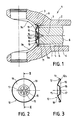
- a telescopic system 1 partially represented consists of a first element 2, constituted by a jaw 3 representing a part of articulation with Cardan joint, extended by a tubular member or sheath 4 , whose axial bore 5 comprises internal longitudinal grooves 6 cooperating in sliding with corresponding external longitudinal grooves 7 of a second element 8 of the telescopic system, these grooves 7 being formed on a cylindrical end piece 9 of said second element 8, suitable for slide in the sheath 4 of the first element 2.
- the assembly thus formed is provided, at one of its ends (not shown), with a sliding seal, disposed between the first and second elements 2, 8 of the telescopic system, and closed at its other end, at the outlet of the bore 5 between the ears 3a, 3b of the jaw 3, by a capsule 10 salt on the invention, defining with the end 9a of the cylindrical end piece 9, a sealed sliding chamber 11, with variable volume.
- the capsule 10, according to the invention is obtained for example from a sheet of steel sheet cut circularly, then stamped to obtain a cylindrical bowl 12 delimited peripherally by a axial rim 13 obtained with the cup during the same stamping operation and able to engage in a peripheral axial retaining groove 14, machined in the internal wall of the corresponding end part of the bore 5 of the sheath 4, to constitute, in cooperation with said groove 14, peripheral immobilization means of said capsule at the end of the sheath 4.
- the bowl 10, as shown in Figure 1 further comprises, obtained during the stamping operation, a central deformation constituting a concave housing 15, the concavity of which is turned towards the outside of the bore 5 , and capable of accommodating the head of a rubber pressure relief valve 16, plugged in or snapped elastically by a central rod 16a of frustoconical shape in a central hole 17 formed in the bottom of the concave housing 15 of the capsule 10, and surrounded by peripheral or satellite holes 18 also formed in the bottom of the housing 15.
- the valve head is of an external diameter sufficient for it to cover the satellite holes 18, equidistant from each other in circumferential direction around the central hole 17 and at number six in this example.
- the valve 16 thus seals, except in the event of overpressures, which are discharged through the holes 18 by lifting the head of the valve 16.
- the concave housing 15 thus defined is connected to the base 12a of the bowl 12 by a convex intermediate part 19, the convexity of which faces outwards from the bore 5, and capable of constituting a reserve of lubricant, in the position minimum sliding of the telescopic system, as shown in Figure 1.
- the capsule 10 is coated with an anti-corrosion protection of the zinc-chromating type, for example.
- the groove 14 of the sleeve 4 is formed in the internal peripheral wall of a recess 20 produced in the corresponding end part of the bore 5 of said sleeve 4, and the bottom 21 of which constitutes a radial shoulder on which comes into axial abutment the base 12a of the bowl 12.
- This recess 20 thus consists of a "front” recess 20a, between the groove 14 and the corresponding end of the bore 5 and the sleeve 4, and a “rear” recess 20b, between the groove 14 and the bottom 21 of the recess 20.
- the groove 14 is produced with a slope defined by the angle " ⁇ " towards the corresponding end of the bore 5, with a depth "g” and at a distance "h” from the bottom 21 of the recess 20 (see FIG. 4 ).
- the establishment of the capsule 10 is carried out as follows.
- the capsule 10 is introduced into the recess 20 and abutted on the bottom 21 of the latter.
- the radial clearance "J" between the outside diameter of the bowl 12 and the rear recess 20b is reduced to the minimum allowable achievable by standard economic manufacturing means.
- the axial position of the end 13a of the rim 13 of the bowl 12 relative to the axial position at the distance "h" from the groove 14 with respect to the bottom 21 of the recess 20 must always be such that this end 13a is located in front of the slope at the angle " ⁇ ".
- Lh where L is the axial dimension of the cylindrical bowl 12, is chosen as a function of the profile and the depth "g" of the groove 14 as well as the dimensioning of the capsule 10, and the slope of the groove 14 thus defines an axial retaining shoulder 14a.
- the capsule 10 thus put in place is crimped in the following manner (FIG. 5).
- the punch 22 Under a load F, variable according to the types and dimensions of capsules 10, the punch 22 is moves by a stroke C by deforming and driving the rim 13 substantially radially outward, on the one hand, in the groove 14 along the slope " ⁇ ", and, on the other hand, in the rear casing 20b , thereby removing the mounting set "J".
- the punch 22 is stopped at a height "S" from the bottom 21 of the recess 20, by a tool design "refusal" for example.
- the variant embodiment shown in FIG. 6 is particularly suitable for very short Cardan transmissions and designed for operating angularities of the order of 7 °, which restricts the space available, necessary and sufficient, between a possible lubricator. central and the valve 16, to use a capsule according to the invention, as described above.
- the solution represented in FIG. 6 solves this problem, by proposing a capsule 30 always having a central part in concave housing 31, capable of protecting the valve 16 in the same manner as previously, but in this case, the peripheral edge of the concave housing 31 is connected to the base of the bowl 32 of the capsule 30 by a flat radial intermediate ring 34, substantially perpendicular to the axis of the cylindrical bowl 32 rather than convex.
- a recess 35 is produced in the cylindrical end piece 9 of the telescopic element 8, either by forging, casting or machining, which makes it possible, on the one hand, to house the central part 31 of the capsule 30, and, on the other hand, to ensure a minimum reserve of lubricant necessary for the functioning of the telescopic system.
- the variant embodiment shown in FIG. 7 is particularly suited to the light ranges of Cardan transmissions offering very small dimensions.
- the external diameter of the external splines of the cylindrical end piece 9 is practically equal to the external diameter of the head of the rubber valve 16.
- This embodiment proposes, to solve this problem of space, a capsule 40, the part of which central in concave housing 41 is in the immediate vicinity and almost directly attached by its peripheral edge to the base of the cylindrical bowl 42, which thus naturally becomes a protective well for the valve 16.
- the encapsulation by delivery remains of course, the same as the one described above.
- a central machining recess 43 produced during the operating range of the sliding end piece 8, provides housing for the conical retaining part 16a of the valve 16.
- the axial depth of the cylindrical bowl 42 is added to the shallow axial depth of the concave housing 41, which alone is much less than the axial dimension of the head of the valve 16, to define a sufficient recess in order to accommodate completely the head of this valve 16.
- the bottom of the concave housing 15 has the shape of a spherical cap centered on the axis of the central hole 17.
- the bottom and the peripheral edge of the concave housing 15 are offset axially towards the corresponding end of the bore 5 or of the recess 20, or towards the outside of the latter, relative to the base 12a and the free end edge of the rim 13 of the cylindrical cup 12 of the capsule respectively.
- the capsule is preferably obtained by a single stamping operation on a blank of circular metal sheet.
- the immobilization of the capsule can be ensured by means other than crimping, for example by giving the axial rim 13 of the cup 12 a profile substantially corresponding to that of the groove 14, in which it engages elastically until it clicks behind the shoulder 14a of axial retention, of said groove 14.
Landscapes
- Engineering & Computer Science (AREA)
- General Engineering & Computer Science (AREA)
- Mechanical Engineering (AREA)
- Sealing Devices (AREA)
- Percussion Or Vibration Massage (AREA)
Applications Claiming Priority (2)
| Application Number | Priority Date | Filing Date | Title |
|---|---|---|---|
| FR9004040 | 1990-03-29 | ||
| FR9004040A FR2660378B1 (fr) | 1990-03-29 | 1990-03-29 | Capsule d'obturation d'un organe tubulaire, notamment pour systeme telescopique d'arbres de transmission a cardan. |
Publications (2)
| Publication Number | Publication Date |
|---|---|
| EP0449698A1 true EP0449698A1 (de) | 1991-10-02 |
| EP0449698B1 EP0449698B1 (de) | 1994-08-03 |
Family
ID=9395250
Family Applications (1)
| Application Number | Title | Priority Date | Filing Date |
|---|---|---|---|
| EP19910400715 Expired - Lifetime EP0449698B1 (de) | 1990-03-29 | 1991-03-15 | Verschlusskappe eines schlauchförmigen Organs, insbesondere für ein teleskopisches System von Kardanantriebswellen |
Country Status (4)
| Country | Link |
|---|---|
| EP (1) | EP0449698B1 (de) |
| DE (2) | DE69103184T2 (de) |
| ES (1) | ES2027615T3 (de) |
| FR (1) | FR2660378B1 (de) |
Cited By (4)
| Publication number | Priority date | Publication date | Assignee | Title |
|---|---|---|---|---|
| WO1996030665A1 (en) * | 1995-03-28 | 1996-10-03 | Rockwell International Corporation | Snap-in plug for a universal joint-yoke |
| US5716276A (en) * | 1996-09-03 | 1998-02-10 | Dana Corporation | Yoke shaft for a vehicular driveshaft assembly |
| EP0852300A3 (de) * | 1996-12-20 | 1998-09-30 | SKF INDUSTRIE S.p.A. | Einrichtung zur lösbaren Verbindung eines Gleichlaufgelenks mit einer Nabe |
| CN104806754A (zh) * | 2015-04-28 | 2015-07-29 | 浙江龙虎锻造有限公司 | 汽车用非滑动叉 |
Families Citing this family (2)
| Publication number | Priority date | Publication date | Assignee | Title |
|---|---|---|---|---|
| US8882602B2 (en) | 2013-03-08 | 2014-11-11 | Dana Automotive Systems Group, Llc | Slip yoke assembly |
| US8734261B1 (en) | 2013-03-08 | 2014-05-27 | Dana Automotive Systems Group, Llc | Slip yoke assembly |
Citations (6)
| Publication number | Priority date | Publication date | Assignee | Title |
|---|---|---|---|---|
| US1917988A (en) * | 1932-02-04 | 1933-07-11 | New Departure Mfg Co | Bearing and guard therefor |
| US2510362A (en) * | 1944-11-20 | 1950-06-06 | Borg Warner | Seal |
| US2650484A (en) * | 1947-05-29 | 1953-09-01 | Vickers Inc | Power transmission |
| FR2183395A5 (de) * | 1972-05-05 | 1973-12-14 | Glaenzer Spicer Sa | |
| US4114898A (en) * | 1976-03-23 | 1978-09-19 | Garlock Inc. | Oil seal with permanently deformable locking member |
| FR2526760A1 (fr) * | 1982-05-14 | 1983-11-18 | Dana Corp | Bouchon d'obturation de fourche cannelee coulissante |
-
1990
- 1990-03-29 FR FR9004040A patent/FR2660378B1/fr not_active Expired - Fee Related
-
1991
- 1991-03-15 EP EP19910400715 patent/EP0449698B1/de not_active Expired - Lifetime
- 1991-03-15 ES ES91400715T patent/ES2027615T3/es not_active Expired - Lifetime
- 1991-03-15 DE DE1991603184 patent/DE69103184T2/de not_active Expired - Fee Related
- 1991-03-15 DE DE1991400715 patent/DE449698T1/de active Pending
Patent Citations (6)
| Publication number | Priority date | Publication date | Assignee | Title |
|---|---|---|---|---|
| US1917988A (en) * | 1932-02-04 | 1933-07-11 | New Departure Mfg Co | Bearing and guard therefor |
| US2510362A (en) * | 1944-11-20 | 1950-06-06 | Borg Warner | Seal |
| US2650484A (en) * | 1947-05-29 | 1953-09-01 | Vickers Inc | Power transmission |
| FR2183395A5 (de) * | 1972-05-05 | 1973-12-14 | Glaenzer Spicer Sa | |
| US4114898A (en) * | 1976-03-23 | 1978-09-19 | Garlock Inc. | Oil seal with permanently deformable locking member |
| FR2526760A1 (fr) * | 1982-05-14 | 1983-11-18 | Dana Corp | Bouchon d'obturation de fourche cannelee coulissante |
Cited By (6)
| Publication number | Priority date | Publication date | Assignee | Title |
|---|---|---|---|---|
| WO1996030665A1 (en) * | 1995-03-28 | 1996-10-03 | Rockwell International Corporation | Snap-in plug for a universal joint-yoke |
| US5716276A (en) * | 1996-09-03 | 1998-02-10 | Dana Corporation | Yoke shaft for a vehicular driveshaft assembly |
| EP0852300A3 (de) * | 1996-12-20 | 1998-09-30 | SKF INDUSTRIE S.p.A. | Einrichtung zur lösbaren Verbindung eines Gleichlaufgelenks mit einer Nabe |
| US6139216A (en) * | 1996-12-20 | 2000-10-31 | Skf Industrie S.P.A. | Reversible device for locking a constant-velocity joint to a hub |
| CN104806754A (zh) * | 2015-04-28 | 2015-07-29 | 浙江龙虎锻造有限公司 | 汽车用非滑动叉 |
| CN104806754B (zh) * | 2015-04-28 | 2017-11-07 | 浙江龙虎锻造有限公司 | 汽车用非滑动叉 |
Also Published As
| Publication number | Publication date |
|---|---|
| DE69103184T2 (de) | 1995-03-23 |
| DE449698T1 (de) | 1992-04-30 |
| DE69103184D1 (de) | 1994-09-08 |
| ES2027615T1 (es) | 1992-06-16 |
| FR2660378B1 (fr) | 1995-02-17 |
| ES2027615T3 (es) | 1994-10-16 |
| FR2660378A1 (fr) | 1991-10-04 |
| EP0449698B1 (de) | 1994-08-03 |
Similar Documents
| Publication | Publication Date | Title |
|---|---|---|
| EP2689110B1 (de) | Absperrvorrichtung mit automatisch aktivierbarer verriegelung | |
| EP1170157B1 (de) | Axialwälzlager für eine Fahrzeugaufhängung mit Rückhaltemittel | |
| EP0755488B1 (de) | Hydraulisch betätigtes ausrücklager für kraftfahrzeugkupplung mit membranfeder | |
| EP2926028B1 (de) | Klemmbarer verschluss mit einer deflektorschürze für ein lenkungsgehäuse | |
| EP1146244B1 (de) | Kupplungsausrücklager | |
| EP0635651B1 (de) | Lageranordnung für eine rotierende Welle einer Scheibenwischeranlage | |
| EP1612443A1 (de) | Kupplungsausrücklager und Verfahren zu seiner Herstellung. | |
| EP0561704B1 (de) | Axialwälzlager für Fahrzeugaufhängung und sein Montageverfahren | |
| EP0449698B1 (de) | Verschlusskappe eines schlauchförmigen Organs, insbesondere für ein teleskopisches System von Kardanantriebswellen | |
| CA2738094A1 (fr) | Composant pour le forage et l'exploitation des puits d'hydrocarbures | |
| WO2000036326A1 (fr) | Element tubulaire de conduite comportant une partie longitudinale rigide et une partie longitudinale souple en une seule piece | |
| FR2561333A1 (fr) | Couvercle tulipe pour joint homocinetique tripode, et joint le comportant | |
| CH627237A5 (de) | ||
| EP0891496B1 (de) | Übertragungsgelenkkreuz und entsprechendes übertragungsgelenk | |
| EP1941201B1 (de) | Verbindungsvorrichtung mit geschweisstem körper | |
| FR3103018A1 (fr) | Butée de suspension de véhicule automobile | |
| FR2516878A1 (fr) | Pivot d'essuie-glace | |
| EP1155932A1 (de) | Lager zur Führung und axialen Positionierung einer rotierenden Welle | |
| EP3749539B1 (de) | Einfüllbaugruppe für kraftstoff oder reinigungsmittel eines kraftfahrzeugs | |
| FR2791739A1 (fr) | Verin hydraulique pour un equipement hydraulique de vehicule | |
| FR3089271A1 (fr) | Soufflet de protection et joint de transmission équipé d'un tel soufflet | |
| FR2714125A1 (fr) | Dispositif de montage d'une rotule sur une pièce de structure. | |
| FR2795467A1 (fr) | Ensemble de croisillon pour joint de transmission et joint de transmission correspondant | |
| FR3159558A1 (fr) | Butée tournante de suspension pourvue d’un joint d’étanchéité encastré | |
| EP3865728A1 (de) | Axial begrenztes antivibrationsgelenk |
Legal Events
| Date | Code | Title | Description |
|---|---|---|---|
| PUAI | Public reference made under article 153(3) epc to a published international application that has entered the european phase |
Free format text: ORIGINAL CODE: 0009012 |
|
| AK | Designated contracting states |
Kind code of ref document: A1 Designated state(s): DE ES GB IT |
|
| 17P | Request for examination filed |
Effective date: 19911111 |
|
| ITCL | It: translation for ep claims filed |
Representative=s name: JACOBACCI CASETTA & PERANI S.P.A. |
|
| GBC | Gb: translation of claims filed (gb section 78(7)/1977) | ||
| DET | De: translation of patent claims | ||
| 17Q | First examination report despatched |
Effective date: 19921217 |
|
| GRAA | (expected) grant |
Free format text: ORIGINAL CODE: 0009210 |
|
| AK | Designated contracting states |
Kind code of ref document: B1 Designated state(s): DE ES GB IT |
|
| REF | Corresponds to: |
Ref document number: 69103184 Country of ref document: DE Date of ref document: 19940908 |
|
| REG | Reference to a national code |
Ref country code: ES Ref legal event code: FG2A Ref document number: 2027615 Country of ref document: ES Kind code of ref document: T3 |
|
| ITF | It: translation for a ep patent filed | ||
| GBT | Gb: translation of ep patent filed (gb section 77(6)(a)/1977) |
Effective date: 19941103 |
|
| PLBE | No opposition filed within time limit |
Free format text: ORIGINAL CODE: 0009261 |
|
| 26N | No opposition filed | ||
| PGFP | Annual fee paid to national office [announced via postgrant information from national office to epo] |
Ref country code: ES Payment date: 20000313 Year of fee payment: 10 |
|
| PGFP | Annual fee paid to national office [announced via postgrant information from national office to epo] |
Ref country code: GB Payment date: 20000315 Year of fee payment: 10 |
|
| PGFP | Annual fee paid to national office [announced via postgrant information from national office to epo] |
Ref country code: DE Payment date: 20000519 Year of fee payment: 10 |
|
| PG25 | Lapsed in a contracting state [announced via postgrant information from national office to epo] |
Ref country code: GB Free format text: LAPSE BECAUSE OF NON-PAYMENT OF DUE FEES Effective date: 20010315 |
|
| PG25 | Lapsed in a contracting state [announced via postgrant information from national office to epo] |
Ref country code: ES Free format text: LAPSE BECAUSE OF NON-PAYMENT OF DUE FEES Effective date: 20010316 |
|
| GBPC | Gb: european patent ceased through non-payment of renewal fee |
Effective date: 20010315 |
|
| PG25 | Lapsed in a contracting state [announced via postgrant information from national office to epo] |
Ref country code: DE Free format text: LAPSE BECAUSE OF NON-PAYMENT OF DUE FEES Effective date: 20020101 |
|
| REG | Reference to a national code |
Ref country code: ES Ref legal event code: FD2A Effective date: 20030203 |
|
| PG25 | Lapsed in a contracting state [announced via postgrant information from national office to epo] |
Ref country code: IT Free format text: LAPSE BECAUSE OF NON-PAYMENT OF DUE FEES;WARNING: LAPSES OF ITALIAN PATENTS WITH EFFECTIVE DATE BEFORE 2007 MAY HAVE OCCURRED AT ANY TIME BEFORE 2007. THE CORRECT EFFECTIVE DATE MAY BE DIFFERENT FROM THE ONE RECORDED. Effective date: 20050315 |