EP0449715B1 - Einrichtung zur Kodierung/Dekodierung von Bildsignalen - Google Patents
Einrichtung zur Kodierung/Dekodierung von Bildsignalen Download PDFInfo
- Publication number
- EP0449715B1 EP0449715B1 EP91400794A EP91400794A EP0449715B1 EP 0449715 B1 EP0449715 B1 EP 0449715B1 EP 91400794 A EP91400794 A EP 91400794A EP 91400794 A EP91400794 A EP 91400794A EP 0449715 B1 EP0449715 B1 EP 0449715B1
- Authority
- EP
- European Patent Office
- Prior art keywords
- image
- coding
- blocks
- decoding
- transformation
- Prior art date
- Legal status (The legal status is an assumption and is not a legal conclusion. Google has not performed a legal analysis and makes no representation as to the accuracy of the status listed.)
- Expired - Lifetime
Links
- 230000015654 memory Effects 0.000 claims description 49
- 230000009466 transformation Effects 0.000 claims description 38
- 238000013139 quantization Methods 0.000 claims description 22
- 230000005540 biological transmission Effects 0.000 claims description 21
- 101150062184 DSP4 gene Proteins 0.000 claims description 15
- SDJLVPMBBFRBLL-UHFFFAOYSA-N dsp-4 Chemical compound ClCCN(CC)CC1=CC=CC=C1Br SDJLVPMBBFRBLL-UHFFFAOYSA-N 0.000 claims description 15
- 230000002441 reversible effect Effects 0.000 claims description 13
- 239000013598 vector Substances 0.000 claims description 11
- 238000006073 displacement reaction Methods 0.000 claims description 10
- 230000002457 bidirectional effect Effects 0.000 claims description 9
- 101100388212 Arabidopsis thaliana DSP3 gene Proteins 0.000 claims description 6
- 101100388215 Arabidopsis thaliana DSP5 gene Proteins 0.000 claims description 5
- 230000006870 function Effects 0.000 claims description 3
- 238000012805 post-processing Methods 0.000 claims description 3
- 101150115013 DSP1 gene Proteins 0.000 description 12
- 101150052726 DSP2 gene Proteins 0.000 description 12
- 238000011002 quantification Methods 0.000 description 11
- 238000010586 diagram Methods 0.000 description 10
- 230000033001 locomotion Effects 0.000 description 9
- 238000000034 method Methods 0.000 description 8
- 238000012545 processing Methods 0.000 description 8
- 230000008569 process Effects 0.000 description 6
- 230000006835 compression Effects 0.000 description 4
- 238000007906 compression Methods 0.000 description 4
- 238000012544 monitoring process Methods 0.000 description 2
- 230000009467 reduction Effects 0.000 description 2
- 241000861223 Issus Species 0.000 description 1
- 238000004364 calculation method Methods 0.000 description 1
- 230000008859 change Effects 0.000 description 1
- 238000006243 chemical reaction Methods 0.000 description 1
- 238000004891 communication Methods 0.000 description 1
- 238000000354 decomposition reaction Methods 0.000 description 1
- 230000000694 effects Effects 0.000 description 1
- 238000001914 filtration Methods 0.000 description 1
- 230000004907 flux Effects 0.000 description 1
- 230000002123 temporal effect Effects 0.000 description 1
- 238000011282 treatment Methods 0.000 description 1
Images


Classifications
-
- H—ELECTRICITY
- H04—ELECTRIC COMMUNICATION TECHNIQUE
- H04N—PICTORIAL COMMUNICATION, e.g. TELEVISION
- H04N19/00—Methods or arrangements for coding, decoding, compressing or decompressing digital video signals
- H04N19/42—Methods or arrangements for coding, decoding, compressing or decompressing digital video signals characterised by implementation details or hardware specially adapted for video compression or decompression, e.g. dedicated software implementation
- H04N19/423—Methods or arrangements for coding, decoding, compressing or decompressing digital video signals characterised by implementation details or hardware specially adapted for video compression or decompression, e.g. dedicated software implementation characterised by memory arrangements
-
- H—ELECTRICITY
- H04—ELECTRIC COMMUNICATION TECHNIQUE
- H04N—PICTORIAL COMMUNICATION, e.g. TELEVISION
- H04N19/00—Methods or arrangements for coding, decoding, compressing or decompressing digital video signals
- H04N19/60—Methods or arrangements for coding, decoding, compressing or decompressing digital video signals using transform coding
- H04N19/61—Methods or arrangements for coding, decoding, compressing or decompressing digital video signals using transform coding in combination with predictive coding
Definitions
- the present invention relates to a device for coding-decoding image signals.
- This invention relates to a device capable of processing real-time information signals of the sequential type, such as video signals, with the aim of compressing the volume of data necessary to represent the corresponding image, in order to transmit it with a bit rate. minimum binary using a transmission network.
- the device according to the invention is particularly applicable in television, videoconferencing or videophone. It can also be applied to slowly varying images such as remote monitoring.
- inter-image coding a first known type of coding
- coding by estimation of movement
- coding by estimation of movement consists in anticipating movement in the image by estimating an image in view of the previous image and in transmitting only information relating to the difference between this estimated image and the image actually received.
- the image coding system comprises a transformation means for applying a transformation operator to said image.
- This transformation operation translates the image of the spatial domain into a so-called frequency domain.
- the transformation operation can precede or follow the interimage coding or by motion estimation applied to the image.
- This transmission moreover consists in the case of coding by estimation of movement to be transmitted, for each block or movement, a displacement vector indicating the displacement of the block between the previous image and the current image. It is usual to decompose images into identical blocks of commonly used size such as 8 x 8 pixels, 16 x 16 pixels and sometimes 32 x 32 pixels. The compression factor is better the larger the blocks, but the compression gain is lower when going from 16 to 32 pixels and when going from 8 to 16 pixels.
- a conventional coder-decoder comprises a coding channel CODi, DCODi to reduce the bit rate of an image i to be transmitted over the network TR and a decoding channel DCODj to receive and decode the signal corresponding to a remote image j transmitted by this network TR.
- the conventional coding-decoding devices as represented in FIG. 1 make it possible to implement hybrid algorithms (that is to say algorithms which combine several image compression techniques, namely a prediction-transformation algorithm ), but are unfortunately cumbersome due to the processing complexity required by such algorithms.
- the aim of the coding-decoding device according to the invention is to remedy this drawback. It also makes it possible to better distribute the processing operations in order to reduce the computational loads of certain circuits.
- the transformation and reverse transformation means are produced by the same device and, in the same way, the quantization and inverse quantization means are also produced by the same device, so that the decoding is carried out by the coder, which contributes to further reducing the size of the coding-decoding device according to the invention.
- the multiprocessor system also comprises a fourth and a fifth image memories, these memories playing respectively a role identical to the first and second memories, the duplication making it possible to avoid the conflicts of access between the first and third processors .
- the multiprocessor system comprises a fifth signal processor for performing post-processing on the data originating from the third image memory and a sixth image memory for storing this data.
- the coding-decoding device further comprises an analog / digital converter for the local image signal to be transmitted, followed by a two-dimensional filter and a digital / analog converter for the data corresponding to the signal received from distant image.
- FIG. 1 shows the coding-decoding principle diagram according to the prior art.
- a coder-decoder according to the prior art comprises a coding channel CODi for the image signal i coming from a video input and intended to be transmitted by a transmission network TR. This channel also includes a loop in which is placed a decoder DCODi of the image i.
- the codec-decoder also comprises a decoding channel DCODj of the images transmitted j by the transmission network TR and intended to be displayed, the image signal being taken from the video output of this decoding channel.
- the term “local image” will be understood to mean the image applied to the video input of the coding channel and intended to be transmitted in order to be viewed at the end of transmission.
- the term “distant image” or “distant image signal” will be understood to mean the signal sent by another coding-decoding means and transmitted by the transmission network so that, at the end of processing, be at the video output.
- FIG. 2 therefore represents the block diagram of an encoder-decoder according to the invention.
- the coder-decoder comprises a coding channel CODi which receives the image signal i from the video input to transmit it over the transmission network TR and a decoding channel DCODi, j which will allow decoding in time sharing , either the local image i from the encoder DCODi, or the remote image j transmitted by the transmission network.
- This diagram therefore includes a subtractor S connected to the video input, which receives the image signal i, followed by a transformation means Ti making it possible to transform the data corresponding to each block into a transformed coefficient.
- the transformation device Ti is followed by a quantization device Qi which makes it possible to perform a quantification on its coefficients.
- the coder also includes a coding loop in which inverse quantization means Q ⁇ 1i are provided for performing inverse quantization of the output signal of the quantization means Qi.
- inverse transformation means T ⁇ 1i which operates an inverse transformation on the data from the quantization means Q ⁇ 1i.
- the data from these inverse transformation means are applied to an input of an adder A whose output is applied to an image memory Pi followed by a loop filter Fi whose output is applied to a second input of the subtractor S.
- the filter can be put into service or not by means symbolized by the switch SW1.
- CC coding control means are provided for choosing the coding mode, that is to say whether or not to activate the loop filter or the coding loop.
- the decoder output signals form the frame of the signal-transmitted by multiplexing on the network.
- the data p represents the information for choosing the coding mode of an inter-frame or intra-frame block.
- t represents the information of transmission or not transmission,
- qz represents the information of the indication of the quantifier,
- q represents the index of quantification for the transformed coefficients,
- v represents the vector displacement,
- s represents the information of setting in service or not the loop filter.
- FIG. 4 shows a decoder for a remote image signal transmitted by the transmission network.
- This decoder comprises an inverse quantization operator Q ⁇ 1j which receives the indication information from the quantizer qz and the quantization index information q for the transformed coefficients.
- This operator Q ⁇ 1j is followed by transformation means T ⁇ 1j which operate the inverse transform of the transform which has been applied by the online coding means by the transmission network.
- the output signals are applied to an input of an adder A.
- This adder is followed by an image memory Pj, which is followed by a loop filter Fj which receives information f of commissioning or not from the loop filter.
- the image memory Pj receiving displacement vectors v.
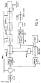
- FIG. 5 represents an embodiment of an encoder-decoder according to the invention.
- the decoding part of a distant image received as it is produced from the diagram of functional blocks of FIG. 4 is produced by the decoding loop shown in FIG. 3.
- the coder-decoder therefore makes it possible to carry out coding of the image signals with a view to reducing the bit rate of the information intended to be transmitted and, on the other hand, to carry out both the decoding local data sent online to reconstruct the image stored in the coding loop, this image must be identical to the image constructed by the remote decoder, and also to decode the data arriving from the remote coder so as to reconstruct the image sent to the other end of the line.
- the local image and the distant image are those that two distant subscribers in communication communicate with each other.
- the coder-decoder is provided with a coding loop comprising a multiprocessor system in which the processors are linked together by bidirectional links and by a bidirectional common bus.
- the coding loop also includes a double RT buffer register to adapt the data flows transmitted and / or received between the device and the transmission network.
- the multiprocessor system comprises a first image memory A containing the blocks of the image to be processed, a second image memory B containing the blocks of the previous image, a third image memory B ′ containing the blocks of decoded remote image, a first signal processor DSP1 for making the difference between corresponding blocks read in the first and second memories, a second processor DSP2 for, on the one hand carrying out a direct quantification Q of the transformed coefficients of blocks of the local image and a Q ⁇ 1 inverse quantization of these blocks and, on the other hand, perform a Q ⁇ 1 inverse quantization of the received remote image blocks. It also includes a transformation device T, T ⁇ 1, able to obtain the transformed coefficients of the difference from the first processor DSP1 and to obtain the inverse transformation of the data from the second processor DSP2.
- the multiprocessor system further comprises a third signal processor DSP3 for calculating the displacement vectors between a new local image and the previous local image, a fourth signal processor DSP4 for, on the one hand performing entropy coding of the quantized coefficients and performing multiplexing the coded data to be transmitted over the network and, on the other hand, demultiplexing the received data and decoding the entropy coding of this data.
- a third signal processor DSP3 for calculating the displacement vectors between a new local image and the previous local image
- a fourth signal processor DSP4 for, on the one hand performing entropy coding of the quantized coefficients and performing multiplexing the coded data to be transmitted over the network and, on the other hand, demultiplexing the received data and decoding the entropy coding of this data.
- the codec also includes a fourth C and a fifth D image memories. These memories respectively play a role identical to the first and second memories. Indeed, they make it possible to duplicate the information contained in memories A and B and thus to avoid access conflicts between the processors DSP1 and DSP3.
- the link between the processor DSP1 and the transformation device T, T ⁇ 1, is bidirectional.
- the link between the processor DSP2 and this device T, T ⁇ 1 is also bidirectional, as are the links between the processor DSP2, DSP4 and between the processor DSP4 and the buffer register RT.
- the processor DSP1, the device T, T ⁇ 1, the processor DSP2, the processor DSP4, are bidirectionally connected to a common bus BC.
- the buffer register RT is connected to a network interface which is not shown but which is conventional in itself.
- the image memory A receives the image data from a two-dimensional filter F1, which receives the digital image signals obtained after conversion by means of an analog / digital converter CV1.
- the image memory B ′ delivers the data corresponding to the remote image intended to be displayed to a two-dimensional filter F2, which transmits this digital data to a digital / analog converter CV2 to allow the display of the corresponding images.
- the H261 standard covers bit rates ranging from 48 kbit / s to 2 Mbit / s and provides for two image formats: CIF and quarter CIF.
- the CIF image format corresponds to 360 points x 288 lines, ensuring an automatic digital connection between the different regions of the world.
- the reduced QCIF format is entirely made suitable for videophone.
- the computing power of processors DSP1 to DSP4 makes it possible to process QCIF images, ie 180 points x 144 lines at this frequency.
- the image memories can be sized for images in CIF format.
- the encoder processes approximately two images / s, which is acceptable for remote monitoring, but more difficult for the videophone, except for viewing documents.
- the architecture of the device is unchanged whatever the image format chosen, only the power of the processors must be increased in the case of the CIF format.
- N 5
- the online speed is around 60 Kbit / s and does not allow all the images to be coded.
- the architecture described above remains valid when all the images are coded.
- the images are broken down into blocks of size 16 x 16 or 8 x 8.
- the calculations are carried out by block.
- the DSP3 processor makes it possible to calculate the displacement vectors between the new image, which is in the image memory C, and the image contained in the memory D. These displacement vectors are then transmitted to the processor DSP1 via the register RTV .
- the transform is a cosine transform in the given application.
- the DSP4 processor makes it possible to perform entropy coding, that is to say to assign a code word of variable length to the coefficient (two-dimensional coding) and to form the digital frame (establishment of header images, groups, blocks, macroblocks, conventionally).
- the DSP1 processor then retrieves the data from the device transforms into a cosine, performs the addition with offset blocks, possibly filtered (coming from memory B), which it has stored in its internal memory and writes the result (a block of the new reconstructed image) in memories B and D.
- the double buffer register RT makes it possible to adapt the data streams which are constant on networks at fixed rates, to those of the coder-decoder which are variable. These flow rates are of course equal on average.
- the link between the double register RT and the processor DSP4 is reversible as well as that between the processor DSP4 and DSP2.
- the loop memory B is duplicated so that this memory contains the reconstructed image of the coder and that the other memory, that of the memory B ′, contains that of the decoder.
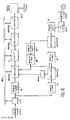
- Figure 6 corresponds to an alternative embodiment of the coder-decoder according to Figure 5.
- This figure has the same elements as those of Figure 5 (these same elements have the same references) and two additional elements corresponding to this variant.
- It is a signal processor DSP5 and an image memory E.
- the signal processor DSP5 makes it possible to carry out a processing called post processing which one will find a description in the French patent applications published under the numbers FR 2589020 and FR 2599577.
- the content of the memory B ′ can therefore be viewed directly or else via the processor DSP5 and the added image memory E.
- two-dimensional filters F1 and F2 are used, necessary in the particular application which has been given by way of example, to effect the changes in image format. These filters do not play any particular role in the architecture described other than that of this change in CIF and QCIF format.
- the coder-decoder according to the invention makes it possible to considerably reduce the size of the devices usually used in this type of application. Indeed, the decoding part of the local image also makes it possible to process the distant images.
- the workload of the decoder part is better used than in conventional decoders.
- the fixed blocks that is to say those for which all the coefficients are zero at the output of the cosine transform device, do not have to be quantized and then dequantized, etc. so that the signal processor DSP2 does nothing for these particular blocks.
- these represent at least 30% of all the images coded at 64Kbit / s.
- This reduction in the computational load of the DSP2 processor is used to process the blocks received (which too are at most 70% on average to be non-fixed). The workload of the DSP2 processor is therefore better used.
- Processors DSP1 to DSP5 can be Motorola 56001 devices.
- the direct and inverse cosine transformation circuit can be a TV3200 circuit from SGS THOMSON.
- the filters F1 and F2 are 2D ASIC filters for example from THOMSON.
- the DSP4 processor can be the Texas TMS320C25 circuit.
- the device according to the invention can be produced with standard, specific or DSP components in accordance with the example given.
Landscapes
- Engineering & Computer Science (AREA)
- Multimedia (AREA)
- Signal Processing (AREA)
- Compression Or Coding Systems Of Tv Signals (AREA)
- Image Processing (AREA)
Claims (8)
- Vorrichtung zur Codierung-Decodierung von Bildsignalen mittels Prädiktion-Transformation, umfassend Codiereinrichtungen von den zu übertragenden Signalen eines örtlichen Bildes und Decodiereinrichtungen von empfangenen Signalen eines entfernten Bildes, wobei diese Signale übertragen werden durch ein Übertragungsnetz einer gegebenen Leistung, wobei die Codiereinrichtungen dieser Vorrichtung gebildet werden durch eine Codierschleife eines in Blöcke zerlegten Bildes, die umfaßt:- einen Codierer, Transformationseinrichtungen (T) und Quantifizierungseinrichtungen (Q) umfassend, um die Differenz zwischen jedem Block eines örtlichen Bildes und dem entsprechenden Block des vorhergehenden örtlichen Bildes zu codieren,- einen Decodierer, inverse Transformationseinrichtungen (T⁻¹) und inverse Quantifizierungseinrichtungen (Q⁻¹) umfassend, die ermöglichen, jeden Block eines Bildes zu decodieren, um diese Blöcke wiederherzustellen, um sie von den Blöcken des nachfolgenden Bildes zu subtrahieren,dadurch gekennzeichnet, daß die
Decodiereinrichtungen des empfangenen entfernten Bildes gebildet werden durch den Decodierer der Codierschleife des örtlichen Bildes, wobei dieser Decodierer somit die Decodierung der Blöcke des örtlichen Bildes gewährleistet und die Decodierung der Blöcke des entfernten Bildes. - Codier-Decodiervorrichtung nach Anspruch 1, dadurch gekennzeichnet, daß die Einrichtungen der Transformation (T) und der inversen Transformation (T⁻¹) realisiert sind durch ein und dieselbe Vorrichtung und die Einrichtungen der Quantifizierung und der inversen Quantifizierung ebenfalls realsiert sind durch ein und dieselbe Vorrichtung, so daß die Decodierung durch den Codierer realisiert wird.
- Codier-Decodiervorrichtung nach Anspruch 1 oder 2, dadurch gekennzeichnet, daß der Codierer und der Decodierer der Codierschleife umfaßt:- ein Multiprozessorsystem, bei dem die Prozessoren miteinander verbunden sind durch bidirektionelle Verbindungen und durch einen gemeinsamen bidirektionellen Bus (BC),- ein Doppel-Pufferregister (RT), um Flüsse von zwischen der Vorrichtung und dem Übertragungsnetz übertragenen und/oder empfangenen Daten anzupassen.
- Codier-Decodiervorrichtung nach Anspruch 1 oder 2, dadurch gekennzeichnet, daß das Multiprozessorsystem umfaßt:- einen ersten (A) Bildspeicher, der die Blöcke des zu verarbeitenden Bilds enhält,- einen zweiten (B) Bildspeicher, der die Blöcke des vorhergehenden Bilds enthält,- einen dritten (B′) Bildspeicher, der die Blöcke des decodierten, entfernten Bilds enthält,- einen ersten Signalprozessor (DSP1), um die Differenz auszuführen zwischen den sich entsprechenden Blöcken, gelesen in dem ersten und dem zweiten Speicher,- einen zweiten Prozessor (DSP2), um einerseits eine direkte Quantifizierung (Q) der transformierten Koeffizienten der örtlichen Bildblöcke durchzuführen und eine inverse Quantifizierung (Q⁻¹) dieser Blöcke, und andererseits eine inverse Quantifizierung (Q⁻¹) der Blöcke des empfangenen entfernten Bildes durchzuführen,- die Transformationvorrichtung (T, T⁻¹), die fähig ist, transformierte Koeffizienten von der vom ersten Prozessor (DSP1) abgeleitenten Differenz zu erhalten, und die inverse Transformation der vom zweiten Prozessor (DSP2) abgeleiteten Daten zu erhalten.
- Codier-Decodiervorrichtung nach Anspruch 3, dadurch gekennzeichnet, daß das Multiprozessorsystem außerdem umfaßt:- einen dritten Signalprozessor (DSP3), um die Verschiebungsvektoren zwischen einem neuen örtlichen Bild und einem vorhergehenden örtlichen Bild zu berechnen,- einen vierten Signalprozessor (DSP4), um einerseits eine entropische Codierung der quantifizierten Koeffizienten durchzuführen und ein Multiplexing der codierten Daten, um sie auf dem Netz zu übertragen, und andererseits die empfangenen Daten zu demultiplexen und die entropische Codierung dieser Daten zu decodieren.
- Codier-Decodiervorrichtung nach Anspruch 3 oder Anspruch 4, dadurch gekennzeichnet, das das Multiprozessorsystem ebenfalls einen vierten (C) und fünften (D) Bildspeicher umfaßt, wobei diese Speicher jeweils eine dem ersten und zweiten Speicher identische Rolle spielen, wobei die Verdopplung es ermöglicht, Zugriffskonflikte zwischen dem ersten und dem dritten Prozessor (DSP1, DSP3) zu vermeiden.
- Codier-Decodiervorrichtung nach einem der Ansprüche 1 bis 6, dadurch gekennzeichnet, daß sie einen fünften Signalprozessor (DSP5) umfaßt, um an den vom dritten Bildspeicher (B′) stammenden Daten eine Nachverarbeitung durchzuführen, und einen sechsten Bildspeicher (E), um diese Daten zu speichern.
- Codier-Decodiervorrichtung nach einem der Ansprüche 1 bis 6, dadurch gekennzeichnet, daß sie außerdem einen AnalogDigital-Wandler (CV1) für das zu übertragende örtliche Bildsignal umfaßt, gefolgt von einem Filter 2D (F1) und einem Digital-Analog-Wandler (CV2) der Daten, die dem empfangenen Signal des entfernten Bilds entsprechen.
Applications Claiming Priority (2)
| Application Number | Priority Date | Filing Date | Title |
|---|---|---|---|
| FR9003817 | 1990-03-26 | ||
| FR9003817A FR2660138B1 (fr) | 1990-03-26 | 1990-03-26 | Dispositif de codage/decodage de signaux d'image. |
Publications (2)
| Publication Number | Publication Date |
|---|---|
| EP0449715A1 EP0449715A1 (de) | 1991-10-02 |
| EP0449715B1 true EP0449715B1 (de) | 1995-01-04 |
Family
ID=9395099
Family Applications (1)
| Application Number | Title | Priority Date | Filing Date |
|---|---|---|---|
| EP91400794A Expired - Lifetime EP0449715B1 (de) | 1990-03-26 | 1991-03-25 | Einrichtung zur Kodierung/Dekodierung von Bildsignalen |
Country Status (5)
| Country | Link |
|---|---|
| US (1) | US5193002A (de) |
| EP (1) | EP0449715B1 (de) |
| JP (1) | JP2941472B2 (de) |
| DE (1) | DE69106415T2 (de) |
| FR (1) | FR2660138B1 (de) |
Families Citing this family (38)
| Publication number | Priority date | Publication date | Assignee | Title |
|---|---|---|---|---|
| GB9405914D0 (en) * | 1994-03-24 | 1994-05-11 | Discovision Ass | Video decompression |
| EP0576749B1 (de) | 1992-06-30 | 1999-06-02 | Discovision Associates | Datenpipelinesystem |
| FR2683694A1 (fr) * | 1991-11-08 | 1993-05-14 | Matra Communication | Dispositif de codage de signal video a activite temporelle. |
| US5355450A (en) * | 1992-04-10 | 1994-10-11 | Avid Technology, Inc. | Media composer with adjustable source material compression |
| WO1993012613A1 (en) * | 1991-12-13 | 1993-06-24 | Avid Technology, Inc. | Quantization table adjustment |
| WO1993012481A2 (en) * | 1991-12-13 | 1993-06-24 | Avid Technology, Inc. | Buffer and frame indexing |
| JPH05236466A (ja) * | 1992-02-25 | 1993-09-10 | Nec Corp | 動き補償フレーム間予測画像符号化装置及び方法 |
| FR2688958B1 (fr) * | 1992-03-17 | 1997-06-27 | Thomson Csf | Procede de codage d'images bi-standard tres bas debit et codeur-decodeur pour la mise en óoeuvre de ce procede. |
| JPH05308622A (ja) * | 1992-04-28 | 1993-11-19 | Mitsubishi Electric Corp | 画像符号化・復号化装置 |
| US6435737B1 (en) | 1992-06-30 | 2002-08-20 | Discovision Associates | Data pipeline system and data encoding method |
| US5784631A (en) | 1992-06-30 | 1998-07-21 | Discovision Associates | Huffman decoder |
| US6330665B1 (en) | 1992-06-30 | 2001-12-11 | Discovision Associates | Video parser |
| US6067417A (en) | 1992-06-30 | 2000-05-23 | Discovision Associates | Picture start token |
| US7095783B1 (en) | 1992-06-30 | 2006-08-22 | Discovision Associates | Multistandard video decoder and decompression system for processing encoded bit streams including start codes and methods relating thereto |
| US6047112A (en) * | 1992-06-30 | 2000-04-04 | Discovision Associates | Technique for initiating processing of a data stream of encoded video information |
| US5768561A (en) | 1992-06-30 | 1998-06-16 | Discovision Associates | Tokens-based adaptive video processing arrangement |
| US5809270A (en) | 1992-06-30 | 1998-09-15 | Discovision Associates | Inverse quantizer |
| US6112017A (en) | 1992-06-30 | 2000-08-29 | Discovision Associates | Pipeline processing machine having a plurality of reconfigurable processing stages interconnected by a two-wire interface bus |
| US6079009A (en) | 1992-06-30 | 2000-06-20 | Discovision Associates | Coding standard token in a system compromising a plurality of pipeline stages |
| JPH0622301A (ja) * | 1992-06-30 | 1994-01-28 | Sony Corp | 画像符号化装置 |
| FR2701623B1 (fr) * | 1993-02-12 | 1995-11-17 | Thomson Csf | Procédé d'enregistrement d'images à débit réduit et dispositif pour sa mise en Óoeuvre. |
| DE4305911A1 (de) * | 1993-02-26 | 1994-09-01 | Philips Patentverwaltung | Videodecoder mit einer Steuereinheit |
| US5805914A (en) * | 1993-06-24 | 1998-09-08 | Discovision Associates | Data pipeline system and data encoding method |
| US5861894A (en) * | 1993-06-24 | 1999-01-19 | Discovision Associates | Buffer manager |
| US5768629A (en) * | 1993-06-24 | 1998-06-16 | Discovision Associates | Token-based adaptive video processing arrangement |
| US5699544A (en) * | 1993-06-24 | 1997-12-16 | Discovision Associates | Method and apparatus for using a fixed width word for addressing variable width data |
| CA2145361C (en) * | 1994-03-24 | 1999-09-07 | Martin William Sotheran | Buffer manager |
| CA2145379C (en) * | 1994-03-24 | 1999-06-08 | William P. Robbins | Method and apparatus for addressing memory |
| CA2145365C (en) * | 1994-03-24 | 1999-04-27 | Anthony M. Jones | Method for accessing banks of dram |
| GB9417138D0 (en) | 1994-08-23 | 1994-10-12 | Discovision Ass | Data rate conversion |
| FR2730116A1 (fr) * | 1995-01-31 | 1996-08-02 | Thomson Broadband Systems | Systeme de deport d'un embrouilleur de signal de television |
| EP0779744A3 (de) * | 1995-12-06 | 1997-08-20 | Thomson Multimedia Sa | Verfahren und Einrichtung zur Kodierung digitaler Videosignale |
| KR100269125B1 (ko) * | 1997-10-25 | 2000-10-16 | 윤덕용 | 양자화효과감소를위한영상데이터후처리방법및장치 |
| DE19916604A1 (de) * | 1999-04-13 | 2000-10-26 | Matthias Zahn | Vorrichtung und Verfahren zur Bearbeitung von zeitlich aufeinanderfolgenden Datenpaketen |
| CN1342370A (zh) * | 1999-12-29 | 2002-03-27 | 皇家菲利浦电子有限公司 | 用于图象编码和解码的设备 |
| US8054880B2 (en) | 2004-12-10 | 2011-11-08 | Tut Systems, Inc. | Parallel rate control for digital video encoder with multi-processor architecture and picture-based look-ahead window |
| US7912302B2 (en) * | 2006-09-21 | 2011-03-22 | Analog Devices, Inc. | Multiprocessor decoder system and method |
| CN107172424B (zh) * | 2011-03-30 | 2020-04-14 | Lg 电子株式会社 | 环路滤波方法及其设备 |
Family Cites Families (6)
| Publication number | Priority date | Publication date | Assignee | Title |
|---|---|---|---|---|
| US4710813A (en) * | 1981-06-04 | 1987-12-01 | Compression Labs, Inc. | Low bandwidth video teleconferencing system and method |
| US4887224A (en) * | 1986-08-28 | 1989-12-12 | Canon Kabushiki Kaisha | Image data processing apparatus capable of high-speed data encoding and/or decoding |
| US4774587A (en) * | 1987-06-02 | 1988-09-27 | Eastman Kodak Company | Still video transceiver processor |
| US5028995A (en) * | 1987-10-28 | 1991-07-02 | Hitachi, Ltd. | Picture signal processor, picture signal coder and picture signal interpolator |
| US4985768A (en) * | 1989-01-20 | 1991-01-15 | Victor Company Of Japan, Ltd. | Inter-frame predictive encoding system with encoded and transmitted prediction error |
| US5062136A (en) * | 1990-09-12 | 1991-10-29 | The United States Of America As Represented By The Secretary Of The Navy | Telecommunications system and method |
-
1990
- 1990-03-26 FR FR9003817A patent/FR2660138B1/fr not_active Expired - Lifetime
-
1991
- 1991-03-25 EP EP91400794A patent/EP0449715B1/de not_active Expired - Lifetime
- 1991-03-25 DE DE69106415T patent/DE69106415T2/de not_active Expired - Lifetime
- 1991-03-25 US US07/674,142 patent/US5193002A/en not_active Expired - Lifetime
- 1991-03-26 JP JP3086171A patent/JP2941472B2/ja not_active Expired - Lifetime
Also Published As
| Publication number | Publication date |
|---|---|
| US5193002A (en) | 1993-03-09 |
| JP2941472B2 (ja) | 1999-08-25 |
| JPH0686269A (ja) | 1994-03-25 |
| EP0449715A1 (de) | 1991-10-02 |
| FR2660138A1 (fr) | 1991-09-27 |
| DE69106415T2 (de) | 1995-07-27 |
| FR2660138B1 (fr) | 1992-06-12 |
| DE69106415D1 (de) | 1995-02-16 |
Similar Documents
| Publication | Publication Date | Title |
|---|---|---|
| EP0449715B1 (de) | Einrichtung zur Kodierung/Dekodierung von Bildsignalen | |
| EP0321318B1 (de) | Kodier- und Dekodierverfahren und Vorrichtung für die Bildübertragung über ein Netz mit einem variablen Datenfluss | |
| EP0558377B1 (de) | Videocodec, insbesondere für ein Bildtelefon | |
| FR2627926A1 (fr) | Procede et dispositif de codage de signaux video numeriques, et dispositif de decodage correspondant | |
| FR2932637A1 (fr) | Procede et dispositif de codage d'une sequence d'images | |
| FR2904494A1 (fr) | Procede et dispositif de compression d'image, systeme de telecommunication comportant un tel dispositif et programme mettant en oeuvre un tel procede | |
| FR2575351A1 (fr) | Procede adaptatif de codage et de decodage d'une suite d'images par transformation, et dispositifs pour la mise en oeuvre de ce procede | |
| WO2016059196A1 (fr) | Decodeur, procede et systeme de decodage de flux multimedia | |
| EP1354482A1 (de) | Bildcodierungsverfahren, bilddecodierungsverfahren, vorrichtungen, und entsprechende anwendungen | |
| EP0603947B1 (de) | Vorrichtung zur Kodierung von digitalen Fernbildsignalen | |
| FR2688958A1 (fr) | Procede de codage d'images bi-standard tres bas debit et codeur-decodeur pour la mise en óoeuvre de ce procede. | |
| FR2755527A1 (fr) | Procede de prediction compensee en mouvement et codeur utilisant un tel procede | |
| FR2759524A1 (fr) | Procede et dispositif de codage par estimation de luminance | |
| EP0404238A1 (de) | Signalverarbeitungseinrichtungen vor und nach Übertragung und/oder Speicherung mit Datenflussverminderung, und Verfahren zur Übertragung und/oder Speicherung von Signalen mit solchen Einrichtungen | |
| FR2966680A1 (fr) | Procedes et dispositifs de codage et de decodage d'au moins une image a partir d'un epitome hierarchique, signal et programme d'ordinateur correspondants | |
| FR2927758A1 (fr) | Procede et dispositif de codage-decodage d'images video successives selon un flux video principal en pleine resolution et selon un flux video secondaire en qualite reduite | |
| FR2503966A1 (fr) | Procede de transmission d'une image, a debit reduit; systeme de transmission pour la mise en oeuvre de ce procede | |
| WO1993018615A1 (fr) | Procede de codage d'images a tres bas debit et dispositif de codage-decodage mettant en ×uvre ce procede | |
| EP3843409A1 (de) | Zuweisungsverfahren für einen low-speed-verbindung | |
| FR2654285A1 (fr) | Systeme de compression d'images numeriques appartenant a une sequence d'images, a quantification adaptative en fonction d'une information psychovisuelle. | |
| WO2009004255A1 (fr) | Selection de fonctions de decodage distribuee au decodeur | |
| EP0395507B1 (de) | Sende- und Empfangssystem zum Übertragen von beweglichen Farbbildern und Ton über unabhängige Kanäle | |
| Padmapriya et al. | A ViT‐Based Adaptive Recurrent Mobilenet With Attention Network for Video Compression and Bit‐Rate Reduction Using Improved Heuristic Approach Under Versatile Video Coding | |
| FR2749119A1 (fr) | Camera video numerique a debit sensiblement constant et systeme de transmission utilisant une telle camera | |
| FR2728129A1 (fr) | Dispositif de multiplexage numerique de programmes video |
Legal Events
| Date | Code | Title | Description |
|---|---|---|---|
| PUAI | Public reference made under article 153(3) epc to a published international application that has entered the european phase |
Free format text: ORIGINAL CODE: 0009012 |
|
| AK | Designated contracting states |
Kind code of ref document: A1 Designated state(s): DE GB |
|
| 17P | Request for examination filed |
Effective date: 19920305 |
|
| 17Q | First examination report despatched |
Effective date: 19940323 |
|
| GRAA | (expected) grant |
Free format text: ORIGINAL CODE: 0009210 |
|
| AK | Designated contracting states |
Kind code of ref document: B1 Designated state(s): DE GB |
|
| RHK2 | Main classification (correction) |
Ipc: H04N 7/24 |
|
| REF | Corresponds to: |
Ref document number: 69106415 Country of ref document: DE Date of ref document: 19950216 |
|
| GBT | Gb: translation of ep patent filed (gb section 77(6)(a)/1977) |
Effective date: 19950314 |
|
| PLBE | No opposition filed within time limit |
Free format text: ORIGINAL CODE: 0009261 |
|
| STAA | Information on the status of an ep patent application or granted ep patent |
Free format text: STATUS: NO OPPOSITION FILED WITHIN TIME LIMIT |
|
| 26N | No opposition filed | ||
| REG | Reference to a national code |
Ref country code: GB Ref legal event code: IF02 |
|
| PGFP | Annual fee paid to national office [announced via postgrant information from national office to epo] |
Ref country code: GB Payment date: 20100226 Year of fee payment: 20 |
|
| PGFP | Annual fee paid to national office [announced via postgrant information from national office to epo] |
Ref country code: DE Payment date: 20100302 Year of fee payment: 20 |
|
| REG | Reference to a national code |
Ref country code: DE Ref legal event code: R071 Ref document number: 69106415 Country of ref document: DE |
|
| REG | Reference to a national code |
Ref country code: GB Ref legal event code: PE20 Expiry date: 20110324 |
|
| PG25 | Lapsed in a contracting state [announced via postgrant information from national office to epo] |
Ref country code: GB Free format text: LAPSE BECAUSE OF EXPIRATION OF PROTECTION Effective date: 20110324 |
|
| PG25 | Lapsed in a contracting state [announced via postgrant information from national office to epo] |
Ref country code: DE Free format text: LAPSE BECAUSE OF EXPIRATION OF PROTECTION Effective date: 20110325 |