EP0449765A1 - Drilling machine with gear speed change - Google Patents
Drilling machine with gear speed change Download PDFInfo
- Publication number
- EP0449765A1 EP0449765A1 EP91810107A EP91810107A EP0449765A1 EP 0449765 A1 EP0449765 A1 EP 0449765A1 EP 91810107 A EP91810107 A EP 91810107A EP 91810107 A EP91810107 A EP 91810107A EP 0449765 A1 EP0449765 A1 EP 0449765A1
- Authority
- EP
- European Patent Office
- Prior art keywords
- spring clip
- handle
- bolt
- housing
- operating positions
- Prior art date
- Legal status (The legal status is an assumption and is not a legal conclusion. Google has not performed a legal analysis and makes no representation as to the accuracy of the status listed.)
- Granted
Links
Images


Classifications
-
- F—MECHANICAL ENGINEERING; LIGHTING; HEATING; WEAPONS; BLASTING
- F16—ENGINEERING ELEMENTS AND UNITS; GENERAL MEASURES FOR PRODUCING AND MAINTAINING EFFECTIVE FUNCTIONING OF MACHINES OR INSTALLATIONS; THERMAL INSULATION IN GENERAL
- F16H—GEARING
- F16H59/00—Control inputs to control units of change-speed- or reversing-gearings for conveying rotary motion
- F16H59/02—Selector apparatus
- F16H59/04—Ratio selector apparatus
- F16H59/041—Ratio selector apparatus consisting of a final output mechanism, e.g. ratio selector being directly linked to a shift fork
-
- B—PERFORMING OPERATIONS; TRANSPORTING
- B23—MACHINE TOOLS; METAL-WORKING NOT OTHERWISE PROVIDED FOR
- B23B—TURNING; BORING
- B23B45/00—Hand-held or like portable drilling machines, e.g. drill guns; Equipment therefor
- B23B45/008—Gear boxes, clutches, bearings, feeding mechanisms or like equipment
-
- Y—GENERAL TAGGING OF NEW TECHNOLOGICAL DEVELOPMENTS; GENERAL TAGGING OF CROSS-SECTIONAL TECHNOLOGIES SPANNING OVER SEVERAL SECTIONS OF THE IPC; TECHNICAL SUBJECTS COVERED BY FORMER USPC CROSS-REFERENCE ART COLLECTIONS [XRACs] AND DIGESTS
- Y10—TECHNICAL SUBJECTS COVERED BY FORMER USPC
- Y10T—TECHNICAL SUBJECTS COVERED BY FORMER US CLASSIFICATION
- Y10T74/00—Machine element or mechanism
- Y10T74/20—Control lever and linkage systems
- Y10T74/20576—Elements
- Y10T74/20636—Detents
- Y10T74/2066—Friction
Definitions
- the invention relates to a drilling rig with a manual gearbox for selectively setting different speeds, with a handle that can be rotated in different operating positions relative to the device housing, with switching cams for the manual gearbox, and a spring clip, the ends of which can be latched into latching openings in the operating positions.
- a drill with a rotatable switch button for setting different speeds is known.
- the switch button is held in the respective operating position by means of a spring clip which is clamped to the device housing and can be latched into latching openings on the rotary knob.
- the switching force to be applied to the switch button is determined by the spring force.
- the spring force depends largely on the type of clamping of the spring clip on the device housing. Depending on the type of clamping, different switching forces occur. The formation of the bracket for tightening the spring clip is thus problematic in terms of influencing the spring force.
- the invention has for its object to provide a drill with a simple and easy to assemble handle for setting different operating positions, wherein an uninfluenced by the mounting of the spring clip switching force of the handle is guaranteed.
- the object is achieved in that the spring clip can be rotated by the handle relative to the device housing and the latching openings are arranged on the housing side.
- the spring clip which can be rotated with respect to the device housing, is not impaired with regard to its spring forces by external influences, such as the type of assembly, type of manufacture and the like, so that a switching force which is not influenced by the mounting of the spring clip is achieved.
- the latching openings are preferably arranged on a housing-side bolt.
- the spring clip is expediently rotatable about the bolt.
- the bolt serving in this way as a pivot bearing for the spring clip can be partially gripped by the spring clip under pretension. A simple mounting of the spring clip can thus be achieved.
- a two-point locking of the spring clip on the bolt can advantageously be achieved by providing essentially diametrically opposite locking openings for the ends of the spring clip for the respective operating positions on the bolt.
- the individual pairs of locking openings are arranged at an angle to each other in accordance with the required switching path.
- the spring clip expediently has driving shoulders which interact with the handle.
- driving cams provided on the handle can engage on the driving shoulders.
- the driving shoulders are formed, for example, by wall parts of pocket-shaped bulges of the spring clip into which the driving cams protrude. In this way, rotary movement can be transmitted in both directions of rotation of the spring clip.
- the drilling device shown in FIG. 1 essentially has a device housing 1 with a handle 2 attached to it.
- a switch 3 for an electric motor housed in the device housing 1 is arranged in the handle 2.
- a mechanical gearbox is provided in the device housing 1, via which a tool holder 4 can optionally be given different speeds.
- a side handle 5 sits adjacent to the tool holder 4.
- a handle 6 that can be actuated from the outside is provided.
- the transmission of the rotary movement to the tool holder 4 is interrupted.
- the middle position "0" represents the transition between the two speed-related operating positions "1" and "2".
- the handle 6 consists of a handle 7 and an arm 8 firmly connected to it, which protrudes into the interior of the device and is rotatably mounted on a bolt 1 a connected to the housing 1.
- the latter has two mutually symmetrically arranged driving cams 8a, 8b, which extend parallel to the axis of rotation in the direction of the outside of the housing.
- a support lug 8c is provided on the arm 8.
- a bolt-shaped switching cam 9 which projects on both sides and extends parallel to the axis of rotation, is mounted in the arm 8.
- the switching cam 9 is used to move a slide 11 across the axis of rotation.
- the slider 11 is shaped as a bent sheet metal part and is guided between the side walls 1b, 1c of the device housing 1 and via the bolt 1a which passes through an elongated hole 11a in the slider 11.
- the slide 11 is held on the bolt 1a by means of a locking ring 12.
- two longitudinal recesses 11b, 11c are provided on the slide 11.
- the displacement movement of the slide 11 is transmitted to a shift rod 13 which is suspended in the latter and which is in a known manner in a clutch connection with the manual transmission.
- the handle 6 can be locked in the operating positions "1" and "2".
- a spring clip 14 is used, which partially engages around the bolt 1a and is supported with pretension with the ends 14a, 14b on the jacket of the bolt 1a.
- latching openings 1d, 1e are provided in pairs, into which the ends 14a, 14b spring in for the latching in the respective operating position.
- the spring clip 14 is rotated on the bolt 1a in accordance with the operating positions by the handle 6 via the driving cams 8a, 8b, the driving cams 8a, 8b engaging on driving shoulders 14c and 14d which project substantially radially with respect to the axis of rotation.
- the support lug 8c protrudes on the outside into a recess 14e of the spring clip 14 and prevents the spring clip 14 from escaping radially from the bolt 1a.
- the two operating positions "1" and “2" of the handle 6 are indicated by dash-dotted lines.
Landscapes
- Engineering & Computer Science (AREA)
- Mechanical Engineering (AREA)
- General Engineering & Computer Science (AREA)
- Drilling And Boring (AREA)
Abstract
Das Bohrgerät mit Schaltgetriebe weist zum wahlweisen Einstellen unterschiedlicher Betriebsstellungen eine verdrehbare Handhabe (6) mit einem Schaltnocken (9) auf. Zur Verrastung der Handhabe (6) in der jeweiligen Betriebsstellung ist ein Federbügel (14) vorgesehen, der von der Handhabe (6) gegenüber dem Gerätegehäuse verdrehbar ist. Die Enden (14a, 14b) des Federbügels (14) rasten in Rastöffnungen (1d, 1e) an einem der Drehlagerung der Handhabe (6) dienenden gehäuseseitigen Bolzen (1a) ein.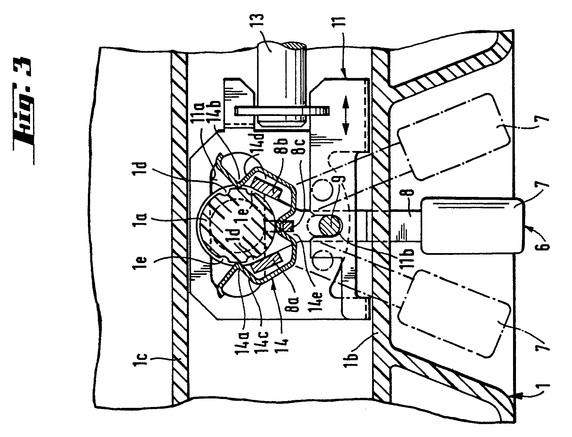
Description
Die Erfindung betrifft ein Bohrgerät mit Schaltgetriebe zum wahlweisen Einstellen unterschiedlicher Drehzahlen, mit einer gegenüber dem Gerätegehäuse in unterschiedliche Betriebsstellungen verdrehbaren, mit Schaltnocken für das Schaltgetriebe versehenen Handhabe und einem Federbügel, dessen Enden in den Betriebsstellungen in Rastöffnungen einrastbar sind.The invention relates to a drilling rig with a manual gearbox for selectively setting different speeds, with a handle that can be rotated in different operating positions relative to the device housing, with switching cams for the manual gearbox, and a spring clip, the ends of which can be latched into latching openings in the operating positions.
Aus der DE-OS 32 40 466 ist ein Bohrgerät mit einem drehbaren Schaltknopf zum Einstellen unterschiedlicher Drehzahlen bekannt. Mittels eines am Gerätegehäuse festgespannten, in Rastöffnungen am Drehknopf einrastbaren Federbügels wird der Schaltknopf in der jeweiligen Betriebsstellung gehalten.From DE-OS 32 40 466 a drill with a rotatable switch button for setting different speeds is known. The switch button is held in the respective operating position by means of a spring clip which is clamped to the device housing and can be latched into latching openings on the rotary knob.
Die am Schaltknopf aufzubringende Schaltkraft wird durch die Federkraft bestimmt. Bei der bekannten Anordnung zeigt sich, dass die Federkraft massgeblich von der Art des Festspannens des Federbügels am Gerätegehäuse abhängt. Je nach Art des Festspannens treten demnach unterschiedliche Schaltkräfte auf. Die Ausbildung der Halterung zum Festpannen des Federbügels ist somit hinsichtlich der Beeinflussung der Federkraft problematisch.The switching force to be applied to the switch button is determined by the spring force. In the known arrangement, it can be seen that the spring force depends largely on the type of clamping of the spring clip on the device housing. Depending on the type of clamping, different switching forces occur. The formation of the bracket for tightening the spring clip is thus problematic in terms of influencing the spring force.
Der Erfindung liegt die Aufgabe zugrunde, ein Bohrgerät mit einer im Aufbau einfachen und montagefreundlichen Handhabe zum Einstellen unterschiedlicher Betriebsstellungen zu schaffen, wobei eine von der Halterung des Federbügels unbeeinflusste Schaltkraft der Handhabe gewährleistet ist.The invention has for its object to provide a drill with a simple and easy to assemble handle for setting different operating positions, wherein an uninfluenced by the mounting of the spring clip switching force of the handle is guaranteed.
Erfindungsgemäss wird die Aufgabe dadurch gelöst, dass der Federbügel gegenüber dem Gerätegehäuse von der Handhabe verdrehbar ist, und die Rastöffnungen gehäuseseitig angeordnet sind.According to the invention, the object is achieved in that the spring clip can be rotated by the handle relative to the device housing and the latching openings are arranged on the housing side.
Bei der erfindungsgemässen Lösung erübrigt sich die Anordnung einer dem Festspannen des Federbügels dienenden Halterung. Der gegenüber dem Gerätegehäuse verdrehbare Federbügel wird hinsichtlich seiner Federkräfte durch äussere Einflüsse, wie Montageart, Fertigungsart und dgl., nicht beeinträchtigt, so dass eine von der Halterung des Federbügels unbeeinflusste Schaltkraft erzielt wird.In the solution according to the invention, there is no need to arrange a holder for clamping the spring clip. The spring clip, which can be rotated with respect to the device housing, is not impaired with regard to its spring forces by external influences, such as the type of assembly, type of manufacture and the like, so that a switching force which is not influenced by the mounting of the spring clip is achieved.
Vorzugsweise sind die Rastöffnungen an einem gehäuseseitigen Bolzen angeordnet. Der Federbügel ist dabei zweckmässig um den Bolzen verdrehbar. Der auf diese Weise als Drehlager für den Federbügel dienende Bolzen kann von dem Federbügel unter Vorspannung teilweise umgriffen sein. Dadurch ist eine einfache Halterung des Federbügels erzielbar.The latching openings are preferably arranged on a housing-side bolt. The spring clip is expediently rotatable about the bolt. The bolt serving in this way as a pivot bearing for the spring clip can be partially gripped by the spring clip under pretension. A simple mounting of the spring clip can thus be achieved.
Eine Zweipunktverrastung des Federbügels auf dem Bolzen ist mit Vorteil erreichbar, indem für die jeweiligen Betriebsstellungen am Bolzen paarweise einander im wesentlichen diametral gegenüberliegende Rastöffnungen für die Enden des Federbügels vorgesehen sind. Die einzelnen Paare der Rastöffnungen sind zueinander entsprechend dem erforderlichen Schaltweg winkelversetzt angeordnet.A two-point locking of the spring clip on the bolt can advantageously be achieved by providing essentially diametrically opposite locking openings for the ends of the spring clip for the respective operating positions on the bolt. The individual pairs of locking openings are arranged at an angle to each other in accordance with the required switching path.
Zur Erzielung einer drehschlüssigen Verbindung mit der Handhabe weist der Federbügel zweckmässig mit der Handhabe zusammenwirkende Mitnahmeschultern auf. An den Mitnahmeschultern können hierzu an der Handhabe vorgesehene Mitnahmenocken angreifen. Die Mitnahmeschultern sind beispielsweise durch Wandungsteile von taschenförmigen Ausbuchtungen des Federbügels gebildet, in welche die Mitnahmenocken einragen. So kann Drehbewegung in beiden Drehrichtungen des Federbügels übertragen werden.In order to achieve a rotational connection with the handle, the spring clip expediently has driving shoulders which interact with the handle. For this purpose, driving cams provided on the handle can engage on the driving shoulders. The driving shoulders are formed, for example, by wall parts of pocket-shaped bulges of the spring clip into which the driving cams protrude. In this way, rotary movement can be transmitted in both directions of rotation of the spring clip.
Die Erfindung wird nachstehend anhand von Zeichnungen, die ein Ausführungsbeispiel wiedergeben, näher erläutet. Es zeigt:
- Fig. 1 ein Bohrgerät in Ansicht;
- Fig. 2 einen vergrösserten Schnitt durch das Bohrgerät, gemäss Schnittverlauf II - II in Fig. 1;
- Fig. 3 einen Schnitt durch die Darstellung nach Fig. 2, gemäss Schnittverlauf III - III in Fig. 2
- Figure 1 is a drill in view.
- FIG. 2 shows an enlarged section through the drilling device, according to section line II-II in FIG. 1;
- 3 shows a section through the representation according to FIG. 2, according to section III - III in FIG. 2
Das in Fig.1 dargestellte Bohrgerät weist im wesentlichen ein Gerätegehäuse 1 mit einem daran befestigten Handgriff 2 auf. Im Handgriff 2 ist ein Schalter 3 für einen im Gerätegehäuse 1 untergebrachten Elektromotor angeordnet. Ferner ist im Gerätegehäuse 1 ein mechanisches Schaltgetriebe vorgesehen, über das einer Werkzeugaufnahme 4 wahlweise unterschiedliche Drehzahlen vermittelt werden können. Am bohrrichtungsseitigen Ende des Gerätegehäuses 1 sitzt angrenzend an die Werkzeugaufnahme 4 ein Seitengriff 5.The drilling device shown in FIG. 1 essentially has a device housing 1 with a
Zum Einstellen in unterschiedliche Drehzahlen bewirkende Betriebsstellungen "1", "2" ist eine von aussen betätigbare Handhabe 6 vorgesehen. In der gezeigten Mittelstellung "0" ist die Uebertragung der Drehbewegung an die Werkzeugaufnahme 4 unterbrochen. Die Mittelstellung "0" stellt die Uebergangstellung zwischen den beiden drehzahlbezogenen Betriebsstellungen "1" und "2" dar.For setting operating positions "1", "2" causing different speeds, a handle 6 that can be actuated from the outside is provided. In the middle position "0" shown, the transmission of the rotary movement to the tool holder 4 is interrupted. The middle position "0" represents the transition between the two speed-related operating positions "1" and "2".
Wie die Fig. 2 und 3 zeigen, besteht die Handhabe 6 aus einem Griffstück 7 und einem mit diesem fest verbundenen Arm 8, der in das Geräteinnere einragt und an einem mit dem Gehäuse 1 einstückig verbundenen Bolzen 1a drehgelagert ist. Ausserhalb des Drehpunktes des Armes 8 weist dieser zwei zueinander symmetrisch angeordnete Mitnahmenocken 8a, 8b auf, welche sich parallel zur Drehachse in Richtung Gehäuseaussenseite erstrecken. Ferner ist am Arm 8 eine Stütznase 8c vorgesehen. In grösserem Radialabstand als die Stütznase 8c ist im Arm 8 ein diesen beidseitig überragender, parallel zur Drehachse sich erstreckender bolzenförmiger Schaltnocken 9 gelagert.As shown in FIGS. 2 and 3, the handle 6 consists of a handle 7 and an
Der Schaltnocken 9 dient dem Verschieben eines Schiebers 11 quer zur Drehachse. Der Schieber 11 ist als Blechbiegeteil geformt und zwischen Seitenwänden 1b, 1c des Gerätegehäuses 1 sowie über den Bolzen 1a, der ein Langloch 11a im Schieber 11 durchgreift, geführt. Mittels eines Sicherungsringes 12 wird der Schieber 11 auf dem Bolzen 1a gehalten. Zum Mitnahmeeingriff des Schaltnockens 9 sind am Schieber 11 zwei Längsausnehmungen 11b, 11c vorgesehen. Die Verschiebebewegung des Schiebers 11 wird auf eine in diesen eingehängte Schaltstange 13 übertragen, welche in an sich bekannter Weise mit dem Schaltgetriebe in Rupplungsverbindung steht.The
Die Handhabe 6 ist in den Betriebsstellungen "1" und "2" verrastbar. Hierzu dient ein Federbügel 14, der den Bolzen 1a teilweise umgreift und unter Vorspannung mit den Enden 14a, 14b sich am Mantel des Bolzens 1a abstützt. Am Mantel des Bolzens 1a sind paarweise Rastöffnungen 1d, 1e vorgesehen, in welche in der jeweiligen Betriebsstellung die Enden 14a, 14b zur Verrastung federnd eintauchen. Der Federbügel 14 wird hierzu entsprechend den Betriebstellungen von der Handhabe 6 über die Mitnahmenocken 8a, 8b auf dem Bolzen 1a verdreht, wobei die Mitnahmenocken 8a, 8b an gegenüber der Drehachse im wesentlichen radial abstehenden Mitnahmeschultern 14c bzw. 14d angreifen. Die Stütznase 8c ragt aussenseitig in eine Vertiefung 14e des Federbügels 14 ein und verhindert ein radiales Entweichen des Federbügels 14 vom Bolzen 1a. In Fig. 3 sind die beiden Betriebsstellungen "1" und "2" der Handhabe 6 strichpunktiert angedeutet.The handle 6 can be locked in the operating positions "1" and "2". For this purpose, a
Claims (5)
Applications Claiming Priority (2)
| Application Number | Priority Date | Filing Date | Title |
|---|---|---|---|
| DE4010037 | 1990-03-29 | ||
| DE4010037A DE4010037A1 (en) | 1990-03-29 | 1990-03-29 | Speed adjusting mechanism for portable drill - has switch lever movement constrained by spring clip exerting force |
Publications (2)
| Publication Number | Publication Date |
|---|---|
| EP0449765A1 true EP0449765A1 (en) | 1991-10-02 |
| EP0449765B1 EP0449765B1 (en) | 1994-01-05 |
Family
ID=6403289
Family Applications (1)
| Application Number | Title | Priority Date | Filing Date |
|---|---|---|---|
| EP91810107A Expired - Lifetime EP0449765B1 (en) | 1990-03-29 | 1991-02-18 | Drilling machine with gear speed change |
Country Status (4)
| Country | Link |
|---|---|
| US (1) | US5111889A (en) |
| EP (1) | EP0449765B1 (en) |
| JP (1) | JP3095082B2 (en) |
| DE (2) | DE4010037A1 (en) |
Cited By (1)
| Publication number | Priority date | Publication date | Assignee | Title |
|---|---|---|---|---|
| EP0448509B1 (en) * | 1990-03-23 | 1993-10-06 | Agathon A.G. Maschinenfabrik | Centreless cylindrical grinding machine |
Families Citing this family (15)
| Publication number | Priority date | Publication date | Assignee | Title |
|---|---|---|---|---|
| JP3424880B2 (en) * | 1995-08-18 | 2003-07-07 | 株式会社マキタ | Hammer drill |
| DE19545260A1 (en) * | 1995-11-24 | 1997-05-28 | Black & Decker Inc | Hammer drill |
| JP3609626B2 (en) * | 1998-09-16 | 2005-01-12 | 株式会社マキタ | Hammer drill |
| USD442452S1 (en) | 1999-08-13 | 2001-05-22 | Black & Decker Inc. | Rotary hammer |
| USD466780S1 (en) | 2000-03-16 | 2002-12-10 | Black & Decker Inc. | Hammer drill |
| GB2394517A (en) * | 2002-10-23 | 2004-04-28 | Black & Decker Inc | Powered hammer having a spindle lock with synchronising element |
| EP1674207B1 (en) | 2004-12-23 | 2008-12-10 | BLACK & DECKER INC. | Power tool |
| EP1674743B1 (en) | 2004-12-23 | 2014-01-22 | Black & Decker Inc. | Drive mechanism for a power tool |
| USD524626S1 (en) * | 2005-02-10 | 2006-07-11 | Black & Decker Inc. | Hammer |
| USD527601S1 (en) * | 2005-02-10 | 2006-09-05 | Black & Decker Inc. | Hammer |
| USD540642S1 (en) * | 2005-02-10 | 2007-04-17 | Black & Decker Inc. | Hammer |
| JP4812471B2 (en) * | 2006-03-09 | 2011-11-09 | 株式会社マキタ | Work tools |
| DE102007010180A1 (en) * | 2007-03-02 | 2008-09-04 | Robert Bosch Gmbh | Hand-held machine tool, especially hammer drill and/or chisel, has first and second joint units arranged to form loss protection for actuating unit with actuating unit in mounted state |
| US9289886B2 (en) | 2010-11-04 | 2016-03-22 | Milwaukee Electric Tool Corporation | Impact tool with adjustable clutch |
| WO2013103610A1 (en) * | 2012-01-04 | 2013-07-11 | Longyear Tm, Inc. | Over center drill head gear shifting system |
Citations (4)
| Publication number | Priority date | Publication date | Assignee | Title |
|---|---|---|---|---|
| US2561930A (en) * | 1948-01-30 | 1951-07-24 | Triplett Electrical Instr Co | Selector switch |
| FR1073433A (en) * | 1952-01-22 | 1954-09-24 | Notched marking device, intended in particular for electric rotary switches | |
| FR1564253A (en) * | 1967-04-27 | 1969-04-18 | ||
| DE3240466A1 (en) * | 1981-11-13 | 1983-05-19 | Black & Decker, Inc., 19711 Newark, Del. | POWERED TOOL |
Family Cites Families (4)
| Publication number | Priority date | Publication date | Assignee | Title |
|---|---|---|---|---|
| DE2122582C3 (en) * | 1971-05-07 | 1980-01-10 | Robert Bosch Gmbh, 7000 Stuttgart | Hand-operated rotary percussion drill |
| DE2136523C3 (en) * | 1971-07-21 | 1983-11-03 | Hilti AG, 9494 Schaan | Electric hammer |
| DE2328462C2 (en) * | 1973-06-05 | 1985-08-29 | Robert Bosch Gmbh, 7000 Stuttgart | Impact drill |
| DE2728961C2 (en) * | 1977-06-27 | 1991-08-08 | Hilti Ag, Schaan | Rotary hammer with lockable tool holder |
-
1990
- 1990-03-29 DE DE4010037A patent/DE4010037A1/en not_active Withdrawn
-
1991
- 1991-02-18 EP EP91810107A patent/EP0449765B1/en not_active Expired - Lifetime
- 1991-02-18 DE DE91810107T patent/DE59100790D1/en not_active Expired - Fee Related
- 1991-03-11 JP JP03069519A patent/JP3095082B2/en not_active Expired - Fee Related
- 1991-03-25 US US07/674,564 patent/US5111889A/en not_active Expired - Fee Related
Patent Citations (4)
| Publication number | Priority date | Publication date | Assignee | Title |
|---|---|---|---|---|
| US2561930A (en) * | 1948-01-30 | 1951-07-24 | Triplett Electrical Instr Co | Selector switch |
| FR1073433A (en) * | 1952-01-22 | 1954-09-24 | Notched marking device, intended in particular for electric rotary switches | |
| FR1564253A (en) * | 1967-04-27 | 1969-04-18 | ||
| DE3240466A1 (en) * | 1981-11-13 | 1983-05-19 | Black & Decker, Inc., 19711 Newark, Del. | POWERED TOOL |
Cited By (1)
| Publication number | Priority date | Publication date | Assignee | Title |
|---|---|---|---|---|
| EP0448509B1 (en) * | 1990-03-23 | 1993-10-06 | Agathon A.G. Maschinenfabrik | Centreless cylindrical grinding machine |
Also Published As
| Publication number | Publication date |
|---|---|
| US5111889A (en) | 1992-05-12 |
| DE4010037A1 (en) | 1991-10-02 |
| JPH04360708A (en) | 1992-12-14 |
| JP3095082B2 (en) | 2000-10-03 |
| EP0449765B1 (en) | 1994-01-05 |
| DE59100790D1 (en) | 1994-02-17 |
Similar Documents
| Publication | Publication Date | Title |
|---|---|---|
| EP0449765B1 (en) | Drilling machine with gear speed change | |
| EP1395468B1 (en) | Wiper arm, especially for a windscreen-wiping device of a motor vehicle | |
| DE2658274C3 (en) | Bearing for a manual shift lever for change gears of vehicles | |
| DE102004057686A1 (en) | switching device | |
| DE4013512A1 (en) | SWITCHING DEVICE FOR SWITCHING A POWERED TOOL | |
| EP0933563B1 (en) | Shift device for gear transmission of motor vehicles | |
| EP0913289A1 (en) | Accelerator pedal unit for vehicles | |
| DE102004036420A1 (en) | Power tools handle | |
| DE3941352C2 (en) | Electromotive actuator | |
| EP0233354A1 (en) | Gear change device for gearboxes of motor vehicles | |
| DE102004007390A1 (en) | Locking unit for a movable locking element | |
| EP0350497A1 (en) | Gear-changing console. | |
| DE4110169C2 (en) | ||
| EP0040261A1 (en) | Electrical tool with a two-speed gear | |
| DE102005001818A1 (en) | Switching device for an automatic transmission of a motor vehicle | |
| DE19703931A1 (en) | Switches for controlling bicycle transmissions | |
| DE3808272C2 (en) | ||
| DE60115367T2 (en) | Door handle assembly for a sliding door of a motor vehicle | |
| DE4003899C1 (en) | ||
| DE2830511A1 (en) | Two-speed impact drill - has selector ring on shaft hub with four recesses accommodating selector pin | |
| DE60021640T2 (en) | With handlebar mounted steering column switch for driving direction display friction or button switch or the like | |
| EP0775854A2 (en) | Gear shift mechanism for vehicle transmission, incorporating torsion bar | |
| DE4445661C1 (en) | Pedal control system for industrial trucks | |
| DE2215286C3 (en) | Shift linkages for motor vehicles | |
| DE2831572C3 (en) | The exterior mirror can be adjusted from inside the vehicle |
Legal Events
| Date | Code | Title | Description |
|---|---|---|---|
| PUAI | Public reference made under article 153(3) epc to a published international application that has entered the european phase |
Free format text: ORIGINAL CODE: 0009012 |
|
| AK | Designated contracting states |
Kind code of ref document: A1 Designated state(s): CH DE FR GB LI |
|
| 17P | Request for examination filed |
Effective date: 19911104 |
|
| 17Q | First examination report despatched |
Effective date: 19930303 |
|
| GRAA | (expected) grant |
Free format text: ORIGINAL CODE: 0009210 |
|
| AK | Designated contracting states |
Kind code of ref document: B1 Designated state(s): CH DE FR GB LI |
|
| REF | Corresponds to: |
Ref document number: 59100790 Country of ref document: DE Date of ref document: 19940217 |
|
| ET | Fr: translation filed | ||
| GBT | Gb: translation of ep patent filed (gb section 77(6)(a)/1977) |
Effective date: 19940211 |
|
| PLBE | No opposition filed within time limit |
Free format text: ORIGINAL CODE: 0009261 |
|
| 26N | No opposition filed | ||
| PGFP | Annual fee paid to national office [announced via postgrant information from national office to epo] |
Ref country code: FR Payment date: 19981230 Year of fee payment: 9 |
|
| PGFP | Annual fee paid to national office [announced via postgrant information from national office to epo] |
Ref country code: GB Payment date: 19990208 Year of fee payment: 9 |
|
| PG25 | Lapsed in a contracting state [announced via postgrant information from national office to epo] |
Ref country code: GB Free format text: LAPSE BECAUSE OF NON-PAYMENT OF DUE FEES Effective date: 20000218 |
|
| GBPC | Gb: european patent ceased through non-payment of renewal fee |
Effective date: 20000218 |
|
| PG25 | Lapsed in a contracting state [announced via postgrant information from national office to epo] |
Ref country code: FR Free format text: LAPSE BECAUSE OF NON-PAYMENT OF DUE FEES Effective date: 20001031 |
|
| REG | Reference to a national code |
Ref country code: FR Ref legal event code: ST |
|
| PGFP | Annual fee paid to national office [announced via postgrant information from national office to epo] |
Ref country code: DE Payment date: 20090123 Year of fee payment: 19 |
|
| PGFP | Annual fee paid to national office [announced via postgrant information from national office to epo] |
Ref country code: CH Payment date: 20090302 Year of fee payment: 19 |
|
| REG | Reference to a national code |
Ref country code: CH Ref legal event code: PL |
|
| PG25 | Lapsed in a contracting state [announced via postgrant information from national office to epo] |
Ref country code: CH Free format text: LAPSE BECAUSE OF NON-PAYMENT OF DUE FEES Effective date: 20100228 Ref country code: LI Free format text: LAPSE BECAUSE OF NON-PAYMENT OF DUE FEES Effective date: 20100228 |
|
| PG25 | Lapsed in a contracting state [announced via postgrant information from national office to epo] |
Ref country code: DE Free format text: LAPSE BECAUSE OF NON-PAYMENT OF DUE FEES Effective date: 20100901 |