EP0449836B1 - Detecteur de vitesse angulaire - Google Patents
Detecteur de vitesse angulaire Download PDFInfo
- Publication number
- EP0449836B1 EP0449836B1 EP89910065A EP89910065A EP0449836B1 EP 0449836 B1 EP0449836 B1 EP 0449836B1 EP 89910065 A EP89910065 A EP 89910065A EP 89910065 A EP89910065 A EP 89910065A EP 0449836 B1 EP0449836 B1 EP 0449836B1
- Authority
- EP
- European Patent Office
- Prior art keywords
- sensor
- component
- angular velocity
- sensor according
- charges
- Prior art date
- Legal status (The legal status is an assumption and is not a legal conclusion. Google has not performed a legal analysis and makes no representation as to the accuracy of the status listed.)
- Expired - Lifetime
Links
- 230000010355 oscillation Effects 0.000 claims description 11
- 230000033001 locomotion Effects 0.000 claims description 8
- 230000001419 dependent effect Effects 0.000 claims description 3
- 238000001914 filtration Methods 0.000 claims description 3
- 239000000758 substrate Substances 0.000 claims 1
- 230000005284 excitation Effects 0.000 abstract description 17
- 238000010276 construction Methods 0.000 abstract description 2
- 238000005259 measurement Methods 0.000 description 14
- 230000002452 interceptive effect Effects 0.000 description 4
- 230000035945 sensitivity Effects 0.000 description 4
- 230000000694 effects Effects 0.000 description 3
- 230000000737 periodic effect Effects 0.000 description 3
- 239000000853 adhesive Substances 0.000 description 2
- 230000001070 adhesive effect Effects 0.000 description 2
- 238000005452 bending Methods 0.000 description 2
- 239000000919 ceramic Substances 0.000 description 2
- 238000013461 design Methods 0.000 description 2
- 230000005684 electric field Effects 0.000 description 2
- 238000007667 floating Methods 0.000 description 2
- 238000002955 isolation Methods 0.000 description 2
- 239000002184 metal Substances 0.000 description 2
- 238000012216 screening Methods 0.000 description 2
- 239000000725 suspension Substances 0.000 description 2
- 230000002123 temporal effect Effects 0.000 description 2
- 244000090125 Solidago odora Species 0.000 description 1
- 230000001133 acceleration Effects 0.000 description 1
- 230000005540 biological transmission Effects 0.000 description 1
- 230000015572 biosynthetic process Effects 0.000 description 1
- 230000008878 coupling Effects 0.000 description 1
- 238000010168 coupling process Methods 0.000 description 1
- 238000005859 coupling reaction Methods 0.000 description 1
- 238000001514 detection method Methods 0.000 description 1
- 238000011161 development Methods 0.000 description 1
- 230000018109 developmental process Effects 0.000 description 1
- 238000006073 displacement reaction Methods 0.000 description 1
- 230000005484 gravity Effects 0.000 description 1
- 239000000463 material Substances 0.000 description 1
- 238000001465 metallisation Methods 0.000 description 1
- 238000000034 method Methods 0.000 description 1
- 230000001105 regulatory effect Effects 0.000 description 1
- 230000009291 secondary effect Effects 0.000 description 1
- 238000010008 shearing Methods 0.000 description 1
- 230000001629 suppression Effects 0.000 description 1
- 238000012549 training Methods 0.000 description 1
Images


Classifications
-
- G—PHYSICS
- G01—MEASURING; TESTING
- G01C—MEASURING DISTANCES, LEVELS OR BEARINGS; SURVEYING; NAVIGATION; GYROSCOPIC INSTRUMENTS; PHOTOGRAMMETRY OR VIDEOGRAMMETRY
- G01C19/00—Gyroscopes; Turn-sensitive devices using vibrating masses; Turn-sensitive devices without moving masses; Measuring angular rate using gyroscopic effects
- G01C19/56—Turn-sensitive devices using vibrating masses, e.g. vibratory angular rate sensors based on Coriolis forces
Definitions
- the invention relates to a sensor for determining the angular velocity.
- Known vibration gyrometers generally work with low-frequency bending oscillators, e.g. rod oscillators, cylinder oscillators or tuning fork oscillators.
- rod oscillators e.g. rod oscillators
- cylinder oscillators e.g. rod oscillators
- tuning fork oscillators e.g. rod oscillators, cylinder oscillators or tuning fork oscillators.
- relatively small piezoceramic elements are attached to larger, non-piezoelectric oscillating bodies. These effect the vibration excitation, serve as a sensor for the amplitude control and convert the effects of the Coriolis force on the vibrating body into the measurement signal.
- the oscillation frequencies used are relatively low in all of the gyrometers mentioned and are in the frequency range from vibrations or only a short distance from them, so that the measurement signals obtained are relatively strongly falsified by these interference signals.
- US-A-3 258 617 generally refers to piezoelectric sensors which have a prismatic shape and consist of a monolithic block or are constructed in layers from several parts. Electrodes are arranged on the surfaces of the block or the parts, with the aid of which the sensor is excited to vibrations, in particular shear vibrations, in a first direction and with the aid of vibrations in a third direction when rotating about an axis parallel to a second direction Direction generated energy is tapped.
- references to the concrete subject matter of the present invention are missing. This results in significant differences in the design (e.g. excitation in the direction of the polar axis) and in the underlying physical principle, in particular through the use of piezoceramic thickness shear transducers.
- the sensor according to the invention for determining the angular velocity with the features of claim 1 has the advantage that no additional oscillators are coupled due to the use of a piezoceramic oscillating body for the measurement signal formation. As a result, it has a very simple but mechanically stable structure. The lack of additional elements on the vibrating body improves the behavior when the temperature changes. The sensor also has a relatively low sensitivity to vibrations. The large frequency difference between the signal frequency and the interference frequencies of vibrations achieved with training as a Dickenscherschwinger contributes to this, which enables effective screening by means of a high-pass filter in the signal path.
- FIGS. 3 to 6 each show an exemplary embodiment
- FIG. 7 shows the electrical connection of the sensor to an excitation voltage.
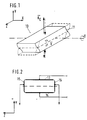
- the measuring principle of the sensor 10 is shown schematically, which in its simplest form consists of a piezoceramic plate 11.
- the sensor 10 in the z direction which by definition represents the direction of the polar axis, is significantly larger than in the other two (x, y) directions.
- the vibration excitation is effected via the electrodes 13, 14 shown in FIG. 2 on the y-surfaces, via which the sensor 10 becomes a frequency-determining element of an oscillator circuit.
- the position of a plane is expressed in a known manner by its normal direction.
- the proportionality factors d15 and d31, ... in the relationships between electrical and mechanical quantities are referred to as piezoelectric coefficients.
- the measurement of angular velocity is based on the Coriolis force that one in the rotating system with speed experiences moving mass m,
- the amount of Coriolis force is the amount of angular velocity proportional to their through the vector product certain direction changes with the direction of rotation of the angular velocity the sign.
- the distance to the axis of rotation is irrelevant.
- the speed is given by the oscillating movement caused by the alternating electric field E y , so that the speed vector as shown in Figure 1, runs parallel to the z-axis.
- the size of the speed vector is zero in the node plane of the plate 11 and its direction changes its sign there.
- the phase of the speed vector periodic Coriolis forces is shifted by ⁇ / 2 compared to the phase of the vibration amplitude.
- the speed amplitude which is determined by the product of the oscillation amplitude and oscillation frequency, can assume sufficient values even in the case of shear vibrations with very small amplitudes in the order of magnitude of micrometers, since the frequency can be made correspondingly large.
- a high vibration frequency e.g. 160 kHz
- the oscillation frequency also being the signal frequency
- the frequency distance from interference signals that result from vibrations is much larger than in known methods.
- the sensitivity to vibrations is lower.
- the orientation of the z-axis to the angular velocity vector to be measured is to be chosen so that the Coriolis forces periodically generated mechanical stresses on the z-surfaces due to the piezoelectric properties periodically generate charges. These charges then represent a measure of the angular velocity.
- the angular velocity vector be oriented parallel to the x-axis.
- D z is the dielectric displacement with the dimension of a surface charge density
- the components of the angular velocity vector generate no Coriolis forces at all because the angular velocity vector parallel to the movement of the vibrating masses. If, for example, the angular velocity about its vertical axis is to be measured when a motor vehicle is cornering, the x-axis of the sensor 10 must run parallel to this axis.
- piezoceramic material is necessary to obtain sufficiently high d31 values.
- the sensitivity can be increased by increasing the plate volume. However, this is subject to narrow limits due to the application conditions.
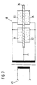
- FIG. 3 shows a design embodiment of the sensor 10.
- the sensor 10 is here suspended in a frame 17 with the aid of contact springs 18.
- the contact springs 18 are used both for the elastic suspension of the sensor 10 in the frame 17 and for the transmission of the electrical measurement signal or the electrical excitation signal to the corresponding electrodes of the sensor 10. Soll If the angular velocity of a rotation about a vertical axis is measured, the frame 17 of the sensor 10 is to be installed horizontally in the rotated overall system.
- Suitable as contact springs 18 are any spring bodies which do not significantly impede the shear vibrations of the sensor 10 and which, through their own conductivity, metallization or in combination with thin wires, simultaneously take over the electrical contact.
- a higher temporal resolution of the measurement signal is achieved with the exemplary embodiment shown in FIG. 4, in which the sensor 10 is held with the aid of two pressure plates 21, 22.
- two longitudinal grooves 24 are formed in the node line of the sensor 10, extending in the x-areas in the z direction, into which the cutting edges of the pressure plates 21, 22 are inserted.
- the resulting shear stresses do not generate any charges on the signal electrodes of the z-surfaces, but charges are generated by all normal stress components X x , Y y , Z z .
- the size of the charges generated in this way can be much larger for the individual plate than the measurement signal at the required detection limit.
- the desired interfering charge compensation then occurs.
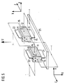
- the signals also add up when the oscillations of the two plates 11, 12 are excited in phase opposition, as shown in the exemplary embodiment according to FIG.
- compressive stresses arise in one sensor plate, while tensile stresses are caused in the other or vice versa.
- FIG. 6 An increase in the output signal and compensation of interference is also possible with the aid of an arrangement according to FIG. 6, which largely corresponds to that according to FIG.
- four piezoelectric plates 31 to 34 are used, which are firmly connected to a base 35.
- the plates 31 to 34 therefore represent ⁇ / 4 oscillators. This creates a very compact and stable arrangement.
- the plates 31 to 34 can, for example, be soldered onto a metal plate or glued to a ceramic base with the aid of a conductive adhesive.
- the metal plate or the Conductive adhesives serve as one of the electrodes 13 and 14 for excitation.
- the z-axis of the plates 31 to 34, ie their polar axes lie in the plane of the base 35.
- the charges generated on the z-electrodes on one side, for example 41 to 44, in FIG. 6 by rotating the sensor about the x-axis have the same sign, so that the four z-electrodes on each side, as well as for the z-electrodes 41 to 44 shown, can be interconnected. As with the sensor 10 according to FIG. 5, the low-frequency interference is then largely compensated for, while the useful signals add up.
- interference voltages with excitation frequency occur even without rotation of the sensor at the signal output, which, although they are not in phase with the signal, must be compensated for as well as possible. They are partly due to the inevitable capacitances between the excitation electrodes and the leads and the signal electrodes. Interference signals are superimposed, which result from piezoelectric secondary effects of the stray fields between the excitation and signal electrodes.
- a partial voltage of suitable size and phase position is formed from the excitation voltage, which at the signal output the sensor plates is overlaid.
- a harmonic signal occurs in sensors with free-floating plates (FIGS.
- the size of the measurement signal depends on the vibration amplitude of the sensors 10, this must be kept constant. This is most reliably possible over a longer period of time by measuring the vibration amplitude.
- the harmonic signal mentioned above is clearly dependent on the vibration amplitude and is therefore suitable for control.
- the excitation voltage is regulated so that a predetermined value of the harmonic signal is kept constant.
- a harmonic signal must be branched off in the signal path before filtering.
- the use of the harmonic signal has the advantage that no additional sensors or electrodes are required for the measurement of the oscillation amplitude, and that a falsification of the control signal by scattering the much larger excitation voltage is practically excluded due to the possibility of filtering.
- additional small electrodes 45, 46 are to be applied to the y-surfaces in addition to the excitation electrodes 36, 37 for the vibration amplitude measurement.
Landscapes
- Physics & Mathematics (AREA)
- Engineering & Computer Science (AREA)
- General Physics & Mathematics (AREA)
- Radar, Positioning & Navigation (AREA)
- Remote Sensing (AREA)
- Gyroscopes (AREA)
Abstract
Claims (7)
- Détecteur (10) pour déterminer la vitesse angulaireen particulier de véhicules à moteurs, qui fonctionne avec au moins un élément piézocéramique (11) à la manière d'un gyromètre d'oscillations, détecteur dans lequel l'élément est constitué comme un oscillateur de cisaillement d'épaisseur et a la forme d'une plaquette, l'axe polaire étant dirigé parallèlement au plan de la plaquette et perpendiculairement aux faces latérales de l'élément (11) et les électrodes d'excitation (13, 14) se trouvant sur les faces de la plaquette de l'élément (11) et des électrodes de mesure (15, 16) étant disposées sur les faces de l'élément (11) perpendiculaires à l'axe polaire, électrodes qui servent à la mesure de la charge proportionnelle à la vitesse angulaire
 de l'élément piézo-céramique (11), l'oscillation de cisaillement étant excitée dans le sens de l'axe polaire et lors de la rotation autour d'un axe de rotation, qui est perpendiculaire à l'axe polaire de l'élément piézo-céramique (11), et parallèlement au plan de l'élément (11) des forces de Coriolis Kc agissant sur le détecteur (10) étant produites, forces qui dégagent sur les faces perpendiculaires à l'axe polaire du ou des éléments (11) des charges, qui sont une mesure de la vitesse angulaire
 de la rotation.
- Détecteur selon la revendication 1, caractérisé en ce que deux supports (21, 22) sont disposés sur le détecteur (10) dans la zone de la ligne nodale (24) du ou des éléments (11).
- Détecteur selon la revendication 2, caractérisé en ce que dans la zone de la ligne nodale du détecteur (10) est constituée une rainure longitudinale (24) sur le détecteur (10), dans laquelle viennent en prise les supports (21, 22).
- Détecteur selon les revendications 1 et/ou 2, caractérisé en ce que le détecteur (10) est disposé dans un cadre (17) à l'aide de ressorts de contact (18) élastiques, conduisant l'électricité,
- Détecteur selon l'une des revendications 1 à 4, caractérisé en ce que le détecteur (10) se compose de deux éléments (11, 12), dont les axes polaires sont orientés parallèlement et qui sont excités en opposition de phase aux oscillations et en ce que deux électrodes de mesure (15, 16) sont branchées ensemble de telle façon que les signaux de mesure s'additionnent, tandis que les charges parasites dûes aux vibrations se compensent.
- Détecteur selon l'une des revendications 1 à 5, caractérisé en ce qu'au moins deux détecteurs sont disposés sur une embase (35) avec chacun deux paires de plaquettes (31, 32 ou 33, 34), dont les axes polaires sont dirigés de la même façon à l'intérieur des paires et dont les mouvements de cisaillement sont amorcés dans les paires de plaquettes en opposition de phase et en croix en phase.
- Détecteur selon l'une des revendications 1 à 5, caractérisé en ce qu'on dévie un signal d'harmoniques se produisant sur les électrodes de mesure (15, 16) du détecteur (10) fonction de la grandeur de l'amplitude d'oscillation avant le filtrage sur le trajet de signal et on l'utilise pour la régulation de l'amplitude d'oscillation.
Applications Claiming Priority (2)
| Application Number | Priority Date | Filing Date | Title |
|---|---|---|---|
| DE3843143 | 1988-12-22 | ||
| DE3843143A DE3843143A1 (de) | 1988-12-22 | 1988-12-22 | Sensor zur bestimmung der winkelgeschwindigkeit |
Publications (2)
| Publication Number | Publication Date |
|---|---|
| EP0449836A1 EP0449836A1 (fr) | 1991-10-09 |
| EP0449836B1 true EP0449836B1 (fr) | 1993-02-10 |
Family
ID=6369782
Family Applications (1)
| Application Number | Title | Priority Date | Filing Date |
|---|---|---|---|
| EP89910065A Expired - Lifetime EP0449836B1 (fr) | 1988-12-22 | 1989-09-16 | Detecteur de vitesse angulaire |
Country Status (7)
| Country | Link |
|---|---|
| US (1) | US5247252A (fr) |
| EP (1) | EP0449836B1 (fr) |
| JP (1) | JPH04502202A (fr) |
| KR (1) | KR910700466A (fr) |
| BR (1) | BR8907844A (fr) |
| DE (2) | DE3843143A1 (fr) |
| WO (1) | WO1990007124A1 (fr) |
Families Citing this family (15)
| Publication number | Priority date | Publication date | Assignee | Title |
|---|---|---|---|---|
| DE4135369A1 (de) * | 1991-10-26 | 1993-05-13 | Bosch Gmbh Robert | Testbarer piezoelektrischer beschleunigungssensor |
| US5767405A (en) | 1992-04-07 | 1998-06-16 | The Charles Stark Draper Laboratory, Inc. | Comb-drive micromechanical tuning fork gyroscope with piezoelectric readout |
| JPH07113644A (ja) * | 1993-10-19 | 1995-05-02 | Shimada Phys & Chem Ind Co Ltd | 振動ジャイロ及びその駆動方法 |
| DE4431232C2 (de) * | 1994-09-02 | 1999-07-08 | Hahn Schickard Ges | Integrierbares Feder-Masse-System |
| JP3189620B2 (ja) * | 1995-04-12 | 2001-07-16 | 株式会社村田製作所 | 圧電振動子 |
| DE10026169C2 (de) * | 1999-05-26 | 2003-06-05 | Deutsch Zentr Luft & Raumfahrt | Verwendung eines elastischen Konstruktionselements als Torsionsfeder |
| US20040215387A1 (en) | 2002-02-14 | 2004-10-28 | Matsushita Electric Industrial Co., Ltd. | Method for transmitting location information on a digital map, apparatus for implementing the method, and traffic information provision/reception system |
| JP3481168B2 (ja) | 1999-08-27 | 2003-12-22 | 松下電器産業株式会社 | デジタル地図の位置情報伝達方法 |
| DE10051775A1 (de) * | 2000-10-19 | 2002-05-16 | Hilti Ag | Sicherheitsschaltung für drehendes Elektrohandwerkzeuggerät |
| JP5041638B2 (ja) | 2000-12-08 | 2012-10-03 | パナソニック株式会社 | デジタル地図の位置情報伝達方法とそれに使用する装置 |
| JP4663136B2 (ja) | 2001-01-29 | 2011-03-30 | パナソニック株式会社 | デジタル地図の位置情報伝達方法と装置 |
| JP4230132B2 (ja) | 2001-05-01 | 2009-02-25 | パナソニック株式会社 | デジタル地図の形状ベクトルの符号化方法と位置情報伝達方法とそれを実施する装置 |
| US7464590B1 (en) * | 2004-03-12 | 2008-12-16 | Thomson Licensing | Digitally programmable bandwidth for vibratory rate gyroscope |
| JP4536016B2 (ja) * | 2006-02-03 | 2010-09-01 | 日本航空電子工業株式会社 | 振動ジャイロ |
| CN105807085A (zh) * | 2016-03-15 | 2016-07-27 | 西安交通大学 | 一种基于压电特性和静电感应的轴承转动测量装置 |
Family Cites Families (6)
| Publication number | Priority date | Publication date | Assignee | Title |
|---|---|---|---|---|
| US3258617A (en) * | 1963-02-07 | 1966-06-28 | Avco Corp | Piezoelectric device |
| US3520195A (en) * | 1965-10-11 | 1970-07-14 | Gen Electric | Solid state angular velocity sensing device |
| US3842681A (en) * | 1973-07-19 | 1974-10-22 | Sperry Rand Corp | Angular rate sensor |
| AU554302B2 (en) * | 1983-09-02 | 1986-08-14 | Sundstrand Data Control, Inc. | Angular rate sensor utilizing parallel vibrating accelerometers |
| CA1217648A (fr) * | 1984-01-23 | 1987-02-10 | Robert E. Stewart | Multicapteur mono-coordonnee |
| US4601205A (en) * | 1984-11-19 | 1986-07-22 | The Singer Company | Linear acceleration compensation for multisensor |
-
1988
- 1988-12-22 DE DE3843143A patent/DE3843143A1/de not_active Ceased
-
1989
- 1989-09-16 US US07/646,605 patent/US5247252A/en not_active Expired - Fee Related
- 1989-09-16 DE DE8989910065T patent/DE58903552D1/de not_active Expired - Fee Related
- 1989-09-16 KR KR1019900701813A patent/KR910700466A/ko not_active Ceased
- 1989-09-16 WO PCT/DE1989/000592 patent/WO1990007124A1/fr not_active Ceased
- 1989-09-16 BR BR898907844A patent/BR8907844A/pt not_active IP Right Cessation
- 1989-09-16 EP EP89910065A patent/EP0449836B1/fr not_active Expired - Lifetime
- 1989-09-16 JP JP1509295A patent/JPH04502202A/ja active Pending
Also Published As
| Publication number | Publication date |
|---|---|
| KR910700466A (ko) | 1991-03-15 |
| US5247252A (en) | 1993-09-21 |
| DE3843143A1 (de) | 1990-06-28 |
| WO1990007124A1 (fr) | 1990-06-28 |
| EP0449836A1 (fr) | 1991-10-09 |
| JPH04502202A (ja) | 1992-04-16 |
| DE58903552D1 (de) | 1993-03-25 |
| BR8907844A (pt) | 1991-10-08 |
Similar Documents
| Publication | Publication Date | Title |
|---|---|---|
| DE69837905T2 (de) | Vibratoren und Vibrationskreisel | |
| EP0449836B1 (fr) | Detecteur de vitesse angulaire | |
| EP0906557B2 (fr) | Detecteur de rotation a oscillations primaires et secondaires orthogonales decouplees | |
| DE19530007C2 (de) | Drehratensensor | |
| DE10335783B4 (de) | Horizontales Vibrationsmikrogyroskop vom Stimmgabeltyp | |
| DE19928759B4 (de) | Winkelgeschwindigkeitssensor | |
| DE69008165T2 (de) | Fühlelement für ein gyroskop. | |
| DE69712375T2 (de) | Winkelgeschwindigkeitsdetektor | |
| DE69822756T2 (de) | Mikromechanischer Schwingkreisel | |
| DE69636910T2 (de) | Vibrationskreisel | |
| DE19519488A1 (de) | Drehratensensor mit zwei Beschleunigungssensoren | |
| DE102010040516A1 (de) | Doppelaxialer, schockrobuster Drehratensensor mit ineinanderliegenden, linear schwingenden seismischen Elementen | |
| DE19643182A1 (de) | Schwingungskonstruktion | |
| DE19801981C2 (de) | Winkelgeschwindigkeitssensor vom Vibrationstyp | |
| EP1472506B1 (fr) | Capteur de vitesse de rotation micromecanique | |
| DE10006933A1 (de) | Mikrokreisel | |
| DE69930652T2 (de) | Monolithischer miniatur-beschleunigungssensor | |
| DE69310315T2 (de) | Vibratordrehungsmessaufnehmer | |
| DE69614340T2 (de) | Gyrometer mit mechanischem Resonator | |
| EP1309834B1 (fr) | Capteur de vitesse de rotation et systeme de capteur de vitesse de rotation | |
| DE3280443T2 (de) | Verbesserte vorrichtung zur isolierung von erschütterungen. | |
| DE19828424C1 (de) | Mikromechanischer Drehratensensor | |
| DE10006931B4 (de) | Mikrogyroskop mit drei entgegengesetzt zueinander schwingenden Massen | |
| DE10147997A1 (de) | Beschleunigungssensor | |
| DE29617410U1 (de) | Drehratensensor mit entkoppelten orthogonalen Primär- und Sekundärschwingungen |
Legal Events
| Date | Code | Title | Description |
|---|---|---|---|
| PUAI | Public reference made under article 153(3) epc to a published international application that has entered the european phase |
Free format text: ORIGINAL CODE: 0009012 |
|
| 17P | Request for examination filed |
Effective date: 19901127 |
|
| AK | Designated contracting states |
Kind code of ref document: A1 Designated state(s): CH DE FR GB IT LI SE |
|
| 17Q | First examination report despatched |
Effective date: 19911216 |
|
| RAP3 | Party data changed (applicant data changed or rights of an application transferred) |
Owner name: ROBERT BOSCH GMBH |
|
| GRAA | (expected) grant |
Free format text: ORIGINAL CODE: 0009210 |
|
| AK | Designated contracting states |
Kind code of ref document: B1 Designated state(s): CH DE FR GB IT LI SE |
|
| ET | Fr: translation filed | ||
| GBT | Gb: translation of ep patent filed (gb section 77(6)(a)/1977) |
Effective date: 19930222 |
|
| REF | Corresponds to: |
Ref document number: 58903552 Country of ref document: DE Date of ref document: 19930325 |
|
| ITF | It: translation for a ep patent filed | ||
| PGFP | Annual fee paid to national office [announced via postgrant information from national office to epo] |
Ref country code: DE Payment date: 19931125 Year of fee payment: 5 |
|
| PGFP | Annual fee paid to national office [announced via postgrant information from national office to epo] |
Ref country code: CH Payment date: 19931208 Year of fee payment: 5 |
|
| PLBE | No opposition filed within time limit |
Free format text: ORIGINAL CODE: 0009261 |
|
| STAA | Information on the status of an ep patent application or granted ep patent |
Free format text: STATUS: NO OPPOSITION FILED WITHIN TIME LIMIT |
|
| 26N | No opposition filed | ||
| PGFP | Annual fee paid to national office [announced via postgrant information from national office to epo] |
Ref country code: GB Payment date: 19940906 Year of fee payment: 6 |
|
| PGFP | Annual fee paid to national office [announced via postgrant information from national office to epo] |
Ref country code: SE Payment date: 19940922 Year of fee payment: 6 |
|
| PG25 | Lapsed in a contracting state [announced via postgrant information from national office to epo] |
Ref country code: LI Effective date: 19940930 Ref country code: CH Effective date: 19940930 |
|
| PGFP | Annual fee paid to national office [announced via postgrant information from national office to epo] |
Ref country code: FR Payment date: 19940930 Year of fee payment: 6 |
|
| EAL | Se: european patent in force in sweden |
Ref document number: 89910065.5 |
|
| REG | Reference to a national code |
Ref country code: CH Ref legal event code: PL |
|
| PG25 | Lapsed in a contracting state [announced via postgrant information from national office to epo] |
Ref country code: DE Effective date: 19950601 |
|
| PG25 | Lapsed in a contracting state [announced via postgrant information from national office to epo] |
Ref country code: GB Effective date: 19950916 |
|
| PG25 | Lapsed in a contracting state [announced via postgrant information from national office to epo] |
Ref country code: SE Effective date: 19950917 |
|
| GBPC | Gb: european patent ceased through non-payment of renewal fee |
Effective date: 19950916 |
|
| PG25 | Lapsed in a contracting state [announced via postgrant information from national office to epo] |
Ref country code: FR Effective date: 19960531 |
|
| EUG | Se: european patent has lapsed |
Ref document number: 89910065.5 |
|
| REG | Reference to a national code |
Ref country code: FR Ref legal event code: ST |
|
| PG25 | Lapsed in a contracting state [announced via postgrant information from national office to epo] |
Ref country code: IT Free format text: LAPSE BECAUSE OF NON-PAYMENT OF DUE FEES;WARNING: LAPSES OF ITALIAN PATENTS WITH EFFECTIVE DATE BEFORE 2007 MAY HAVE OCCURRED AT ANY TIME BEFORE 2007. THE CORRECT EFFECTIVE DATE MAY BE DIFFERENT FROM THE ONE RECORDED. Effective date: 20050916 |