EP0449945B1 - Stossdämpfendes hydraulisches werkzeug zum setzen von befestigungselementen - Google Patents
Stossdämpfendes hydraulisches werkzeug zum setzen von befestigungselementen Download PDFInfo
- Publication number
- EP0449945B1 EP0449945B1 EP90901291A EP90901291A EP0449945B1 EP 0449945 B1 EP0449945 B1 EP 0449945B1 EP 90901291 A EP90901291 A EP 90901291A EP 90901291 A EP90901291 A EP 90901291A EP 0449945 B1 EP0449945 B1 EP 0449945B1
- Authority
- EP
- European Patent Office
- Prior art keywords
- chamber
- fluid
- reservoir
- piston
- tool
- Prior art date
- Legal status (The legal status is an assumption and is not a legal conclusion. Google has not performed a legal analysis and makes no representation as to the accuracy of the status listed.)
- Expired - Lifetime
Links
- 238000009434 installation Methods 0.000 title 1
- 239000012530 fluid Substances 0.000 claims abstract description 47
- 239000000203 mixture Substances 0.000 claims abstract description 27
- 239000006260 foam Substances 0.000 claims abstract description 23
- 238000006073 displacement reaction Methods 0.000 claims description 20
- 239000007788 liquid Substances 0.000 claims description 14
- 238000005086 pumping Methods 0.000 claims description 12
- 239000008258 liquid foam Substances 0.000 claims 6
- 238000011068 loading method Methods 0.000 abstract description 3
- 230000035939 shock Effects 0.000 abstract description 3
- 239000000945 filler Substances 0.000 description 6
- 230000006835 compression Effects 0.000 description 4
- 238000007906 compression Methods 0.000 description 4
- 230000007257 malfunction Effects 0.000 description 3
- 230000005012 migration Effects 0.000 description 2
- 238000013508 migration Methods 0.000 description 2
- 230000001351 cycling effect Effects 0.000 description 1
- 230000000593 degrading effect Effects 0.000 description 1
- 230000001419 dependent effect Effects 0.000 description 1
- 230000000994 depressogenic effect Effects 0.000 description 1
- 230000000694 effects Effects 0.000 description 1
- 230000000977 initiatory effect Effects 0.000 description 1
- 230000001739 rebound effect Effects 0.000 description 1
- 230000000717 retained effect Effects 0.000 description 1
Images

Classifications
-
- B—PERFORMING OPERATIONS; TRANSPORTING
- B21—MECHANICAL METAL-WORKING WITHOUT ESSENTIALLY REMOVING MATERIAL; PUNCHING METAL
- B21J—FORGING; HAMMERING; PRESSING METAL; RIVETING; FORGE FURNACES
- B21J15/00—Riveting
- B21J15/10—Riveting machines
- B21J15/16—Drives for riveting machines; Transmission means therefor
- B21J15/22—Drives for riveting machines; Transmission means therefor operated by both hydraulic or liquid pressure and gas pressure
-
- B—PERFORMING OPERATIONS; TRANSPORTING
- B21—MECHANICAL METAL-WORKING WITHOUT ESSENTIALLY REMOVING MATERIAL; PUNCHING METAL
- B21J—FORGING; HAMMERING; PRESSING METAL; RIVETING; FORGE FURNACES
- B21J15/00—Riveting
- B21J15/02—Riveting procedures
- B21J15/022—Setting rivets by means of swaged-on locking collars, e.g. lockbolts
-
- B—PERFORMING OPERATIONS; TRANSPORTING
- B21—MECHANICAL METAL-WORKING WITHOUT ESSENTIALLY REMOVING MATERIAL; PUNCHING METAL
- B21J—FORGING; HAMMERING; PRESSING METAL; RIVETING; FORGE FURNACES
- B21J15/00—Riveting
- B21J15/10—Riveting machines
- B21J15/105—Portable riveters
-
- B—PERFORMING OPERATIONS; TRANSPORTING
- B21—MECHANICAL METAL-WORKING WITHOUT ESSENTIALLY REMOVING MATERIAL; PUNCHING METAL
- B21J—FORGING; HAMMERING; PRESSING METAL; RIVETING; FORGE FURNACES
- B21J15/00—Riveting
- B21J15/10—Riveting machines
- B21J15/30—Particular elements, e.g. supports; Suspension equipment specially adapted for portable riveters
- B21J15/32—Devices for inserting or holding rivets in position with or without feeding arrangements
- B21J15/326—Broken-off mandrel collection
-
- Y—GENERAL TAGGING OF NEW TECHNOLOGICAL DEVELOPMENTS; GENERAL TAGGING OF CROSS-SECTIONAL TECHNOLOGIES SPANNING OVER SEVERAL SECTIONS OF THE IPC; TECHNICAL SUBJECTS COVERED BY FORMER USPC CROSS-REFERENCE ART COLLECTIONS [XRACs] AND DIGESTS
- Y10—TECHNICAL SUBJECTS COVERED BY FORMER USPC
- Y10T—TECHNICAL SUBJECTS COVERED BY FORMER US CLASSIFICATION
- Y10T29/00—Metal working
- Y10T29/53—Means to assemble or disassemble
- Y10T29/53709—Overedge assembling means
- Y10T29/53717—Annular work
- Y10T29/53726—Annular work with second workpiece inside annular work one workpiece moved to shape the other
- Y10T29/5373—Annular work with second workpiece inside annular work one workpiece moved to shape the other comprising driver for snap-off-mandrel fastener; e.g., Pop [TM] riveter
- Y10T29/53739—Pneumatic- or fluid-actuated tool
- Y10T29/53743—Liquid
- Y10T29/53748—Liquid and gas
Definitions
- This invention relates to a push-pull tool for setting fasteners according to the preambles of claims 1 and 6.
- U.S. Patent 4,580,435 shows a push-pull tool wherein a piston 20 is moved in one direction by air pressure applied to the right face of the piston.
- the piston is moved in the opposite direction by hydraulic pressure applied to the left face of the piston.
- the air pressure was 30.7 kg/cm2 (90 p.s.i.)
- the hydraulic pressure was 1296 kg/cm2 (3800 p.s.i.) (see column 3, lines 17 and 18). While the hydraulic pressure is being applied to the left face of the piston the chamber space to the right of the piston is vented to atmosphere through a clearance opening at trigger 136.
- U.S. Patent 4,597,263 shows a push-pull tool according to the preambles of claims 1 and 6 wherein hydraulic fluids on opposite faces of piston 74 are alternately pressurized to move the piston to the left and then to the right.
- the hydraulic system is provided with a pressure relief valve 64 to vent pressurized liquid to the atmosphere in response to pressure surges occurring in the system. Repeated opening of valve 64 can deplete the liquid in the system, thereby degrading the tool performance.
- the object of the invention is to provide a comparatively inexpensive push-pull tool for setting fasteners wherein considerable oil leakage across the seals can be tolerated without tool malfunction or excessive loss of operating pressure.
- An embodiment provides a push-pull tool wherein the actuating piston is moved in one direction by a pressurised liquid,for example oil.
- the piston is moved in the opposite direction by a pressurized gas-liquid mixture, for example an air-oil foam mixture.
- a check valve is incorporated into the system to admit additional air into the foam mixture in the event of pressure losses incident to leakage of oil across the piston seals.
- the air-flow foam can be pressurized to provide satisfactory force on the piston, even after considerable atmospheric air has been assimilated into the air-oil foam mixture.
- Figure 1 is a sectional view taken through a tool embodying the invention.
- Figure 2 is a fragmentary sectional view taken through a structural detail used in the Figure 1 tool.
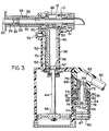
- Figure 3 is a sectional view taken in the same direction as Figure 1, but illustrating the tool in a different condition of adjustment.
- Figure 1 shows a push-pull tool embodying the invention.
- the tool comprises a piston 10 slidably positioned in a cylinder 12 for reciprocal movement in the arrow 14 directions.
- Figure 1 shows the tool at the initiation of a fastener setting operation; piston 10 is just starting to move in a left-to-right direction.
- Figure 3 shows the tool as piston 10 is just starting the return stroke in a right-to-left direction.
- the push-pull tool is designed to permanently affix a multi-piece fastener 16 to work pieces 18.
- the tool-fastener relationship is the same as the relationship shown in U.S. Patent 4,347,728 issued to W. J. Smith.
- the fastener includes a pin 20 having a head 22 positioned against one face of the work piece assembly.
- the shank portion of the pin extends through aligned holes in the work pieces.
- Annular circumferential grooves are formed in the pin surface. At a point near its right end the pin may have a deeper breakneck groove 24 extending therearound.
- a collar 26 is loosely positioned on the pin to engage the left face of the work piece assembly.
- the aforementioned piston 10 is connected to a tubular collet member 33 whose left end is internally formed into an annular cam surface 35.
- a resilient jaw structure 30 is positioned within collet member 33, in a manner more particularly described in above-mentioned U.S. Patent 4,347,728.
- Cylinder 12 is connected to a tubular anvil 32, whose left end face is sized to engage the opposing end face of collar 26.
- rightward motion of the piston causes anvil 32 to forcibly engage the end face of collar 26 as piston 10 exerts a pulling force on pin 20 to prevent relative leftward motion of collar 26 away from the anvil.
- Anvil 32 advances into and along the collar to cause the inner surface of the collar to be swaged into the grooves in pin 20, thereby rigidly locking the multi-piece fastener to work piece 18.
- Fig. 3 shows the pin broken apart (after completion of the collar swaging operation).
- the fluid pressure system for reciprocating piston 10 within cylinder 12 comprises a fluid pumping piston 36 slidably positioned in an elongated pumping cylinder 38. Piston 36 subdivides cylinder 38 into an upper fluid reservoir 40 and a lower fluid reservoir 42. A piston rod 44 extends downwardly through reservoir 44 to a fixed connection with an enlarged air piston 46.
- the two reservoirs vary in volume, depending on the position of piston 36.
- Fastener actuator piston 10 subdivides cylinder 12 into a right hand chamber 47 (Fig. 1) and a left hand chamber 48 (Fig. 3).
- Fluid reservoir 40 is connected to chamber 47 via a horizontal cylindrical passage 50.
- Fluid reservoir 42 is connected to chamber 48 via an elongated vertical passage 52; an angled port 53 connects reservoir 42 to passage 52.
- Chamber 47, passage 50 and reservoir 40 form a closed system for containment of an air-oil foam mixture; a check valve 55 in passage 50 is used to charge air into the chamber 47 and/or the reservoir 40 of this closed system. Oil is charged into the system through a filler opening 51.
- Chamber 48, passage 52 and reservoir 42 form a second closed system for containment of hydraulic fluid (oil).
- a removable threaded fastener provides a filler opening 57 in cylinder 12 to charge oil into the second system.
- the pumping piston 36 can be operated to pump fluids into chambers 47 and 48 thereby driving piston 10 back and forth in cylinder 12.
- Downward motion of piston 36 from the Fig. 1 position to the Fig. 3 position causes oil to be pumped from reservoir 42 through passage 52 into chamber 48.
- an air-oil foam mixture is withdrawn from chamber 47 for movement into reservoir 40.
- Upward motion of piston 36 from the Fig. 3 position to the Fig. 1 position causes an air-oil foam mixture to be pumped from reservoir 40 through passage 50 into chamber 47.
- oil is withdrawn from chamber 48 through passage 52 into reservoir 42.
- the motive force for piston 36 movement is air piston 46.
- the system defined by chamber 47 and reservoir 40 is sized so that chamber 47 displacement is less than the reservoir 40 displacement.
- the volumetric increase in chamber 47 is less than the volumetric decrease in reservoir 40.
- the volumetric decrease in chamber 47 is less than the volumetric increase in reservoir 40.
- the volumetric displacement differential is used to obtain an air-oil foam mixture in the closed system.
- Chamber 47 and reservoir are initially charged with oil (through filler opening 51) with piston 36 in the Fig. 1 position; a sealer plug is applied to the filler opening after of piston 36.
- the volumetric displacement differential is used to obtain an air-oil foam mixture in the closed system.
- Chamber 47 and reservoir 40 are initially charged with oil (through filler opening 51) with piston 36 in the Fig. 1 position; a sealer plug is applied to the filler opening after the oil-changing operation. At this time there is no air in the closed system. However, by cycling piston 36 up and down in cylinder 38 it is possible to draw air into the system through check valve 55. During the first downstroke of piston 36 the system volume increases so that atmospheric air is drawn through check valve 55 to compensate for the volume change; on the upstroke of piston 36 check valve 55 closes so that the drawn-in air is retained within the system. After a few cycles of piston 36 the system will be air-oil filled; thereafter the system will remain closed unless there should be fluid escapage from the system across piston 10 or piston 36.
- Chamber 47 displacement is preferably about twenty-percent less than the reservoir 40 displacement. Therefore, on a volumetric basis the air-oil foam mixture will be about 80% oil and 20% air.
- the displacement differential can be somewhat greater, or somewhat less, than twenty percent, e.g. 30% or 10%.
- the chamber-reservoir dimensions must be such that the foam mixture is predominantly liquid (not gaseous).
- Chamber 48, passage 52 and reservoir 42 form a constant volume system, wherein chamber 48 has the same volumetric displacement as reservoir 42.
- the oil in this system acts as an essentially non-compressible liquid force-transmitter.
- the air-oil foam mixture in the other closed system acts as a slightly compressible force-transmitter.
- an air-oil foam mixture is advantageous in that shock forces tend to be absorbed.
- inertia forces tend to move piston 10 rightwardly at a high rate, especially at the instant when pin 20 is being broken.
- the resulting compression of the air in the air-oil foam mixture tends to exert a snubber force on piston 10, thereby relieving some of the shock loading.
- the air-oil foam mixture is under a high compression loading.
- the foam acts substantially as a liquid, but with some compression due to the air contained therein. Compression of the foam minimizes rebound effects after the piston reaches the Fig. 1 position.
- the described tool has approximately the high force operational mode of a hydraulic tool, but with the shock-cushioning action of an air tool.
- Check valve 55 provides a path for make-up air into the tool.
- the tool does not require a pressure relief valve similar to valve 64 in aforementioned Patent 4,597,263.
- Piston 36 can be operated by any suitable power source.
- Figs. 1 and 3 show the power source of an air piston-cylinder unit constructed generally similar to the corresponding unit in U.S. Patent 4,580,435. Operation of the piston-cylinder unit will be described in a very brief fashion.
- Piston 36 is connected to air piston 46, such that a high pressure on the upper face of piston 46 moves the two pistons from the Fig. 1 condition to the Fig. 3 condition. Conversely, a high air pressure on the lower face of the piston 46 moves the two pistons back to the Fig. 1 condition.
- the air pressures on piston 46 are controlled by a spool valve 64 and manual trigger 72.
- air at 30.7 kg/cm2 (90 p.s.i.) is supplied through hose 60 to space 62 above spool valve 64. Air flows through restriction 66 into space 67 below the spool valve 64. Space 67 may be vented to atmosphere through a passage system that includes a passage 68 (shown in dashed lines) and a connected passage 70.
- a passage system that includes a passage 68 (shown in dashed lines) and a connected passage 70.
- Pressurized air will flow from space 62 through holes 69 in spool valve 64 into an annular groove 73 in annular insert 74.
- a passage 75 conducts the pressurized air into the space above air piston 46, thereby forcing the piston to move downwardly from the Fig. 1 position to the Fig. 3 position.
- the space below piston 46 is vented through a passage system that comprises passage 77, annular groove 79 in insert 74, annular groove 80 in spool valve 64, annular groove 81 in insert 74, passage 82, and porous muffler 83.
- the system is generally similar to that shown in U.S. Patent 4,580,435.
- Air piston 46 can be moved upwardly from the Fig. 3 position to the Fig. 1 position by releasing the manual force on trigger 72. Space 67 below spool valve 64 is thus sealed so that air pressure in space 67 lifts the spool valve to the Fig. 3 position. Pressurized air is supplied to the space below piston 46 through a passage system that includes ports 85 in spool valve 64, groove 79 and passage 77. Air is vented from the space above piston 46 through a passage system that includes passage 75, groove 73 in insert 74, groove 80 in spool valve 64, groove 81, passage 82, and muffler 83.
- the air cylinder unit and control valve system is not part of the present invention.
- the invention is concerned with the fluid system for powering piston 10.
- the air-oil foam mixture in the chamber system defined by chamber 47, passage 50, and reservoir 40.
- Check valve 55 is used to admit atmospheric air into passage 50, to thus provide the air-oil foam mixture.
Landscapes
- Engineering & Computer Science (AREA)
- Mechanical Engineering (AREA)
- Portable Nailing Machines And Staplers (AREA)
Claims (11)
- Schub-Zug-Werkzeug zum Setzen von Befestigern mit
einem das Werkzeug betätigenden Zylinder (12),
einem den Befestiger betätigenden Kolben (10), der gleitend verschiebbar im Zylinder (12) angeordnet ist und diesen zu einer ersten Kammer (48) und einer zweiten Kammer (47) unterteilt,
einem ersten und einem von diesem separaten zweiten Fluid und
einer Pumpeinrichtung (36) mit einem Vorwärtshub zum Pumpen des ersten Fluids in die erste Kammer (48) und gleichzeitigem Abziehen des zweiten Fluids aus der zweiten Kammer (47), um dadurch den Kolben (10) in einer ersten Richtung zu bewegen,
wobei die Pumpeinrichtung (36) einen Rückhub zum Zurückpumpen des zweiten Fluids in die zweite Kammer (47) und zum gleichzeitigen Abziehen des ersten Fluids aus der ersten Kammer (48) aufweist, um dadurch den Kolben (10) in einer zweiten Richtung zu bewegen,
dadurch gekennzeichnet, daß
das erste Fluid eine Flüssigkeit und das zweite Fluid ein Gas/Flüssigkeit-Schaumgemisch ist und daß
eine selbsttätig arbeitende Gaseinlaßeinrichtung (55) betrieblich mit der Pumpeinrichtung (36) verbunden ist, um selbsttätig Gas in die zweite Kammer (47) einzulassen, das sich mit der Flüssigkeit in der zweiten Kammer mischen soll, um das Gas/Flüssigkeit-Schaumgemisch zu bilden. - Werkzeug nach Anspruch 1 mit einem zweiten Behälter (40), der mit der zweiten Kammer (47) durch einen zweiten Kanal verbunden ist, wobei das Gas/Flüssigkeit-Schaumgemisch ein Luft/Öl-Schaumgemisch und die Fluidverdrängung in der zweiten Kammer (47) geringer als die im zweiten Behälter (40) ist und wobei die selbsttätig arbeitende Gaseinlaßeinrichtung eine einrichtung (55) aufweist, die betrieblich entsprechend dem Unterschied der Fluidverdrängung zwischen der zweiten Kammer (47) und dem zweiten Behälter (40) Umluft in den zweiten Kanal (50) einläßt.
- Werkzeug nach Anspruch 1, bei dem das Gas/Flüssigkeit-Schaumgemisch zu 70% bis 90% aus Flüssigkeit, Rest Gas, besteht.
- Werkzeug nach Anspruch 1, bei dem das Gas/Flüssigkeit-Gemisch aus etwa 80% Flüssigkeit und 20% Gas besteht.
- Werkzeug nach Anspruch 1, bei dem die selbsttätig arbeitende Gaseinlaßeinrichtung zum Einlassen von Gas in die zweite Kammer (47) ein Rückschlagventil (55) aufweist, das betrieblich externes Gas aus einer externen Quelle in die zweite Kammer (47) einläßt, falls in der zweiten Kammer (47) ein geringerer Druck als der externe Druck der externen Quelle herrscht.
- Schub-Zug-Werkzeug zum Setzen von Befestigern mit
einem das Werkzeug betätigenden ersten Zylinder (12),
einem Befestigersetzkolben (10), der gleitend verschiebbar im Zylinder (12) angeordnet ist und diesen zu einer ersten Kammer (48) und einer zweiten Kammer (47) unterteilt,
einem ersten und einem separaten zweiten Fluid,
einer Pumpeinrichtung mit einem Fluidpumpzylinder (38) und einem Pumpkolben (36), der gleitend verschiebbar im Pumpzylinder (38) angeordnet ist und diesen zu einem ersten Fluidbehälter (42) und einem zweiten Fluidbehälter (40) unterteilt,
einer ersten Kanaleinrichtung (52), die die erste Kammer (48) mit dem ersten Fluidbehälter (42) verbindet,
einer zweiten Kanaleinrichtung (50), die die zweite Kammer (47) mit dem zweiten Fluidbehälter (40) verbindet, und mit
einer Betätigungseinrichtung (46), die den Pumpkolben (36) über einen Vorwärtshub, in dem zweites Fluid aus der zweiten Kanmnmer (47) über die zweite Kanaleinrichtung (50) in den zweiten Behälter (40) gepumpt wird, und über einen Rückhub bewegt, in dem zweites Fluid aus dem zweiten Behälter (40) über die zweite Kanaleinrichtung (50) zurück in die zweite Kammer (47) gepumpt wird,
wobei der Pumpkolben (36) im Vorwärtshub betriblich erstes Fluid aus dem ersten Fluidbehälter (42) über die erste Kanaleinrichtung (52) in die erste Kammer (48) pumpt und im Rückhub erstes Fluid aus der ersten Kammer (48) über die erste Kanaleinrichtung (52) in den erste Fluidbehälter zieht,
dadurch gekennzeichnet, daß
das erste Fluid eine Flüssigkeit ist, die sich in der ersten Kammer (48) und dem zugehörigen Behälter (42) befindet,
das zweite Fluid ein Gas/Flüssigkeit-Schaumgemisch ist, das sich in der zweiten Kammer (47) und dem zweiten Behälter (40) befindet, und daß
eine selbsttätig arbeitende Gaseinlaßeinrichtung (55) betrieblich mit der Pumpeinrichtung (36) verbunden ist, um selbsttätig Gas in den zweiten Fluidbehälter (40) einzulassen, in dem es sich zur Bildung des Gas/Flüssigkeit-Schaumgemisches mit der Flüssigkeit in diesem mischen soll. - Werkzeug nach Anspruch 6, bei dem die selbsttätig arbeitende Gaseinlaßeinrichtung ein Rückschlagventil (55) aufweist, das mit der zweiten Kanaleinrichtung (50) verbunden ist, um Umluft in diese einzulassen, falls der Druck in ihr unter den Umluftdruck fällt.
- Werkzeug nach Anspruch 6, bei dem die Fluidverdrängung der zweiten Kammer (47) geringer als die des zweiten Behälters (40) ist.
- Werkzeug nach Anspruch 6, bei dem die Fluidverdrängung der zweiten Kammer (47) geringer als die des zweiten Behälters (40) ist und die selbsttätig arbeitende Gaseinlaßeinrichtung ein Rückschlagventil (55) aufweist, das betrieblich entsprechend dem Unterschied der Fluidverdrängung zwischen der zweiten Kammer (47) und dem zweiten Behälter (40) Umluft in die zweite Kanaleinrichtung (50) einläßt.
- Werkzeug nach Anspruch 9, bei dem die Verdrängung der zweiten Kammer (47) zwischen 10 % und 30 % geringer ist als die des zweiten Behälters (40).
- Werkzeug nach Anspruch 10, bei dem die Verdrängung der zweiten Kammer (47) etwa 20 % geringer ist als die des zweiten Behälters (40).
Applications Claiming Priority (3)
| Application Number | Priority Date | Filing Date | Title |
|---|---|---|---|
| US07/285,469 US4878372A (en) | 1988-12-16 | 1988-12-16 | Shock-absorbing fluid-actuated fastener installation tool |
| US285469 | 1988-12-16 | ||
| PCT/US1989/005473 WO1990006826A1 (en) | 1988-12-16 | 1989-12-04 | Shock-absorbing fluid-actuated fastener installation tool |
Publications (2)
| Publication Number | Publication Date |
|---|---|
| EP0449945A1 EP0449945A1 (de) | 1991-10-09 |
| EP0449945B1 true EP0449945B1 (de) | 1995-10-18 |
Family
ID=23094371
Family Applications (1)
| Application Number | Title | Priority Date | Filing Date |
|---|---|---|---|
| EP90901291A Expired - Lifetime EP0449945B1 (de) | 1988-12-16 | 1989-12-04 | Stossdämpfendes hydraulisches werkzeug zum setzen von befestigungselementen |
Country Status (5)
| Country | Link |
|---|---|
| US (1) | US4878372A (de) |
| EP (1) | EP0449945B1 (de) |
| JP (1) | JP2809502B2 (de) |
| DE (1) | DE68924597T2 (de) |
| WO (1) | WO1990006826A1 (de) |
Families Citing this family (35)
| Publication number | Priority date | Publication date | Assignee | Title |
|---|---|---|---|---|
| US4964292A (en) * | 1988-12-16 | 1990-10-23 | Huck Manufacturing Company | Shock-absorbing fluid-actuated pressure system |
| IT1235969B (it) * | 1989-11-17 | 1992-12-15 | Far Snc Di Generali Giacomo & | Dispositivo per il recupero della pressione fluidodinamica in particolare per macchine rivettatrici |
| US5031508A (en) * | 1990-09-05 | 1991-07-16 | Emhart Inc. | Rivet setting tool |
| USD369731S (en) | 1993-12-10 | 1996-05-14 | Huck International, Inc. | Installation tool for setting pull type fasteners |
| USD363421S (en) | 1993-12-10 | 1995-10-24 | Huck International, Inc. | Installation tool for setting pull type fasteners |
| GB9403220D0 (en) * | 1994-02-19 | 1994-04-13 | Embart Inc | Rivet setting tool |
| US5598619A (en) * | 1994-05-09 | 1997-02-04 | Huck International, Inc. | Hydraulic installation tool |
| US5519926A (en) * | 1994-05-09 | 1996-05-28 | Huck International, Inc. | Nose assembly for hydraulic installation tool |
| US5485727A (en) * | 1994-11-14 | 1996-01-23 | Gbp Corporation | Fastener installation tool |
| US6182345B1 (en) | 1999-05-20 | 2001-02-06 | Huck International, Inc. | Gripping jaw assembly with in phase jaws |
| US6233802B1 (en) | 1999-08-06 | 2001-05-22 | Huck International, Inc. | Low swage load fastener and fastening system |
| US6325582B1 (en) | 2000-07-06 | 2001-12-04 | Huck International, Inc. | Swage type fastener with low swage load |
| USD462883S1 (en) | 2001-02-14 | 2002-09-17 | Emhart Llc | Rivet setting tool |
| CZ12144U1 (cs) * | 2002-02-18 | 2002-03-28 | Ms Nářadí, S.R.O. | Upínací spoj výměnného trnu a taľného čepu nýtovacího nástroje a pouľití tohoto upínacího spoje pro ruční nýtovací nástroj |
| US7146698B2 (en) * | 2002-02-18 | 2006-12-12 | Masterfix Products B.V. | Hand-held riveting tool |
| US6739170B1 (en) | 2003-03-17 | 2004-05-25 | Huck International, Inc. | Offset nose assembly with improved deflector and guard assemblies |
| WO2005069830A2 (en) * | 2004-01-15 | 2005-08-04 | Fulbright David J | A fastner installaton system |
| US7677853B2 (en) * | 2004-08-30 | 2010-03-16 | Acument Intellectual Properties, Llc | Multi-lobular lockbolt and system |
| US7677852B2 (en) * | 2004-08-30 | 2010-03-16 | Acument Intellectual Properties, Llc | Multi-lobular lockbolt |
| US20070295779A1 (en) * | 2005-01-13 | 2007-12-27 | Fulbright David J | Fastener installation system |
| US7293339B2 (en) * | 2005-06-29 | 2007-11-13 | Huck International, Inc. | Low swage load fastening system and method |
| EP2251118B1 (de) | 2006-11-03 | 2013-01-02 | Huck International, Inc. | Klemmklauenanordnung für eine Stauchverbindungsvorrichtung mit niedriger Umformlast |
| US7891924B2 (en) * | 2006-11-03 | 2011-02-22 | Huck International, Inc. | Low swage load fastening system and method |
| US8727685B2 (en) | 2012-02-02 | 2014-05-20 | Alcoa Inc. | Swage indicating collar |
| US10138909B2 (en) * | 2013-05-09 | 2018-11-27 | Eaton Intelligent Power, Ltd | Multi-cylinder assembly |
| US9908233B2 (en) | 2013-07-09 | 2018-03-06 | Arconic Inc. | Fastener installation tool |
| US9248494B2 (en) * | 2013-09-10 | 2016-02-02 | Yu-Tang Lin | Rivet gun having buffer device |
| WO2015041721A1 (en) | 2013-09-19 | 2015-03-26 | Alcoa Inc. | Lock bolt collar with high standoff internal bead |
| JP6220974B2 (ja) | 2014-01-30 | 2017-10-25 | アルコニック インコーポレイテッドArconic Inc. | ファスナ及びファスナ取付具 |
| US10087972B2 (en) | 2014-01-30 | 2018-10-02 | Arconic Inc. | Fastener and fastener installation tool |
| ES2673905T3 (es) * | 2014-02-26 | 2018-06-26 | Arconic Inc. | Herramienta de instalación de elementos de fijación con manguitos concéntricos internos |
| WO2015168063A1 (en) | 2014-04-29 | 2015-11-05 | Alcoa Inc. | Swage lock fasteners |
| US10215210B2 (en) | 2015-11-17 | 2019-02-26 | Arconic Inc. | Blind fastener |
| US10260547B2 (en) | 2016-04-05 | 2019-04-16 | Arconic Inc. | Lockbolt fastening system |
| US10710146B2 (en) | 2016-10-20 | 2020-07-14 | Arconic Inc. | Fastener and fastening system |
Family Cites Families (13)
| Publication number | Priority date | Publication date | Assignee | Title |
|---|---|---|---|---|
| DE1300504B (de) * | 1962-04-17 | 1969-08-07 | Textron Ind Inc | Druckmittelbetaetigtes Werkzeug zum Anbringen von Befestigungsmitteln, insbesondere von Scherzugbolzen |
| JPS5641993B2 (de) * | 1974-03-04 | 1981-10-01 | ||
| GB1479375A (en) * | 1974-05-25 | 1977-07-13 | Gesipa Blindentechnik Gmbh | Pneumatic-mechanical blind riveting tool |
| JPS5952593B2 (ja) * | 1974-12-28 | 1984-12-20 | 松下電器産業株式会社 | 磁気録画再生法 |
| GB1569569A (en) * | 1976-04-12 | 1980-06-18 | Avdel Ltd | Hydraulic pressure generation apparatus |
| US4118969A (en) * | 1977-07-27 | 1978-10-10 | Huck Manufacturing Company | Double action fastener installation tool for blind rivets and the like |
| JPS554851A (en) * | 1978-06-26 | 1980-01-14 | Matsushita Electric Industrial Co Ltd | Planar heater |
| US4347728A (en) * | 1979-05-30 | 1982-09-07 | Huck Manufacturing Company | Apparatus and system for setting fasteners |
| US4597263A (en) * | 1979-10-18 | 1986-07-01 | Huck Manufacturing Company | Pull type installation tool |
| JPS58145089A (ja) * | 1982-02-24 | 1983-08-29 | 株式会社日立ホームテック | 埋設用面状発熱体 |
| US4633068A (en) * | 1984-02-15 | 1986-12-30 | Flexwatt Corporation | Electrical heating device |
| US4580435A (en) * | 1984-03-05 | 1986-04-08 | Huck Manufacturing Company | Installation tool for pull type fasteners |
| JPS62285391A (ja) * | 1986-06-03 | 1987-12-11 | 株式会社 サ−モミツク | 面状発熱体 |
-
1988
- 1988-12-16 US US07/285,469 patent/US4878372A/en not_active Expired - Fee Related
-
1989
- 1989-12-04 EP EP90901291A patent/EP0449945B1/de not_active Expired - Lifetime
- 1989-12-04 DE DE68924597T patent/DE68924597T2/de not_active Expired - Fee Related
- 1989-12-04 WO PCT/US1989/005473 patent/WO1990006826A1/en not_active Ceased
- 1989-12-04 JP JP2501377A patent/JP2809502B2/ja not_active Expired - Lifetime
Also Published As
| Publication number | Publication date |
|---|---|
| DE68924597D1 (de) | 1995-11-23 |
| JP2809502B2 (ja) | 1998-10-08 |
| US4878372A (en) | 1989-11-07 |
| DE68924597T2 (de) | 1996-04-04 |
| WO1990006826A1 (en) | 1990-06-28 |
| EP0449945A1 (de) | 1991-10-09 |
| JPH04502281A (ja) | 1992-04-23 |
Similar Documents
| Publication | Publication Date | Title |
|---|---|---|
| US4878372A (en) | Shock-absorbing fluid-actuated fastener installation tool | |
| US4964292A (en) | Shock-absorbing fluid-actuated pressure system | |
| US5377488A (en) | Hydro-pneumatic pressure transformer | |
| US4599861A (en) | Internal combustion hydraulic engine | |
| US4300351A (en) | Boosted hydro-pneumatic drive | |
| US2526956A (en) | Fluid actuated reciprocating tool | |
| EP0154280B1 (de) | Werkzeug zum Setzen von Befestigungselementen durch Einziehen | |
| US4034817A (en) | Impact tool | |
| US4263801A (en) | Hydraulic riveter | |
| US5381661A (en) | Hydraulic pressure transformer | |
| JPH0649276B2 (ja) | 空気式締結装置 | |
| US3803840A (en) | Power driver device | |
| CA1164770A (en) | Hydraulic cylinder extending in three force modes | |
| US3687008A (en) | Pressure fluid controlled reciprocating mechanism | |
| US3638534A (en) | Fastener driving tool with improved pneumatic piston retaining means | |
| US3908373A (en) | High energy rate actuator | |
| JPH0570722B2 (de) | ||
| US5064005A (en) | Impact hammer and control arrangement therefor | |
| US5013198A (en) | Air-hydraulic pump with auxiliary pumping means | |
| US5072501A (en) | Device for restoring lost fluid pressure particularly in riveting machines | |
| US3404603A (en) | Hydraulically operated tools | |
| US20050144944A1 (en) | Air-to-oil intensifying cylinder | |
| JP5245667B2 (ja) | 打込機 | |
| US3412645A (en) | Pneumatic motor of the reciprocable type | |
| RU2069741C1 (ru) | Устройство для механической перфорации скважин |
Legal Events
| Date | Code | Title | Description |
|---|---|---|---|
| PUAI | Public reference made under article 153(3) epc to a published international application that has entered the european phase |
Free format text: ORIGINAL CODE: 0009012 |
|
| 17P | Request for examination filed |
Effective date: 19910603 |
|
| AK | Designated contracting states |
Kind code of ref document: A1 Designated state(s): DE FR GB |
|
| RAP1 | Party data changed (applicant data changed or rights of an application transferred) |
Owner name: HUCK INTERNATIONAL, INC. |
|
| 17Q | First examination report despatched |
Effective date: 19921208 |
|
| GRAA | (expected) grant |
Free format text: ORIGINAL CODE: 0009210 |
|
| AK | Designated contracting states |
Kind code of ref document: B1 Designated state(s): DE FR GB |
|
| REF | Corresponds to: |
Ref document number: 68924597 Country of ref document: DE Date of ref document: 19951123 |
|
| ET | Fr: translation filed | ||
| PLBE | No opposition filed within time limit |
Free format text: ORIGINAL CODE: 0009261 |
|
| STAA | Information on the status of an ep patent application or granted ep patent |
Free format text: STATUS: NO OPPOSITION FILED WITHIN TIME LIMIT |
|
| 26N | No opposition filed | ||
| PGFP | Annual fee paid to national office [announced via postgrant information from national office to epo] |
Ref country code: FR Payment date: 19991117 Year of fee payment: 11 |
|
| PGFP | Annual fee paid to national office [announced via postgrant information from national office to epo] |
Ref country code: GB Payment date: 19991118 Year of fee payment: 11 Ref country code: DE Payment date: 19991118 Year of fee payment: 11 |
|
| PG25 | Lapsed in a contracting state [announced via postgrant information from national office to epo] |
Ref country code: GB Free format text: LAPSE BECAUSE OF NON-PAYMENT OF DUE FEES Effective date: 20001204 |
|
| GBPC | Gb: european patent ceased through non-payment of renewal fee |
Effective date: 20001204 |
|
| PG25 | Lapsed in a contracting state [announced via postgrant information from national office to epo] |
Ref country code: FR Free format text: LAPSE BECAUSE OF NON-PAYMENT OF DUE FEES Effective date: 20010831 |
|
| REG | Reference to a national code |
Ref country code: FR Ref legal event code: ST |
|
| PG25 | Lapsed in a contracting state [announced via postgrant information from national office to epo] |
Ref country code: DE Free format text: LAPSE BECAUSE OF NON-PAYMENT OF DUE FEES Effective date: 20011002 |