EP0449946B1 - Procede et appareil de compostage a assistance pneumatique pour faciliter le mouvement de matiere organique - Google Patents
Procede et appareil de compostage a assistance pneumatique pour faciliter le mouvement de matiere organique Download PDFInfo
- Publication number
- EP0449946B1 EP0449946B1 EP19900901294 EP90901294A EP0449946B1 EP 0449946 B1 EP0449946 B1 EP 0449946B1 EP 19900901294 EP19900901294 EP 19900901294 EP 90901294 A EP90901294 A EP 90901294A EP 0449946 B1 EP0449946 B1 EP 0449946B1
- Authority
- EP
- European Patent Office
- Prior art keywords
- organic matter
- vessel
- air
- chamber
- surge
- Prior art date
- Legal status (The legal status is an assumption and is not a legal conclusion. Google has not performed a legal analysis and makes no representation as to the accuracy of the status listed.)
- Expired - Lifetime
Links
- 239000005416 organic matter Substances 0.000 title claims abstract description 110
- 238000009264 composting Methods 0.000 title claims abstract description 50
- 238000000034 method Methods 0.000 title claims abstract description 18
- 230000000694 effects Effects 0.000 claims abstract description 12
- 238000000354 decomposition reaction Methods 0.000 claims abstract description 9
- 230000009471 action Effects 0.000 claims abstract description 3
- 238000005056 compaction Methods 0.000 claims description 20
- 238000000151 deposition Methods 0.000 claims 1
- 239000000463 material Substances 0.000 abstract description 15
- 239000003570 air Substances 0.000 description 160
- 238000005273 aeration Methods 0.000 description 71
- 238000001816 cooling Methods 0.000 description 9
- 239000010802 sludge Substances 0.000 description 9
- 239000002361 compost Substances 0.000 description 7
- 230000035515 penetration Effects 0.000 description 7
- 230000008569 process Effects 0.000 description 7
- 230000008901 benefit Effects 0.000 description 6
- 239000012530 fluid Substances 0.000 description 4
- 238000004891 communication Methods 0.000 description 3
- 230000009467 reduction Effects 0.000 description 3
- 238000004065 wastewater treatment Methods 0.000 description 3
- 238000010276 construction Methods 0.000 description 2
- 230000003247 decreasing effect Effects 0.000 description 2
- 238000005265 energy consumption Methods 0.000 description 2
- 238000002347 injection Methods 0.000 description 2
- 239000007924 injection Substances 0.000 description 2
- 239000000523 sample Substances 0.000 description 2
- 239000002364 soil amendment Substances 0.000 description 2
- XLYOFNOQVPJJNP-UHFFFAOYSA-N water Substances O XLYOFNOQVPJJNP-UHFFFAOYSA-N 0.000 description 2
- 238000009825 accumulation Methods 0.000 description 1
- 239000012080 ambient air Substances 0.000 description 1
- 230000001276 controlling effect Effects 0.000 description 1
- 238000001035 drying Methods 0.000 description 1
- 230000005484 gravity Effects 0.000 description 1
- 230000006872 improvement Effects 0.000 description 1
- 230000007246 mechanism Effects 0.000 description 1
- 239000011368 organic material Substances 0.000 description 1
- 239000010815 organic waste Substances 0.000 description 1
- 244000052769 pathogen Species 0.000 description 1
- 238000002360 preparation method Methods 0.000 description 1
- 230000001105 regulatory effect Effects 0.000 description 1
- 239000007787 solid Substances 0.000 description 1
- 210000003462 vein Anatomy 0.000 description 1
Images
Classifications
-
- C—CHEMISTRY; METALLURGY
- C05—FERTILISERS; MANUFACTURE THEREOF
- C05F—ORGANIC FERTILISERS NOT COVERED BY SUBCLASSES C05B, C05C, e.g. FERTILISERS FROM WASTE OR REFUSE
- C05F17/00—Preparation of fertilisers characterised by biological or biochemical treatment steps, e.g. composting or fermentation
- C05F17/90—Apparatus therefor
- C05F17/921—Devices in which the material is conveyed essentially horizontally between inlet and discharge means
- C05F17/936—Tunnels
-
- C—CHEMISTRY; METALLURGY
- C05—FERTILISERS; MANUFACTURE THEREOF
- C05F—ORGANIC FERTILISERS NOT COVERED BY SUBCLASSES C05B, C05C, e.g. FERTILISERS FROM WASTE OR REFUSE
- C05F17/00—Preparation of fertilisers characterised by biological or biochemical treatment steps, e.g. composting or fermentation
- C05F17/90—Apparatus therefor
- C05F17/964—Constructional parts, e.g. floors, covers or doors
-
- Y—GENERAL TAGGING OF NEW TECHNOLOGICAL DEVELOPMENTS; GENERAL TAGGING OF CROSS-SECTIONAL TECHNOLOGIES SPANNING OVER SEVERAL SECTIONS OF THE IPC; TECHNICAL SUBJECTS COVERED BY FORMER USPC CROSS-REFERENCE ART COLLECTIONS [XRACs] AND DIGESTS
- Y02—TECHNOLOGIES OR APPLICATIONS FOR MITIGATION OR ADAPTATION AGAINST CLIMATE CHANGE
- Y02P—CLIMATE CHANGE MITIGATION TECHNOLOGIES IN THE PRODUCTION OR PROCESSING OF GOODS
- Y02P20/00—Technologies relating to chemical industry
- Y02P20/141—Feedstock
- Y02P20/145—Feedstock the feedstock being materials of biological origin
-
- Y—GENERAL TAGGING OF NEW TECHNOLOGICAL DEVELOPMENTS; GENERAL TAGGING OF CROSS-SECTIONAL TECHNOLOGIES SPANNING OVER SEVERAL SECTIONS OF THE IPC; TECHNICAL SUBJECTS COVERED BY FORMER USPC CROSS-REFERENCE ART COLLECTIONS [XRACs] AND DIGESTS
- Y02—TECHNOLOGIES OR APPLICATIONS FOR MITIGATION OR ADAPTATION AGAINST CLIMATE CHANGE
- Y02W—CLIMATE CHANGE MITIGATION TECHNOLOGIES RELATED TO WASTEWATER TREATMENT OR WASTE MANAGEMENT
- Y02W30/00—Technologies for solid waste management
- Y02W30/40—Bio-organic fraction processing; Production of fertilisers from the organic fraction of waste or refuse
-
- Y—GENERAL TAGGING OF NEW TECHNOLOGICAL DEVELOPMENTS; GENERAL TAGGING OF CROSS-SECTIONAL TECHNOLOGIES SPANNING OVER SEVERAL SECTIONS OF THE IPC; TECHNICAL SUBJECTS COVERED BY FORMER USPC CROSS-REFERENCE ART COLLECTIONS [XRACs] AND DIGESTS
- Y10—TECHNICAL SUBJECTS COVERED BY FORMER USPC
- Y10S—TECHNICAL SUBJECTS COVERED BY FORMER USPC CROSS-REFERENCE ART COLLECTIONS [XRACs] AND DIGESTS
- Y10S435/00—Chemistry: molecular biology and microbiology
- Y10S435/818—Aeration or oxygen transfer technique
Definitions
- the invention relates to a method and apparatus for composting organic matter according to the pre-characterizing part of claims 1 and 3, respectively.
- compaction of the mass of organic matter which in turn leads to a high pressure drop in the aeration air being injected into the mass of organic matter, requires cooling of aeration air to provide cooling of the mass of organic matter.
- the amount of energy required for injection of aeration air into the organic matter which occurs over a relatively long period of time, could also be significantly reduced.
- Both the temperature and the pressure of the aeration air are interrelated, in that increased pressure results in an increased temperature of the aeration air. During hot weather, the temperature increase over ambient temperature due to pressurization of the aeration air may cause the temperature of the aeration air to exceed the maximum safe level for aerobic decomposition. To counteract this with air cooling equipment is expensive, both in terms of capital investment and operating costs.
- the present invention also provides a composting apparatus in which operating costs and energy consumption will be reduced as compared with known systems.
- the temperature of aeration air circulating through the organic matter being composed may be reduced without the use of cooling equipment.
- This present invention allows the use of a larger composting vessel than has hereto been feasible without increasing the degree of compaction of the compost produced in the larger vessel.
- the present invention provides a composting apparatus and method for accelerated aerobic decomposition of organic matter in which organic matter is deposited into a chamber of a vessel.
- the vessel includes an inlet to the interior chamber of the vessel and an outlet from the chamber.
- a ram is coupled with the vessel and is movable within an inlet end region of the chamber. This exerts a compressive force on the organic matter.
- organic matter deposited in the vessel through the inlet may be moved through the chamber toward the outlet by the action of the ram.
- a set of orifices in the vessel introduce pressurized air into the vessel. Normally, such pressurized air will be introduced at a relatively low intensity for aeration purposes.
- a surge of pressurized air is delivered into the chamber, the surge of pressurized air being of such intensity as to effect movement of the organic matter through the chamber at an application of compressive force by the ram which is substantially less than the compressive force required to move the organic matter absent the surge of air. This produces a substantially less dense mass of organic matter than would be produced if no such surge of pressurized air were delivered.
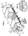
- Reference numeral 10 refers generally to a composting apparatus according to the particular exemplary embodiment of the present invention as shown and described herein.
- Composting apparatus 10 includes a hollow vessel 12 defined by walls 14.
- the vessel has a rectangular cross section such that walls 14 include a floor 16, a top wall 17, and side walls 18 extending in parallel fashion between the floor 16 and top wall 17.
- Walls 14 define a chamber 20 within vessel 12.
- vessel 12 and its internal chamber 20 are elongated so as to take the form of a conduit.
- an inlet 22 having an inlet door 24 and an infeed conveyor 26, whereby inlet 22 in conjunction with infeed conveyor 26 permits communication with chamber 20 within the vessel 12.
- outlet 28 At the opposite end of vessel 12 is an outlet 28.
- a ram 30 driven by a set of hydraulic cylinders 32.
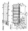
- Hydraulic cylinders 32 are actuated by a source of pressurized hydraulic fluid 34 shown schematically in Fig. 4, which pressure source 34 communicates with hydraulic cylinders 32 via hydraulic fluid lines 35.
- the source of pressurized hydraulic fluid 34 will take the form of a motor-driven hydraulic pump feeding hydraulic fluid in the form of oil to hydraulic cylinders 32 via hydraulic line 35 to move the ram 30.
- Organic matter such as sludge from a waste water treatment system, is fed into the composting apparatus 10 via infeed conveyor 26 in a direction shown by arrow 37 (Fig. 1.)
- the organic matter is fed into chamber 20 at the end thereof adjacent inlet 22 and is deposited in front of ram 30.
- Hydraulic cylinders 32 are actuated to move ram 30 in a direction toward outlet 28 in order to advance the charge of organic matter 36 through composting apparatus 10.
- the advance of ram 30 is shown in phantom lines in Fig. 3.
- the distance between the retracted position of ram 30 as shown in solid lines in Fig. 3 and the fully advanced position as shown in phantom lines in Fig. 3 represents the volume of one charge of organic matter 36 fed into the composting apparatus 10 during one infeed operation. After such an infeed operation, ram 30 is retracted to the solid line position shown in Fig. 3 in preparation for the next infeed operation.
- inlet door 24 moves horizontally behind the ram 30 as the ram 30 moves forward in its stroke to push organic matter 36 through chamber 20 of vessel 12.
- inlet door 24 moves horizontally behind the ram 30 as the ram 30 moves forward in its stroke to push organic matter 36 through chamber 20 of vessel 12.
- Vessel 12 includes in the floor 16 a set of floor-mounted diffusers or orifices 40 distributed along virtually the entire length of vessel 12. These diffusers 40 communicate with chamber 20 of vessel 12 to permit pressurized air to be injected into chamber 20. The air injection is accomplished via air passages 42 in floor 16, which air passages are fed by an air header 43 disposed outlet vessel 12. Thus, air header 43 communicates with the series of air passages 42 which, in turn, communicates with diffusers 40 for injecting air into chamber 20.
- two separate sources of pressurized air communicating with the header 43, passages 42, and diffusers 40 will be described.
- One source provides air for effecting aeration of the organic matter 36 to convert it to compost in a known manner.
- the other source provides for a surge of pressurized air through the same header 43, passages 42, and diffusers 40 to assist in the movement of organic matter 36 through the vessel 12.
- two separate sources one for aeration air, the other for surge air
- the surge air is provided by a source in the form of a compressor system 44 which includes a motor 45, preferably an electric motor, driving an air compressor 46 which, in turn, feeds an accumulator 47 which stores a substantial quantity of pressurized air.
- a line 48 extends from the accumulator 47 to the air header 43 to provide a surge of air to header 43 and thus to air passages 42 and diffusers 40.
- a check valve 49 isolates the source of surge air from the source of aeration air when surge air is introduced into air header 43.
- aeration air such air is generated by a blower 51 driven by electric motor 52.
- Aeration air is fed past check valve 49 into air header 43 to then pass through air passages 42 in floor 16 of chamber 20 and thence through diffusers 40 for aeration of the organic matter 36 to aid in composting.
- a selected portion of the set of diffusers or orifices 40 may act as suction orifices or inlets for return of aeration air which has been introduced into the organic matter 36 by others of the diffusers or orifices 40. By providing that some of the orifices 40 act as air returns, circulation through the organic matter 36 may be improved.
- This aeration air return is accomplished via a suction fan 54 driven by a motor 56.
- Suction fan 54 communicates with the suction header 58 which, in turn, selectively communicates with a certain portion of the air passages 42.
- air passages 42 then act as air returns for drawing aeration air from organic matter 36 to enhance circulation of aeration air.
- valves 60 preferably in the form of solenoid valves.
- a valve 60 will be disposed between each air passage 42 and the air header 43 and suction header 58.
- each valve 60 determines whether the associated air passage 42 communicates with the air header 43 (in which case that air passage will receive pressurized air so that the associated orifices 40 act as diffusers for introducing air into chamber 20) or will communicate with suction header 58 (in which case that air passage 42 and its associated orifices 40 act as air returns for withdrawing aeration air from chamber 20.)
- the particular pattern of which air passages 42 and associates orifices 40 are placed under suction and which are placed under pressure may vary from case to case depending on the particular organic matter 36 being composted and the particular conditions under which the composting takes place. For instance, under some circumstances, the best results may be obtained by placing all of the air passages 42 and orifices 40 under pressure.
- air passages 42 and orifices 40 will be placed under suction via actuation of valves 60 to effect communication with suction header 58.
- An alternating pattern may be used such that an air passage 42 under pressure is followed by an air passage 42 under suction, followed by another air passage 42 under pressure, and so on.
- separate zones of pressure and suction diffusers may be provided. In the particular exemplary embodiment shown and described, there are five zones of four air passages per zone. Each zone corresponds generally with a charge of material fed into vessel 12 by one infeed operation and one stroke of ram 30. Thus, one such zone may be put under pressure, the next under suction, and so on in an alternating fashion.
- the surge-delivering system of the present invention accomplishes the delivery into the vessel 12, at least at certain times when ram 30 is acting upon organic matter 36, of a surge of pressurized air of such intensity as to effect movement of the organic matter 36 through chamber 20 with substantially less force from the ram 30, and thus substantially less compaction of organic matter 36 than if no such surge were provided.
- the surge-delivering system includes a surge-producing control 62 connected with a valve 63 in a line 48 which extends from the accumulator 47 of compressor 44 to the air header 43.
- surge-producing control 62 which preferably takes the form of an electronic controller, sends a signal to valve 63, which preferably takes the form of a solenoid valve, to open, a surge of air from compressor system 44 and accumulator 47 is introduced into air header 43 to, in turn, send a surge of air through air passages 42 and floor-mounted orifices 40.
- aeration-producing control 64 is coupled with the blower 51 which produces aeration air, and more specifically with the motor 52 of that blower.
- Aeration-producing control 64 is preferably electronic and sends electrical signals to motor 52 of blower 51 to regulate the intensity of aeration air produced by blower 51.
- both surge-producing control 62 and aeration-producing control 64 will be housed together in a single unit constituting an air controller 65 schematically shown by broken lines in Fig. 4.
- air controller 65 controls both the delivery of aeration air and the delivery of surge air.
- both aeration air and surge air may come from the same source, i.e., a single compressor or blower. That single source will be controlled by the air controller 65, which includes both the surge-producing control 62 and the aeration-producing control 64.
- the aeration-producing control 62 can be as simple as a relatively low range of rheostat settings on controller 65 to produce a relatively low intensity of pressurized air for effecting aeration and, in the same vein, the surge-producing control can be as simple as a relatively high range of rheostat settings in the controller 65 to produce a higher intensity output from the blower or compressor for producing the requisite surge of pressurized air.
- suction-producing motor control 66 for energizing motor 56 of suction fan 54 and for regulating its operation.
- suction-producing motor control 66 is electronic.
- each of the controls 62, 64, 66 be coupled with a master controller 70 shown schematically in Fig. 4.
- Master controller 70 acts as a central station from which the delivery of aeration air, surge air, and suction air may be controlled.
- master controller 70 may consist of manually operable switches and dials to be operated by a human controller, or it may be an automated controller operating according to a predetermined program utilizing analog or digital electronics, or it may be a hybrid system utilizing both manual switches and dials as well as a predetermined control program.
- Master controller 70 is coupled with surge-producing control 62 via line 72.
- surge-producing control 62 is coupled with valve 63 of the compressor system 44 via line 73.
- Master controller 70 is connected to the aeration system via line 74 running to aeration-producing control 64.
- aeration-producing control 64 is coupled to motor 52 of blower 51 via line 75.
- the master controller is preferably also coupled with valve 60 which determines the pattern of which air passages 42 and orifices 40 are under pressure and which, if any, are under suction.
- controller 70 provides the appropriate signals to valves 60 over a line 76 (Fig. 4.)
- Master controller 70 controls the source of suction by sending signals to suction-producing control 66 over line 78.
- suction-producing control 66 is coupled with motor 56 of suction fan 54 by line 79.
- Master control 70 also controls the operation of the ram 30 which is driven by hydraulic cylinders 32. Further, master controller 70 requires feedback from the hydraulic system for driving the ram 30 in order to effect control of the surge air from compressor system 44 to provide the air assist to aid in the movement of the organic matter 36 with the ram 30. This control and this feedback is provided over line 80 which extends between master control 70 and the hydraulic pressure source 34.
- the temperature of aeration air has a bearing on the need for surge air to aid in the movement of the organic matter 36 and to regulate and reduce the extent of compaction of the organic matter 36.
- a series of temperature probes 82 extend into chamber 20 to measure the temperature of the organic matter 36 in the various zones of the composting apparatus 10. Signals from the various temperature probes 82 are preferably fed back over line 84 to master controller 70 to be observed and considered by the human operator or to be input as a variable into a control program, or both.
- the composting apparatus 10 of the present invention is illustrated as having a horizontal vessel 12. While the vessel need not be precisely horizontal, i.e., while it may be inclined, the composting apparatus of the present invention is of a type different from the presently more well known vertical composting devices. With a horizontal or at least non-vertical composting apparatus, the density of organic matter 36 from the infeed to the discharge end of the device is substantially uniform throughout. By contrast, with a vertical composting apparatus, the bottom of the vertical column of material will be highly compacted as compared with the top of the column. The uniformity of compost density is a major advantage of horizontal or non-vertical composting. As will be described in more detail, the present invention takes this advantage a step further by lessening and controlling the density of the compost beyond what would be possible in previously known horizontal or non-vertical composting devices.
- composting particularly as it relates to composting of sludge produced by waste water treatment facilities, is that the composting process provides a nonodorous organic matter which can be sold as a soil amendment and which, at the very least, is nonobjectionable as a material to be disposed of. This, of course, contrasts with ordinary sludge, an objectionable material which is costly and difficult to dispose of.
- the composting process to which the present invention is directed involves aerobic decomposition of organic matter over a period of time, a process which kills pathogens. In the meantime, the volume of water in the sludge being treated is reduced in the material discharged from the composting apparatus. This represents a further advantage of composting the sludge.
- the dewatered sludge is typically mixed with sawdust to decrease the sludge density and make the sludge porous so air may flow through it during the composting operation. It will be understood that the more the organic matter is compacted during composting as a result of being pushed by the ram 30, the more dense the organic matter becomes and the more difficult it becomes to aerate the organic matter with pressurized air, which aeration is an important part of the composting process.
- ram 30 pushes a fresh charge of organic matter 36 through vessel 12
- the newly deposited charge of organic matter i.e., that charge which has not yet been advanced along the vessel 12
- the force of ram 30 is translated to more pressure against walls 14 of the vessel 12, further adding to compaction of the new charge of organic matter 36.
- a charge of organic matter fed into vessel 12 during the infeed operation will measure 18 inches in the axial direction, i.e., the direction from the inlet toward the outlet of the vessel 12, and this particular charge of material will be compressed to 9 inches in the axial direction before the entire mass of organic matter 36 in the vessel 12, including the new charge, begins to move through the vessel.
- This compaction of the organic matter 36 inhibits the penetration and circulation of aeration air being fed into the organic matter 36 through orifices 40.
- the resistance to aeration caused by the compaction of the organic matter 36 requires increased pressure of aeration air to provide the necessary aeration air penetration and circulation.
- the increased pressure of aeration air increases the heat of the aeration air stream passing through the mass of organic matter 36. For every one psi (6,88 kPa) increase in the pressure of the aeration air, the temperature of the air rises by 10°F (5,5 °C).
- the charge of organic matter 36 is pushed through the vessel 12 with substantially less compaction than has heretofore been the case, which in turn results in easier circulation of aeration air at a lower pressure through the mass of organic matter 36, with all the attendant advantages already described.
- the surge of pressurized air provided by the surge-producing control 62 via the compressor system 44 does not necessarily operate throughout the entire stroke of ram 30 and does not necessarily operate during every stroke of ram 30.
- the need for the surge of pressurized air which will pass through the same orifices 40 as the aeration air is determined by the amount of hydraulic pressure from the pressure source 34 to actuate the hydraulic cylinders 32 to move the ram 30.
- the surge of pressurized air creates a thin layer of air 90 (Fig. 2) between the mass of organic matter 36 and the floor 16 of the vessel 12. It may also create a similar thin layer of air between all or some of the remaining walls of the vessel 12 and the mass of organic matter 36.
- the effect is similar to that of a Hovercraft or ground effect vehicle which rides on a thin layer of pressurized air produced by the craft or vehicle.
- This surge of pressurized air provided by the present invention tends to "unweight" the mass of organic matter 36 by lessening the force exerted by the mass of organic matter on the floor 16 of vessel 12.
- the surge of pressurized air during the forward stroke of ram 30 provides an upward force on the overall mass of organic matter 36 which counteracts the downward force of gravity, thus greatly reducing the friction between the mass of organic matter 36 and the floor 16, and it also is believed to create a thin layer of air between the mass and the vessel. That layer of air becomes the interface on which the mass or organic matter moves.
- the coefficient of friction of the air layer/mass interface is much less than that of the interface of organic matter/concrete (or other solid wall or floor material) which would otherwise exist. This, in turn, allows the mass of organic matter 36 to slide forward in an advancing direction in the vessel with much less ram force than would otherwise be needed and thus much less compaction of organic matter 36.
- the aforementioned charge of material having an 18 inch (45 cm) axial dimension is compressed to only 12 inches (30 cm) by the ram at the point where the entire mass of organic matter 36 moves. This contrasts with the 9 inches (23 cm) to which the fresh charge would be compacted before such movement, as would be the case without the surge of pressurized air.
- the prototype unit included a vessel 12 which was 24 feet (7,2 m) long, versus the normal full-length vessel of 63 feet (19 m). Without any air assist, i. e., without anything other than aeration air, the hydraulic system for operating the ram required a pressure of 4,000 psi (27 MPa) to move the mass of organic matter 36, which hydraulic system pressure translates into 20 psi (135 kPa) on the face of the ram itself.
- the amount of pressure in the hydraulic system necessary to move the mass of organic matter 36 was reduced to 2,000 psi (13,5 MPa), which translates to 10 psi (68 kPa) on the face of the ram 30.
- the weight of the mass of organic matter 36 on the floor 16 has been observed at 4.5 psi (31 kPa).
- this 4.5 psi (31 kPa) weight is countered by a high-volume surge of air coming through the orifices 40 to provide a 5 - 6 psi (34 - 40 kPa) counterforce to the 4.5 psi (31 kPa) downward force generated by the weight of the organic matter 36.
- the accumulation of pressurized air in the accumulator 47 of the compressor system 44 provides for the high-volume rush of air.
- the resulting less dense mass of organic matter 36 results in a reduction of the pressure of aeration air required to provide effective aeration to 2 - 3 psi (13,5 - 20 kPa) in the air header 43, whereas, with a dense cake which would otherwise result the back pressure of aeration air may build up to 5 - 6 psi (34 - 40 kPa) in the air header 43 due to the inability of the aeration air to penetrate the mass and circulate through the organic matter as a result of the dense, compressed charge of organic matter 36.
- a back pressure builds up in the aeration air, the air will be too hot at relatively warm ambient temperatures for safe aerobic decomposition, thus requiring cooling equipment which represents a large capital expense and a large operating expense.
- the present invention avoids this.
- the surge of air according to the present invention will be initiated only at a certain level of hydraulic pressure in the hydraulic system which drives the ram 30.
- Such hydraulic pressure at which the surge is initiated corresponds with a desirable density for the mass of organic matter 36.
- the surge of pressurized air at that hydraulic pressure ensures that the density of the mass of organic matter 36 does not exceed the desired level.
Landscapes
- Chemical & Material Sciences (AREA)
- Chemical Kinetics & Catalysis (AREA)
- Microbiology (AREA)
- Engineering & Computer Science (AREA)
- Biochemistry (AREA)
- Biotechnology (AREA)
- Health & Medical Sciences (AREA)
- General Chemical & Material Sciences (AREA)
- Life Sciences & Earth Sciences (AREA)
- Molecular Biology (AREA)
- Organic Chemistry (AREA)
- Processing Of Solid Wastes (AREA)
- Fertilizers (AREA)
- Crystals, And After-Treatments Of Crystals (AREA)
- Physical Or Chemical Processes And Apparatus (AREA)
Claims (5)
- Procédé pour composter de la matière organique comprenant les étapes consistant à :déposer la matière organique dans une chambre (20) d'un récipient (12) qui contient un ensemble d'orifices (40) pour l'introduction d'air comprimé dans le récipient (12); etexercer une force de compression sur ladite matière organique dans ladite chambre (20) pour faire avancer la matière organique à travers la chambre (20);
caractérisé en ce quependant au moins une partie de ladite étape consistant à exercer une force de compression, on délivre dans ladite chambre (20) un afflux d'air comprimé d'une intensité suffisante pour effectuer le déplacement de ladite matière organique à travers ladite chambre (20) lors de l'application d'une force de compression produite par ladite étape consistant à exercer une force de compression qui est sensiblement plus faible que la force de compression nécessaire pour déplacer la matière organique en l'absence d'un tel afflux d'air, ce qui fournit une masse de matière organique se déplaçant à travers la chambre du récipient sensiblement moins compacte que celle qui serait produite en l'absence de ladite étape consistant à délivrer un afflux. - Procédé selon la revendication 1, comprenant l'étape supplémentaire consistant à aérer ladite matière organique à l'intérieur du récipient (12).
- Dispositif de compostage pour la décomposition aérobie accélérée de matière organique, le dispositif comprenant :un récipient (12) comprenant une chambre (20), qui contient un ensemble d'orifices (40) pour l'introduction d'air comprimé dans le récipient (12);une entrée (22) de ladite chambre (20) dudit récipient (12) et une sortie (28) de ladite chambre (20) dudit récipient (12); etun piston (30) mobile par rapport audit récipient (12), la matière organique déposée dans ledit récipient (12) par ladite entrée (22) pouvant être déplacée à travers ladite chambre (20) vers ladite sortie (28) sous l'action dudit piston (30); caractérisé parun moyen (40, 42, 43, 62, 63, 44, 47) pour délivrer dans ledit récipient (12), au moins aux instants où ledit piston (30) agit sur la matière organique, un afflux d'air comprimé d'une intensité appropriée pour effectuer le déplacement de la matière organique à travers ladite chambre (20) avec une force sensiblement plus faible du piston (30), et un compactage ainsi sensiblement moindre de la matière organique qu'en l'absence d'afflux.
- Dispositif selon la revendication 3, comprenant un moyen (40 - 43, 64, 51, 52) d'aération de ladite matière organique, dans ladite chambre (20), ledit moyen d'aération comprenant à son tour un moyen (64, 51, 52) pour introduire de l'air dans ladite chambre par ledit ensemble d'orifices (40) avec une intensité moindre que celle qui est fournie par ledit moyen pour délivrer un afflux (40, 42, 43, 62, 63, 44 , 47).
- Dispositif de compostage selon la revendication 4,
dans lequel ledit moyen d'aération (40 - 43, 64, 51, 52) comprend une source d'air comprimé (51, 52) pour fournir de l'air à ladite chambre (20) avec une intensité moindre que ledit moyen pour fournir un afflux (40, 42, 43, 62, 63, 44, 47).
Applications Claiming Priority (3)
| Application Number | Priority Date | Filing Date | Title |
|---|---|---|---|
| US07/285,624 US5023178A (en) | 1988-12-16 | 1988-12-16 | Composting method and apparatus utilizing air assist to aid in movement of organic matter |
| PCT/US1989/005433 WO1990006988A1 (fr) | 1988-12-16 | 1989-12-07 | Procede et appareil de compostage a assistance pneumatique pour faciliter le mouvement de matiere organique |
| US285624 | 1999-04-03 |
Publications (3)
| Publication Number | Publication Date |
|---|---|
| EP0449946A1 EP0449946A1 (fr) | 1991-10-09 |
| EP0449946A4 EP0449946A4 (en) | 1992-03-11 |
| EP0449946B1 true EP0449946B1 (fr) | 1996-03-06 |
Family
ID=23095042
Family Applications (1)
| Application Number | Title | Priority Date | Filing Date |
|---|---|---|---|
| EP19900901294 Expired - Lifetime EP0449946B1 (fr) | 1988-12-16 | 1989-12-07 | Procede et appareil de compostage a assistance pneumatique pour faciliter le mouvement de matiere organique |
Country Status (8)
| Country | Link |
|---|---|
| US (1) | US5023178A (fr) |
| EP (1) | EP0449946B1 (fr) |
| AT (1) | ATE135040T1 (fr) |
| AU (1) | AU4664189A (fr) |
| CA (1) | CA1333201C (fr) |
| DE (1) | DE68925908T2 (fr) |
| MX (1) | MX163493B (fr) |
| WO (1) | WO1990006988A1 (fr) |
Families Citing this family (14)
| Publication number | Priority date | Publication date | Assignee | Title |
|---|---|---|---|---|
| US5248612A (en) * | 1989-10-30 | 1993-09-28 | Ashbrook-Simon-Hartley Corporation | Apparatus for composting using improved charging and discharging sequence |
| CA2089305C (fr) * | 1993-02-11 | 1998-02-03 | James Wright | Composteur continu |
| DK136193A (da) * | 1993-12-06 | 1995-06-28 | Vagn Bislev | Komposteringsanlæg til organisk affald, samt fremgangsmåde ved kompostering af sådant affald |
| ES2100805B1 (es) * | 1994-07-12 | 1998-02-16 | Jarfels S A | Tunel de compostaje cerrado para la obtencion de compost a partir de cualquier tipo de materia organica. |
| US5716013A (en) * | 1995-04-26 | 1998-02-10 | Benson; Jack M. | Polygon-shaped rotatable apparatus and its use in composting and cement industries |
| US6627434B1 (en) | 1995-11-13 | 2003-09-30 | Mcnelly James J. | Method and apparatus for controlled composting and bioremediating |
| US6281001B1 (en) | 1995-11-13 | 2001-08-28 | Mcnelly James J. | Process for controlled composting of organic material and for bioremediating soils |
| US5846815A (en) * | 1997-05-13 | 1998-12-08 | Wright; James | Continuous composter having self contained aerating zones |
| AU2001283747A1 (en) | 2000-08-22 | 2002-03-04 | Unotec Services International Inc. | Composting apparatus for organic waste |
| AUPR104100A0 (en) * | 2000-10-26 | 2000-11-16 | Organic Resource Technologies Ltd | New improved method and apparatus for aerating organic material during aerobic treatment |
| US20060205063A1 (en) * | 2005-03-14 | 2006-09-14 | Warren Ronald K | Floor system for composting |
| CA2683202A1 (fr) * | 2006-04-07 | 2007-10-18 | James J. Mcnelly | Conteneur a usage mixte intermodal et de bioconfinement |
| WO2008051876A2 (fr) * | 2006-10-20 | 2008-05-02 | Don Shubin | Systèmes et procédés de déshydratation et de traitement de déchets |
| PL438557A1 (pl) * | 2021-07-21 | 2022-01-17 | Robert Kosiński | Układ do suszenia lub napowietrzania materiałów, zwłaszcza organicznych, sposób suszenia materiałów, zwłaszcza organicznych i sposób napowietrzania materiałów, zwłaszcza organicznych |
Family Cites Families (5)
| Publication number | Priority date | Publication date | Assignee | Title |
|---|---|---|---|---|
| US2527466A (en) * | 1949-02-21 | 1950-10-24 | Huron Portland Cement Company | Air activated conveyer |
| CH645331A5 (de) * | 1979-09-15 | 1984-09-28 | Herbert Nemetz | Verfahren zur aeroben verrottung und/oder trocknung von organischen abfallstoffen in einem verrottungsbunker sowie eine vorrichtung zu dessen ausuebung. |
| JPS5945987A (ja) * | 1982-09-03 | 1984-03-15 | 日立化成工業株式会社 | 連続堆肥化装置 |
| DE3504505A1 (de) * | 1985-02-09 | 1986-08-14 | Herbert 6450 Hanau Nemetz | Tunnelreaktor zur verrottung von portionsweise aufgegebenen organischen abfallstoffen |
| US4798802A (en) * | 1987-07-28 | 1989-01-17 | Ryan Richard M | Method for accelerating composting of organic matter and composting reactor therefor |
-
1988
- 1988-12-16 US US07/285,624 patent/US5023178A/en not_active Expired - Fee Related
-
1989
- 1989-09-28 CA CA 613882 patent/CA1333201C/fr not_active Expired - Fee Related
- 1989-12-07 AU AU46641/89A patent/AU4664189A/en not_active Abandoned
- 1989-12-07 AT AT90901294T patent/ATE135040T1/de not_active IP Right Cessation
- 1989-12-07 EP EP19900901294 patent/EP0449946B1/fr not_active Expired - Lifetime
- 1989-12-07 WO PCT/US1989/005433 patent/WO1990006988A1/fr not_active Ceased
- 1989-12-07 DE DE68925908T patent/DE68925908T2/de not_active Expired - Fee Related
- 1989-12-15 MX MX1873589A patent/MX163493B/es unknown
Also Published As
| Publication number | Publication date |
|---|---|
| CA1333201C (fr) | 1994-11-22 |
| EP0449946A4 (en) | 1992-03-11 |
| AU4664189A (en) | 1990-07-10 |
| DE68925908T2 (de) | 1996-10-31 |
| ATE135040T1 (de) | 1996-03-15 |
| EP0449946A1 (fr) | 1991-10-09 |
| WO1990006988A1 (fr) | 1990-06-28 |
| DE68925908D1 (de) | 1996-04-11 |
| MX163493B (es) | 1992-05-21 |
| US5023178A (en) | 1991-06-11 |
Similar Documents
| Publication | Publication Date | Title |
|---|---|---|
| US5023178A (en) | Composting method and apparatus utilizing air assist to aid in movement of organic matter | |
| EP0466834B1 (fr) | Appareil et procede de controle de temperature dans un systeme de compostage | |
| US4798802A (en) | Method for accelerating composting of organic matter and composting reactor therefor | |
| DE69434054T2 (de) | Kompostierungsanlage für organische abfälle und verfahren zur kompostierung dieser abfälle | |
| AU677971B2 (en) | Continuous composter | |
| DK150628B (da) | Fremgangsmaade til aerob forraadnelse af organiske affaldsstoffer i en forraadnelsesbunker | |
| JP3913676B2 (ja) | バイオマスよりメタンガスを取り出す為のガレージ式バイオガス発酵槽 | |
| DE19541866C2 (de) | Verfahren zum hydrothermalen Härten und Trocknen von CSH-gebundenen Formkörpern sowie Vorrichtung zur Durchführung des Verfahrens | |
| EP0426704B1 (fr) | Procede et appareil de compostage utilisant une cuve inclinee | |
| DE3800201C1 (en) | Method of composting organic waste and/or sewage sludge in closed containers | |
| WO1998051643A1 (fr) | Composteur continu a zones d'aeration autonomes | |
| CA2380846C (fr) | Appareil et procede permettant la decomposition de dechets | |
| GB2032842A (en) | A method and an apparatus for compacting a light material of varying nature and dimensions to a product processible to bales | |
| JPH10175215A (ja) | プラスチック物質の処理方法および装置 | |
| US6439164B1 (en) | Composting structure | |
| EP0498796B1 (fr) | Methode et appareil pour faire du compost a l'aide de sequences ameliorees de remplissage et de compression | |
| EP1347949A1 (fr) | Procede et dispositif d'aeration de dechets organiques | |
| EP0912464A1 (fr) | Machine pour compost | |
| CA2005246A1 (fr) | Methode et dispositif de fabrication de compose utilisant un recipient incline | |
| JP4415273B2 (ja) | 有機質汚泥の処理施設 | |
| AU2002210279B2 (en) | Method and apparatus for aerating organic waste material | |
| WO2002060837A2 (fr) | Structure de compostage | |
| JPH0857456A (ja) | 発酵装置 | |
| AU2002210279A1 (en) | Method and apparatus for aerating organic waste material | |
| DE19740634A1 (de) | Biologisch-mechanisches Verfahren zur trocknenden Kompostierung und Hygenisierung von organischen Abfällen |
Legal Events
| Date | Code | Title | Description |
|---|---|---|---|
| PUAI | Public reference made under article 153(3) epc to a published international application that has entered the european phase |
Free format text: ORIGINAL CODE: 0009012 |
|
| 17P | Request for examination filed |
Effective date: 19910614 |
|
| AK | Designated contracting states |
Kind code of ref document: A1 Designated state(s): AT BE CH DE ES FR GB IT LI LU NL SE |
|
| A4 | Supplementary search report drawn up and despatched |
Effective date: 19920121 |
|
| AK | Designated contracting states |
Kind code of ref document: A4 Designated state(s): AT BE CH DE ES FR GB IT LI LU NL SE |
|
| 17Q | First examination report despatched |
Effective date: 19940308 |
|
| GRAA | (expected) grant |
Free format text: ORIGINAL CODE: 0009210 |
|
| AK | Designated contracting states |
Kind code of ref document: B1 Designated state(s): AT BE CH DE ES FR GB IT LI LU NL SE |
|
| PG25 | Lapsed in a contracting state [announced via postgrant information from national office to epo] |
Ref country code: NL Free format text: LAPSE BECAUSE OF FAILURE TO SUBMIT A TRANSLATION OF THE DESCRIPTION OR TO PAY THE FEE WITHIN THE PRESCRIBED TIME-LIMIT Effective date: 19960306 Ref country code: LI Effective date: 19960306 Ref country code: CH Effective date: 19960306 Ref country code: BE Effective date: 19960306 Ref country code: AT Effective date: 19960306 |
|
| REF | Corresponds to: |
Ref document number: 135040 Country of ref document: AT Date of ref document: 19960315 Kind code of ref document: T |
|
| REF | Corresponds to: |
Ref document number: 68925908 Country of ref document: DE Date of ref document: 19960411 |
|
| ITF | It: translation for a ep patent filed | ||
| PG25 | Lapsed in a contracting state [announced via postgrant information from national office to epo] |
Ref country code: SE Effective date: 19960606 |
|
| PG25 | Lapsed in a contracting state [announced via postgrant information from national office to epo] |
Ref country code: ES Free format text: LAPSE BECAUSE OF FAILURE TO SUBMIT A TRANSLATION OF THE DESCRIPTION OR TO PAY THE FEE WITHIN THE PRESCRIBED TIME-LIMIT Effective date: 19960617 |
|
| ET | Fr: translation filed | ||
| NLV1 | Nl: lapsed or annulled due to failure to fulfill the requirements of art. 29p and 29m of the patents act | ||
| REG | Reference to a national code |
Ref country code: CH Ref legal event code: PL |
|
| PGFP | Annual fee paid to national office [announced via postgrant information from national office to epo] |
Ref country code: FR Payment date: 19961025 Year of fee payment: 8 |
|
| PGFP | Annual fee paid to national office [announced via postgrant information from national office to epo] |
Ref country code: ES Payment date: 19961219 Year of fee payment: 8 |
|
| PGFP | Annual fee paid to national office [announced via postgrant information from national office to epo] |
Ref country code: DE Payment date: 19961227 Year of fee payment: 8 |
|
| PG25 | Lapsed in a contracting state [announced via postgrant information from national office to epo] |
Ref country code: LU Free format text: LAPSE BECAUSE OF NON-PAYMENT OF DUE FEES Effective date: 19961231 |
|
| PLBE | No opposition filed within time limit |
Free format text: ORIGINAL CODE: 0009261 |
|
| STAA | Information on the status of an ep patent application or granted ep patent |
Free format text: STATUS: NO OPPOSITION FILED WITHIN TIME LIMIT |
|
| 26N | No opposition filed | ||
| PG25 | Lapsed in a contracting state [announced via postgrant information from national office to epo] |
Ref country code: FR Free format text: THE PATENT HAS BEEN ANNULLED BY A DECISION OF A NATIONAL AUTHORITY Effective date: 19971231 |
|
| REG | Reference to a national code |
Ref country code: GB Ref legal event code: 732E |
|
| PG25 | Lapsed in a contracting state [announced via postgrant information from national office to epo] |
Ref country code: DE Free format text: LAPSE BECAUSE OF NON-PAYMENT OF DUE FEES Effective date: 19980901 |
|
| REG | Reference to a national code |
Ref country code: FR Ref legal event code: ST |
|
| PGFP | Annual fee paid to national office [announced via postgrant information from national office to epo] |
Ref country code: GB Payment date: 20010115 Year of fee payment: 12 |
|
| PG25 | Lapsed in a contracting state [announced via postgrant information from national office to epo] |
Ref country code: GB Free format text: LAPSE BECAUSE OF NON-PAYMENT OF DUE FEES Effective date: 20011207 |
|
| REG | Reference to a national code |
Ref country code: GB Ref legal event code: IF02 |
|
| GBPC | Gb: european patent ceased through non-payment of renewal fee |
Effective date: 20011207 |
|
| PG25 | Lapsed in a contracting state [announced via postgrant information from national office to epo] |
Ref country code: IT Free format text: LAPSE BECAUSE OF NON-PAYMENT OF DUE FEES;WARNING: LAPSES OF ITALIAN PATENTS WITH EFFECTIVE DATE BEFORE 2007 MAY HAVE OCCURRED AT ANY TIME BEFORE 2007. THE CORRECT EFFECTIVE DATE MAY BE DIFFERENT FROM THE ONE RECORDED. Effective date: 20051207 |