EP0449994B1 - Verteiltes parallelverarbeitungsnetzwerk, worin die verbindungsgewichte mit hilfe von starren differentialgleichungen erzeugt werden - Google Patents
Verteiltes parallelverarbeitungsnetzwerk, worin die verbindungsgewichte mit hilfe von starren differentialgleichungen erzeugt werden Download PDFInfo
- Publication number
- EP0449994B1 EP0449994B1 EP90905374A EP90905374A EP0449994B1 EP 0449994 B1 EP0449994 B1 EP 0449994B1 EP 90905374 A EP90905374 A EP 90905374A EP 90905374 A EP90905374 A EP 90905374A EP 0449994 B1 EP0449994 B1 EP 0449994B1
- Authority
- EP
- European Patent Office
- Prior art keywords
- processing elements
- input
- output
- processing
- network
- Prior art date
- Legal status (The legal status is an assumption and is not a legal conclusion. Google has not performed a legal analysis and makes no representation as to the accuracy of the status listed.)
- Expired - Lifetime
Links
Images
Classifications
-
- G—PHYSICS
- G06—COMPUTING OR CALCULATING; COUNTING
- G06N—COMPUTING ARRANGEMENTS BASED ON SPECIFIC COMPUTATIONAL MODELS
- G06N3/00—Computing arrangements based on biological models
- G06N3/02—Neural networks
- G06N3/08—Learning methods
-
- G—PHYSICS
- G06—COMPUTING OR CALCULATING; COUNTING
- G06N—COMPUTING ARRANGEMENTS BASED ON SPECIFIC COMPUTATIONAL MODELS
- G06N3/00—Computing arrangements based on biological models
- G06N3/02—Neural networks
- G06N3/04—Architecture, e.g. interconnection topology
- G06N3/0499—Feedforward networks
-
- G—PHYSICS
- G06—COMPUTING OR CALCULATING; COUNTING
- G06N—COMPUTING ARRANGEMENTS BASED ON SPECIFIC COMPUTATIONAL MODELS
- G06N3/00—Computing arrangements based on biological models
- G06N3/02—Neural networks
- G06N3/08—Learning methods
- G06N3/09—Supervised learning
Definitions
- the present invention relates to a distributed parallel processing network of the form of a back propagation network having an input layer, an intermediate (or hidden) layer, and an output layer, and in particular, to such a network in which the interconnection weights between the input and hidden layers and between the hidden and the output layers are determined by the steady state solutions of the set of stiff differential equations that define the relationships between these respective layers.
- a parallel distributed processing network is a computational circuit which is implemented as a multi-layered arrangement of interconnected processing elements.
- the network architecture includes at least three layers of processing elements: a first, or "input”, layer; a second, intermediate or “hidden”, layer; and a third, or "output", layer.
- Each processing element has an input and an output port, and operates on an input applied thereto to transform that input in accordance to a predetermined transferfunction.
- the transferfunction usually takes the form of a sigmoid function having a predetermined threshold associated therewith that is operable to produce an output bounded between zero and one.
- the input port of each processing element In the input layer is connectible to at least one input signal while the output port of each of the processing elements in the input layer is connected to at least one, and typically to a plurality, of the processing elements in the intermediate layer.
- the output port of each of the processing elements in the intermediate layer is connectible to at least one, and typically to a plurality, of the processing elements in the output layer.
- connection lines between the elements in the input layer and those in the intermediate layer and the connection lines between the elements in the intermediate layer and those in the output layer each have a "connection weight" associated therewith.
- connection weight associated therewith.
- the magnitude of any signal at the input of a processing element in these layers is the summation over all of the inputs of the inner vector product of the activation strength of each input signal and the connection weight of the corresponding connection line on which it is carried plus the threshold of the processing element.
- a network such as that described is trained using a learning rule known as the "Generalized Delta Rule” described in Rumelhart, Hinton and Williams, “Learning Internal Representations by Error Propagation", Parallel Distributed Processing, Volume 1, Foundations, Rumelhart and McClelland, editors, MIT Press, Cam- bridge, Massachusetts (1986).
- This rule is generalization of the "Delta Rule” given by Widrow, “Generalization and Information Storage in Networks of ADELINE Neurons", Self Organizing Systems, Yovitts, editor, Spartan Books, New York (1962).
- the network is presented sequentially with a number of "training patterns” relating the activation strengths of the input signals at the input elements to the corresponding values at the output ports of the elements in the output layer. All the connection weights are then varied together to minimize the error in the network's predicted outputs.
- To change the weights in accordance with the method of steepest descent the gradient of the error with respect to the weights is found and the weights changed to move the error toward smaller values.
- the weights are changed iteratively, in accordance with the following relationship: where AW[gd] represents the weight changes for gradient or steepest descent,
- Training occurs in discrete steps or iterations, each requiring one presentation of all the training patterns to the network.
- learning rate eta In order to assure convergence of the iterative algorithm the learning rate eta must be chosen small enough so that oscillations and instabilities do not occur.
- the momentum term alpha is provided to increase the convergence rate and to help avoid the problem of being trapped in local minima of the least-squares surface.
- the paper by Gelband and Tse describes a method of generalizing the threshold logic function to a "selective" function thereby effectively reducing the multilayer network to a single layer and thus increasing the learning rate.
- the paper of Hush and Salas, at pages 441 to 447 describes a method called the "Gradient Reuse Algorithm" which speeds the training rate.
- the present invention relates to a multilayered parallel distributed processing network using the architecture of the back propagation network.
- a network includes at least three layers of processing elements.
- the first, or input, layer has a set of at least one to i processing elements, each of which has an input port and an output port and each of which operates on an input in accordance with a predetermined transferfunction to produce an activation signal A1(i) at the output port.
- the second or intermediate layer has a set of at least one to k processing elements, each having an input port and an output port. Each processing element in the intermediate layer operates on an input in accordance to a predetermined transfer function to produce an activation signal A2(k) at the output port thereof.
- the third, or output layer has a set of at least one to j processing elements. Each output processing element also has an input and an output port. Each processing element in the output layer operates on an input in accordance to a transfer function to produce an activation signal A3(j) at its output port.
- the output port of each of the processing elements in the input layer is connected by a line having a connection weight W1 to the input of at least one of the processing elements of the intermediate layer.
- the output port of each of the processing elements of the intermediate layer is connected by a line having a connection weight W2 to the input of at least one of the processing elements of the output layer.
- the network is trained by applying at the input port of the input layer a training signal producing activation signals A1, A2 and A3. Each training signal has a desired output signal V associated therewith.
- weights W1 and W2 are determined by solving the set of stiff differential equations relating the various layers of the network:
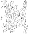
- the network 10 is configured as a back propagation network and comprises individual processing elements 12 configured into at least three layers 14, 16 and 18. Of these layers the layer 14 is termed the “input layer”, the layer 18 the “output layer”, and the intermediate layer 16 the “hidden layer”.
- the processing network 10 is organized such that the input layer 14 contains a set of at least one to i processing elements, the hidden layer 16 has a set of at least one to k processing elements, and the output layer 18 has a set of at least one toj processing elements therein.
- an operator would specify the values i, k and j.
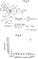
- FIG. 2 is a generalized representation of a processing element 12 used throughout the network 10.
- Each processing element 12 has an input port Pin and an output port Pout.
- the processing element is responsive to one or a plurality of excitation signal(s) I l though l m presented at the input port Pin and is operative to produce an activation signal Q out carried on a line Lout connected at the output port Pout.
- Each of the excitations I l though l m is connected to the input port Pin of the element 12 over a respective line L, though L m that has a predetermined respective connection weight W through W m .
- the activation signal Q out that is produced on the line Lout at the output port Pout of the processing element 12 is, as a general rule, a function of the input signal Q in applied at the input port Pin.
- the input signal Q in is the summation, over all of the input lines to the processing element, of the inner product of the strength of a given excitation signal I and the connection weight W of the line L carrying that signal to the processing element, scaled by the squashing function S for that processing element.
- the activation signal Q out at the output port Pout is functionally related to the input signal Q in where where T is the threshold of the processing element 12.
- the threshold T can be considered as an additional weight from an input line (m + 1) having a constant excitation signal of one (1), similar to the prior art.
- the squashing function S takes the form of the sigmoid function
- each of the processing elements 14-1 through 14-i in the input layer 14 is connected to at least one of a predetermined number i of network input signals on a respective input line 22.
- Each of the lines 22 may have a predetermined weight associated therewith, similar to the situation discussed above in the case of the generalized processing element. It should be understood that a given processing element in the input layer 14 may be connected to more than one of the input signals, if desired.
- Each of the processing elements in the input layer 14 is operative, in a manner similar to that described above for the generalized processing element, to produce a respective activation signal A1 [I] through A1 [i] at the output port thereof.
- the output port of each of the i processing elements in the input layer 14 is connected to at least one of the k processing elements 16-1 through 16-k in the intermediate layer 16 of processing elements by a respective line 24.
- the output port of each of the processing elements in the input layer 14 is connected to the input port of each of the processing elements in the intermediate layer 16.
- Each such interconnection line 24 has a connection weight W1[i,k] associated therewith.
- the processing elements in the intermediate layer 16 respond to the inputs applied thereto to produce an activation signal A2[k] at the output port thereof.
- the output port of each of the k processing elements in the intermediate layer 16 is connected to the input port of at least one of the j processing elements in the output layer 18 of processing elements on a line 26.
- the output port of each element in the intermediate layer 16 is connected to the input port of one of the processing elements in the output layer 18.
- the lines 26 each have a connection weight W2[k,j] associated therewith.
- the processing elements in the output layer 18 respond to the inputs thereto to produce an activation signal A3[i] at the output port thereof. These output signals are carried over respective output lines 28.
- a training set comprising an array containing from one to p sets of input signals is applied to the input lines 22 of the network 10.
- the error E to be minimized is the squared difference between the desired output V[j, p] and the actual output A3[j,p] when the input pattern p is presented to the network.
- the present invention revolves upon the recognition that the training of a back propagation network using the conventional training rule described above is closely analogous to systems which are governed by stiff differential equations. Such systems are characterized by time constants which vary greatly in magnitude. In the case of a back propagation network this corresponds to the fact that some weights reach a near steady state value very rapidly while others change only very slowly. Moreover, sometimes a weight will remain unchanged for a large number of iterations and then suddenly change to another quasi-steady state value. This is a common occurrence for variables in a stiff differential system. Finally, prior art solution schemes for neural networks involve heuristics for adjusting the values of the constants eta and alpha (from Equation (1)) to try to obtain rapid but stable convergence.
- the fundamental training concept of the back propagation network is to change the weights in accordance with the Generalized Delta Rule given by the method of steepest descent in such a way as to decrease the total squared error E.
- the training in accordance with the present invention is presumed to take place as a continuous time evolution of the weights W.
- the conventional discrete-step iterative scheme of Equation (1) is a fixed- time-step forward-Euler method for solving the underlying differential equations which is both inefficient and potentially unstable when applied to a system of stiff differential equations.
- Equations (6) and (7) relating the various layers of the network can be written as differential equations and
- Equations (6a) and (7a) are a set of coupled nonlinear ordinary differential equations for the continuous variables W1[i,k] and W2[k,j].
- the initial conditions are small random weights.
- This system of equations may be integrated numerically to solve the equations, such that, as time increases, the weights converge to steady state values corresponding to those giving a local minimum least-squares prediction error.
- the equations are numerically solved using the stiff integration package DGEARfrom the IMSL Library, sold by IMSL, Inc. Houston, Texas.
- the original version of the algorithm used in the package DGEAR is disclosed in Gear, C. W., Numerical Initial Value Problems in Ordinary Differential Equations, Prentice-Hall, Eng- lewood Cliffs, New Jersey (1971).
- the network 10 may be implemented in any of a variety of forms.
- the network may be formed as the interconnection of discrete analog components in the manner indicated in the Figures.
- the network may be formed as an integrated circuit in which the layers of processing elements and the interconnection lines between them are integrated onto a suitable substrate by any appropriate integration process (in Figure 1 the plane of the paper can be considered the substrate).
- the interconnection weights between the processing elements would preferably take the form of resistances in the connection lines.
- an optical (holographic) implementation can be used.
- the network is implemented using a programmed digital computer, either in the form of a mainframe (such as a CRAY X-MP), a mini computer (such as a Digital Equipment Corporation VAX) or in the form of one or more microcomputers or one or more boards having a microprocessor thereon.
- a mainframe such as a CRAY X-MP
- a mini computer such as a Digital Equipment Corporation VAX
- the network is implemented using a programmed digital computer, either in the form of a mainframe (such as a CRAY X-MP), a mini computer (such as a Digital Equipment Corporation VAX) or in the form of one or more microcomputers or one or more boards having a microprocessor thereon.
- the distributed parallel processing network can be implemented using one or more digital computer(s) having a traditional von Nuemann architecture (of whatever size or power desired) in which each processing element in each layer is configured during one or more instruction cycles of the computer(s) .
- connection weights W1, W2 for the back propagation network 10 are accomplished using a mathematical algorithm, such as the numerical integrator, the weights themselves are not mathematical in nature but represent physical connections between processing elements. Moreover, the network 10 as a whole is nonalgorithmic in nature. Stated alternatively, although a mathematical algorithm may be used to solve the underlying continuous differential equations and specify the values of the weights. the network having the processing elements connected by lines having those weights is not an algorithmic network.
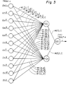
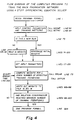
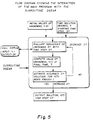
- Figure 3 is a schematic diagram of the parallel distributed processing network utilized in this example and configured to process information relative to a specific pattern recognition problem while Figures 4 and 5 are flow diagrams of a program used to determine the weights W1, W2 and the thresholds for the specific network shown in Figure 3.
- the specific details of the problem involved the classification of electronic parts as either being accepted or rejected.
- the parallel distributed processing network of the back propagation type as described heretofore is well suited for solving a wide variety of formulation, classification and pattern recognition problems.
- the network "learns" how to match a training set of inputs to outputs by adjusting the weights of the connections from the input processing elements to the intermediate processing elements and from the intermediate processing elements to the output processing elements.
- the training data set determines the number of input and output processing elements that are used.
- a pre-processing step is normally used, scaling the inputs and outputs individually in both the training data set and the prediction data set to lie in the range 0.1 to 0.9.
- the training data set is used to determine the values of the thresholds and weights of the interconnections in accordance with the present invention. (It is again noted that the thresholds may be treated as weights.)
- the prediction data set is used to verify and to validate the operation of a network having the weights as determined in accordance with the present invention. When scaling, usually a linear scaling is done, with 0.1 corresponding to the lowest value of a particular variable in the set and 0.9 corresponding to the highest.
- the data from eleven physical measurements of an electronic part was to be related to a visual inspector's classification into the categories REJECT [coded as 0.1] or ACCEPT [coded as 0.9].
- the training set consisted of forty two (42) samples, of which thirty six (36) samples were accepted and six (6) rejected.
- a user had only two choices to make in setting up the training of the network.
- an error tolerance of 0.01 was chosen, as shown in the listing of the input parameter file for training of the network (ELEC.PRM in the Appendix).
- the second user-adjustable parameter was the number of internal or hidden processing elements (k) used in the network.
- k the total number of adjustable weights and thresholds.
- n totai is small compared with the number of training samples, the network is "interpolative" in nature, and subtle variations in the input data cannot be mapped to output changes. If ntotal is large, the network approaches the "pattern recognition" mode in which it is memorizing each input pattern. If a few more internal elements are specified than needed, the network often tends to a solution in which several elements are either "on” or “off' for all the training patterns. These redundant elements can be removed from the network. If, on the other hand, too few hidden elements are specified, the network converges very slowly, and it tends to misclassify some of the members of the training set.
- the program input was read from two files, ELEC.PRM (on the input/output device identified in the listing as Fortran logical unit 15) and QSM.DAT (on the input/output device identified in the listing as Fortran logical unit 18).
- ELEC.PRM on the input/output device identified in the listing as Fortran logical unit 15
- QSM.DAT on the input/output device identified in the listing as Fortran logical unit 18
- TOLER RMS error tolerance
- NMAX maximum number of effective training presentations
- the set of training data is set forth in the file QSM.DAT.
- the eleven inputs, labeled TRINA 1 through TRINA 11, to correspond to the variable name used in the program, for each of the forty two training patterns are shown one per line in the listing of the file QSM.DAT.
- the forty two outputs TROUTA (also given the variable Y in the listing), have the values of 0.1 and 0.9 corresponding to REJECT and ACCEPT, respectively.
- the sets of input signals TRINA corresponds to the sets input signals INPUT(i) shown in Figure 1 and to the inputs I shown in connection with Figure 2.
- subroutine INCONT (lines 446 to 459) read the information stored in file ELEC.PRM from the input/output device identified in the listing as Fortran logical unit 15.
- Subroutine GETPAT (lines 460 to 482) read the training patterns in the file QSM.DAT from Fortran logical unit 18, storing them in variables named TRINA (eleven inputs per training pattern) and TROUTA (one output per training pattern).
- TRINA eleven inputs per training pattern
- TROUTA one output per training pattern
- lines 103 to 116 of the Appendix would read the file ELEC.W containing previously calculated weights and thresholds from the input/output device identified in the listing Fortran logical unit 29.
- the training was started from random initial conditions, which along with control parameters for the subroutine DGEAR are set in lines 117 to 159.
- Lines 160 to 205 in the main routine FORMUL were a loop in which the subroutine DGEAR was called repeatedly (lines 164-165), with increasing ending time TEND, which was initially one hundred.
- the main program loop (lines 160 to 205) was also stopped if either of the two above discussed convergence criteria were met: a root-mean-squared prediction error in the outputs less than TOLER, or all of the prediction errors less than three times tolerance (3 * TOLER). If convergence or NMAX was reached, program control was passed to line 206, and the final monitoring printout (lines 209 to 210) and writing of ELEC.W (lines 211 to 221) were done before the program stopped (line 223).
- the subroutine DIFFUN (lines 228 to 435) took as input the values Y (representing the weights W1 and W2 and the thresholds THETA1 and THETA2 of the network being trained) and computed the instantaneous time rate of change of these values.
- DY dY/dt.
- the thresholds were treated as weights.
- the Input values Y were stored in the appropriate weight and threshold variables, and temporary storage variables for the weight changes are initialized.
- the DO loop in lines 308 to 390 evaluated the gradient-descent weight changes given in Equations (6a) and (7a). These quantities were stored in the appropriate locations of the output vector DY in lines 397 to 417.
- the printout NEURAL.CPR shows the output for the example data set QSM.DAT (with explanatory material being added).
- the example had forty two training patterns and twenty seven adjustable weights and thresholds.
- the routine FORMUL converged to better than 0.01 RMS prediction error in a time of 25,600 effective training iterations.
- the FLOWTRACE specific to CRAY computer systems, shows how many times each routine was called.
- the training weights and thresholds obtained are given in the printout of the file ELEC.W. Because computers generate machine specific random number sequences. the details of the results shown in NEURAL.CPR and ELEC.W will not be the same on other computers.
- the final listing provided with this example is the routine PREDCT.FOR.
- This is a VAX Fortran program which implements a distributed parallel processing network trained in accordance with the present invention.
- the routine PREDCT.FOR utilized the prediction set of data to verify and validate that a distributed parallel processing network in which the values of the weights between the input layer and the intermediate layer and between the intermediate layer and the output layer were adjusted in accordance with the steady state solution sets of the differentials equations as given in Equations (6a) and (7a) would accurately result in the appropriate classification of electronic parts as either REJECT or ACCEPT.
- the network was implemented on a Digital Equipment Corporation VAX.
- the VAX operating in accordance with the routine PREDCT.FOR, read the files ELEC.PRM, QSM.DAT and ELEC.W. It thcn used the weights found as the steady state solutions of the stiff differential equations set forth in Equations (6a) and (7a) to predict the outputs for the prediction set of patterns in QSM.DAT.
- the file ELEC.OUT shows the result of this computation for the weights and thresholds given in the file ELEC.W.
- the uniform convergence of the RMS prediction error is Illustrated in the file NEURAL.CPR along with the rapid buildup of the computation step size being used.
- the network is learning at a rate hundreds of times faster than the traditional iteration scheme.
- Distributed parallel processing network methods such as those outlined here can be a useful complement to traditional statistical methods, particularly when the underlying interactions are complex and nonlinear.
- the network can accommodate a more complex (i.e., non- linear) relationship between inputs and outputs.
- the underlying principle of minimizing the least squares prediction error is the same, but the back propagation network is more general.
- the network is model-free, in contrast with nonlinear least squares fitting procedures, since no assumption is made about the inherent functional form relating inputs to outputs; the accuracy of the representation is limited only by the quality of the data, not by the adequacy of the model.
Landscapes
- Engineering & Computer Science (AREA)
- Theoretical Computer Science (AREA)
- Physics & Mathematics (AREA)
- Computing Systems (AREA)
- General Physics & Mathematics (AREA)
- Biomedical Technology (AREA)
- Biophysics (AREA)
- Computational Linguistics (AREA)
- Data Mining & Analysis (AREA)
- Evolutionary Computation (AREA)
- General Health & Medical Sciences (AREA)
- Molecular Biology (AREA)
- Life Sciences & Earth Sciences (AREA)
- General Engineering & Computer Science (AREA)
- Artificial Intelligence (AREA)
- Mathematical Physics (AREA)
- Software Systems (AREA)
- Health & Medical Sciences (AREA)
- Paper (AREA)
- Complex Calculations (AREA)
- Supply And Distribution Of Alternating Current (AREA)
- Image Analysis (AREA)
- Lift-Guide Devices, And Elevator Ropes And Cables (AREA)
- Electrical Discharge Machining, Electrochemical Machining, And Combined Machining (AREA)
- Data Exchanges In Wide-Area Networks (AREA)
- Multi Processors (AREA)
- Hardware Redundancy (AREA)
Claims (10)


Applications Claiming Priority (3)
| Application Number | Priority Date | Filing Date | Title |
|---|---|---|---|
| US07/285,534 US5046020A (en) | 1988-12-16 | 1988-12-16 | Distributed parallel processing network wherein the connection weights are generated using stiff differential equations |
| US285534 | 1988-12-16 | ||
| PCT/US1989/005546 WO1990007158A1 (en) | 1988-12-16 | 1989-12-13 | A distributed parallel processing network wherein the connection weights are generated using stiff differential equations |
Publications (3)
| Publication Number | Publication Date |
|---|---|
| EP0449994A1 EP0449994A1 (de) | 1991-10-09 |
| EP0449994A4 EP0449994A4 (en) | 1992-04-29 |
| EP0449994B1 true EP0449994B1 (de) | 1995-05-10 |
Family
ID=23094658
Family Applications (1)
| Application Number | Title | Priority Date | Filing Date |
|---|---|---|---|
| EP90905374A Expired - Lifetime EP0449994B1 (de) | 1988-12-16 | 1989-12-13 | Verteiltes parallelverarbeitungsnetzwerk, worin die verbindungsgewichte mit hilfe von starren differentialgleichungen erzeugt werden |
Country Status (10)
| Country | Link |
|---|---|
| US (1) | US5046020A (de) |
| EP (1) | EP0449994B1 (de) |
| JP (1) | JPH0760428B2 (de) |
| KR (1) | KR930004438B1 (de) |
| AT (1) | ATE122483T1 (de) |
| AU (1) | AU5411090A (de) |
| CA (1) | CA2005370A1 (de) |
| DE (1) | DE68922624T2 (de) |
| ES (1) | ES2073567T3 (de) |
| WO (1) | WO1990007158A1 (de) |
Families Citing this family (33)
| Publication number | Priority date | Publication date | Assignee | Title |
|---|---|---|---|---|
| JP2533942B2 (ja) * | 1989-03-13 | 1996-09-11 | 株式会社日立製作所 | 知識抽出方法およびプロセス運転支援システム |
| DE68927675T2 (de) * | 1989-08-23 | 1997-07-10 | Hitachi Ltd | Verfahren zur Richtigstellung von Netzwerkwichtungsfaktoren in einer mehrschichtigen Perceptronvorrichtung und eine solche Vorrichtung mit Mitteln zur Ausführung dieses Verfahrens |
| GB8929146D0 (en) * | 1989-12-22 | 1990-02-28 | British Telecomm | Neural networks |
| US5167006A (en) * | 1989-12-29 | 1992-11-24 | Ricoh Company, Ltd. | Neuron unit, neural network and signal processing method |
| US5581662A (en) * | 1989-12-29 | 1996-12-03 | Ricoh Company, Ltd. | Signal processing apparatus including plural aggregates |
| JPH03250243A (ja) * | 1990-02-27 | 1991-11-08 | Toshiba Corp | 神経回路網演算装置 |
| JP2763182B2 (ja) * | 1990-06-28 | 1998-06-11 | 株式会社東芝 | ニューラル・ネットワークの学習方法 |
| JP2540654B2 (ja) * | 1990-06-28 | 1996-10-09 | シャープ株式会社 | ニュ―ラルネットワ―クの学習装置 |
| GB2246895B (en) * | 1990-07-12 | 1994-03-30 | Mitsubishi Electric Corp | Neural network system |
| JPH04266153A (ja) * | 1991-02-20 | 1992-09-22 | Honda Motor Co Ltd | ニューラルネットワーク |
| US5331550A (en) * | 1991-03-05 | 1994-07-19 | E. I. Du Pont De Nemours And Company | Application of neural networks as an aid in medical diagnosis and general anomaly detection |
| US5157275A (en) * | 1991-03-22 | 1992-10-20 | Ricoh Corporation | Circuit employing logical gates for calculating activation function derivatives on stochastically-encoded signals |
| US5528729A (en) * | 1991-06-12 | 1996-06-18 | Ricoh Company, Ltd. | Neural network learning apparatus and learning method |
| JPH05128085A (ja) * | 1991-11-08 | 1993-05-25 | Toshiba Corp | システム制御の学習方法 |
| CA2081036C (en) * | 1991-12-19 | 1999-08-03 | Ahmed Hashem Abdelmonem | Method and apparatus for predicting transmission system errors and failures |
| WO1993019426A1 (en) * | 1992-03-25 | 1993-09-30 | Western Mining Corporation Limited | Method of detecting and mapping minerals and other geological phenomena utilizing airborne imaging spectrometers |
| EP0574937B1 (de) * | 1992-06-19 | 2000-08-16 | United Parcel Service Of America, Inc. | Verfahren und Vorrichtung zur Eingabeklassifizierung mit einem neuronalen Netzwerk |
| US5428710A (en) * | 1992-06-29 | 1995-06-27 | The United States Of America As Represented By The Administrator Of The National Aeronautics And Space Administration | Fast temporal neural learning using teacher forcing |
| JPH06274660A (ja) * | 1993-03-18 | 1994-09-30 | Hitachi Ltd | 認識又は診断方法 |
| US5598509A (en) * | 1992-08-28 | 1997-01-28 | Hitachi, Ltd. | Method of configuring a neural network and a diagnosis/recognition system using the same |
| US5288645A (en) * | 1992-09-04 | 1994-02-22 | Mtm Engineering, Inc. | Hydrogen evolution analyzer |
| US5742702A (en) * | 1992-10-01 | 1998-04-21 | Sony Corporation | Neural network for character recognition and verification |
| US5319722A (en) * | 1992-10-01 | 1994-06-07 | Sony Electronics, Inc. | Neural network for character recognition of rotated characters |
| US5930781A (en) * | 1992-10-27 | 1999-07-27 | The United States Of America As Represented By The Administrator Of The National Aeronautics And Space Administration | Neural network training by integration of adjoint systems of equations forward in time |
| US5517667A (en) * | 1993-06-14 | 1996-05-14 | Motorola, Inc. | Neural network that does not require repetitive training |
| US5920852A (en) * | 1996-04-30 | 1999-07-06 | Grannet Corporation | Large memory storage and retrieval (LAMSTAR) network |
| US7215811B2 (en) * | 2000-11-22 | 2007-05-08 | Osama Moselhi | Method and apparatus for the automated detection and classification of defects in sewer pipes |
| US20060031027A1 (en) * | 2004-08-03 | 2006-02-09 | Alman David H | Method and apparatus for predicting properties of a chemical mixture |
| TW200928793A (en) * | 2007-12-26 | 2009-07-01 | Ruei-Jau Chen | Algorithm method capable of enhancing accuracy and computation speed of the computation of corrected sums of products (CSP) of computing hardware |
| US8218904B2 (en) * | 2008-08-27 | 2012-07-10 | Lockheed Martin Corporation | Method and system for circular to horizontal transposition of an image |
| US10192016B2 (en) * | 2017-01-17 | 2019-01-29 | Xilinx, Inc. | Neural network based physical synthesis for circuit designs |
| US11922314B1 (en) * | 2018-11-30 | 2024-03-05 | Ansys, Inc. | Systems and methods for building dynamic reduced order physical models |
| AR118333A1 (es) | 2019-03-18 | 2021-09-29 | Evonik Operations Gmbh | Método para generar una composición para pinturas, barnices, tintas de impresión, resinas de molienda, concentrados de pigmentos u otros materiales de recubrimiento |
Family Cites Families (2)
| Publication number | Priority date | Publication date | Assignee | Title |
|---|---|---|---|---|
| US4773024A (en) * | 1986-06-03 | 1988-09-20 | Synaptics, Inc. | Brain emulation circuit with reduced confusion |
| WO1988007234A1 (en) * | 1987-03-12 | 1988-09-22 | Analog Intelligence Corporation | Back propagation system |
-
1988
- 1988-12-16 US US07/285,534 patent/US5046020A/en not_active Expired - Fee Related
-
1989
- 1989-12-13 AU AU54110/90A patent/AU5411090A/en not_active Abandoned
- 1989-12-13 JP JP2505832A patent/JPH0760428B2/ja not_active Expired - Lifetime
- 1989-12-13 WO PCT/US1989/005546 patent/WO1990007158A1/en not_active Ceased
- 1989-12-13 DE DE68922624T patent/DE68922624T2/de not_active Expired - Fee Related
- 1989-12-13 CA CA002005370A patent/CA2005370A1/en not_active Abandoned
- 1989-12-13 EP EP90905374A patent/EP0449994B1/de not_active Expired - Lifetime
- 1989-12-13 AT AT90905374T patent/ATE122483T1/de active
- 1989-12-13 ES ES90905374T patent/ES2073567T3/es not_active Expired - Lifetime
-
1990
- 1990-08-18 KR KR9071807A patent/KR930004438B1/ko not_active Expired - Fee Related
Also Published As
| Publication number | Publication date |
|---|---|
| EP0449994A1 (de) | 1991-10-09 |
| US5046020A (en) | 1991-09-03 |
| ATE122483T1 (de) | 1995-05-15 |
| KR930004438B1 (en) | 1993-05-27 |
| DE68922624T2 (de) | 1995-10-19 |
| EP0449994A4 (en) | 1992-04-29 |
| JPH04503274A (ja) | 1992-06-11 |
| KR910700501A (ko) | 1991-03-15 |
| ES2073567T3 (es) | 1995-08-16 |
| AU5411090A (en) | 1990-07-10 |
| DE68922624D1 (de) | 1995-06-14 |
| WO1990007158A1 (en) | 1990-06-28 |
| JPH0760428B2 (ja) | 1995-06-28 |
| CA2005370A1 (en) | 1990-06-16 |
Similar Documents
| Publication | Publication Date | Title |
|---|---|---|
| EP0449994B1 (de) | Verteiltes parallelverarbeitungsnetzwerk, worin die verbindungsgewichte mit hilfe von starren differentialgleichungen erzeugt werden | |
| EP0360674B1 (de) | Signalverarbeitungssystem und Lernverarbeitungssystem | |
| Pearlmutter | Gradient calculations for dynamic recurrent neural networks: A survey | |
| Atiya | Learning on a general network | |
| US5455890A (en) | Method for structuring an expert system utilizing one or more neural networks | |
| US6965885B2 (en) | Self-organizing feature map with improved performance by non-monotonic variation of the learning rate | |
| Sorsa et al. | Application of artificial neural networks in process fault diagnosis | |
| US5630020A (en) | Learning method and neural network structure | |
| Brown et al. | Neural networks for modeling and control | |
| Patrikar et al. | Control of dynamic systems using fuzzy logic and neural networks | |
| Neumerkel et al. | Modelling dynamic processes with clustered time-delay neurons | |
| Zweiri et al. | A new three-term backpropagation algorithm with convergence analysis | |
| Moody et al. | Neural network construction and rapid learning for system identification | |
| Scott et al. | Neural network process models based on linear model structures | |
| Howlett et al. | The Class-Distributed Neural Network | |
| Ku et al. | Diagonal recurrent neural network-based control: convergence and stability | |
| Murao et al. | Evolution of locally defined learning rules and their coordination in feedforward neural networks | |
| Bobrowski | Rules of forming receptive fields of formal neurons during unsupervised learning processes | |
| Arularasan et al. | An analysis of network parallelism of backpropagation neural networks on a transputer array | |
| Wu et al. | An enhanced neural network learning using a self-tuning fuzzy neuron controller | |
| Tzafestas et al. | An improved neural network for fuzzy reasoning implementation | |
| Pican et al. | How OWE architectures encode contextual effects in artificial neural networks | |
| Al-Akhras et al. | Multi-model neural network-based intelligent controller | |
| Amin et al. | Application of dynamic neural networks to approximation and control of nonlinear systems | |
| Shaw | Neurofuzzy Controllers |
Legal Events
| Date | Code | Title | Description |
|---|---|---|---|
| PUAI | Public reference made under article 153(3) epc to a published international application that has entered the european phase |
Free format text: ORIGINAL CODE: 0009012 |
|
| 17P | Request for examination filed |
Effective date: 19910711 |
|
| AK | Designated contracting states |
Kind code of ref document: A1 Designated state(s): AT BE CH DE ES FR GB IT LI LU NL SE |
|
| A4 | Supplementary search report drawn up and despatched |
Effective date: 19920310 |
|
| AK | Designated contracting states |
Kind code of ref document: A4 Designated state(s): AT BE CH DE ES FR GB IT LI LU NL SE |
|
| 17Q | First examination report despatched |
Effective date: 19940816 |
|
| GRAA | (expected) grant |
Free format text: ORIGINAL CODE: 0009210 |
|
| AK | Designated contracting states |
Kind code of ref document: B1 Designated state(s): AT BE CH DE ES FR GB IT LI LU NL SE |
|
| REF | Corresponds to: |
Ref document number: 122483 Country of ref document: AT Date of ref document: 19950515 Kind code of ref document: T |
|
| REF | Corresponds to: |
Ref document number: 68922624 Country of ref document: DE Date of ref document: 19950614 |
|
| ET | Fr: translation filed | ||
| ITF | It: translation for a ep patent filed | ||
| REG | Reference to a national code |
Ref country code: ES Ref legal event code: FG2A Ref document number: 2073567 Country of ref document: ES Kind code of ref document: T3 |
|
| PLBE | No opposition filed within time limit |
Free format text: ORIGINAL CODE: 0009261 |
|
| STAA | Information on the status of an ep patent application or granted ep patent |
Free format text: STATUS: NO OPPOSITION FILED WITHIN TIME LIMIT |
|
| 26N | No opposition filed | ||
| REG | Reference to a national code |
Ref country code: CH Ref legal event code: PUE Owner name: E.I. DU PONT DE NEMOURS & COMPANY TRANSFER- E.I. D |
|
| REG | Reference to a national code |
Ref country code: GB Ref legal event code: 732E |
|
| REG | Reference to a national code |
Ref country code: FR Ref legal event code: TP |
|
| PGFP | Annual fee paid to national office [announced via postgrant information from national office to epo] |
Ref country code: GB Payment date: 19961204 Year of fee payment: 8 |
|
| PGFP | Annual fee paid to national office [announced via postgrant information from national office to epo] |
Ref country code: FR Payment date: 19961211 Year of fee payment: 8 |
|
| PGFP | Annual fee paid to national office [announced via postgrant information from national office to epo] |
Ref country code: AT Payment date: 19961212 Year of fee payment: 8 |
|
| PGFP | Annual fee paid to national office [announced via postgrant information from national office to epo] |
Ref country code: SE Payment date: 19961218 Year of fee payment: 8 |
|
| PGFP | Annual fee paid to national office [announced via postgrant information from national office to epo] |
Ref country code: CH Payment date: 19961219 Year of fee payment: 8 |
|
| PGFP | Annual fee paid to national office [announced via postgrant information from national office to epo] |
Ref country code: DE Payment date: 19961223 Year of fee payment: 8 |
|
| PGFP | Annual fee paid to national office [announced via postgrant information from national office to epo] |
Ref country code: ES Payment date: 19961228 Year of fee payment: 8 |
|
| PGFP | Annual fee paid to national office [announced via postgrant information from national office to epo] |
Ref country code: NL Payment date: 19961231 Year of fee payment: 8 |
|
| PGFP | Annual fee paid to national office [announced via postgrant information from national office to epo] |
Ref country code: BE Payment date: 19970214 Year of fee payment: 8 |
|
| PGFP | Annual fee paid to national office [announced via postgrant information from national office to epo] |
Ref country code: LU Payment date: 19970407 Year of fee payment: 8 |
|
| NLS | Nl: assignments of ep-patents |
Owner name: STERLING DIAGNOSTIC IMAGING, INC. |
|
| PG25 | Lapsed in a contracting state [announced via postgrant information from national office to epo] |
Ref country code: LU Free format text: LAPSE BECAUSE OF NON-PAYMENT OF DUE FEES Effective date: 19971213 Ref country code: GB Free format text: LAPSE BECAUSE OF NON-PAYMENT OF DUE FEES Effective date: 19971213 Ref country code: AT Free format text: LAPSE BECAUSE OF NON-PAYMENT OF DUE FEES Effective date: 19971213 |
|
| PG25 | Lapsed in a contracting state [announced via postgrant information from national office to epo] |
Ref country code: SE Free format text: LAPSE BECAUSE OF NON-PAYMENT OF DUE FEES Effective date: 19971214 |
|
| PG25 | Lapsed in a contracting state [announced via postgrant information from national office to epo] |
Ref country code: LI Free format text: LAPSE BECAUSE OF NON-PAYMENT OF DUE FEES Effective date: 19971231 Ref country code: FR Free format text: THE PATENT HAS BEEN ANNULLED BY A DECISION OF A NATIONAL AUTHORITY Effective date: 19971231 Ref country code: CH Free format text: LAPSE BECAUSE OF NON-PAYMENT OF DUE FEES Effective date: 19971231 Ref country code: BE Free format text: LAPSE BECAUSE OF NON-PAYMENT OF DUE FEES Effective date: 19971231 |
|
| BERE | Be: lapsed |
Owner name: E.I. DU PONT DE NEMOURS AND CY Effective date: 19971231 |
|
| PG25 | Lapsed in a contracting state [announced via postgrant information from national office to epo] |
Ref country code: NL Free format text: LAPSE BECAUSE OF NON-PAYMENT OF DUE FEES Effective date: 19980701 |
|
| GBPC | Gb: european patent ceased through non-payment of renewal fee |
Effective date: 19971213 |
|
| REG | Reference to a national code |
Ref country code: CH Ref legal event code: PL |
|
| NLV4 | Nl: lapsed or anulled due to non-payment of the annual fee |
Effective date: 19980701 |
|
| PG25 | Lapsed in a contracting state [announced via postgrant information from national office to epo] |
Ref country code: DE Free format text: LAPSE BECAUSE OF NON-PAYMENT OF DUE FEES Effective date: 19980901 |
|
| EUG | Se: european patent has lapsed |
Ref document number: 90905374.6 |
|
| REG | Reference to a national code |
Ref country code: FR Ref legal event code: ST |
|
| PG25 | Lapsed in a contracting state [announced via postgrant information from national office to epo] |
Ref country code: ES Free format text: LAPSE BECAUSE OF NON-PAYMENT OF DUE FEES Effective date: 19981214 |
|
| REG | Reference to a national code |
Ref country code: ES Ref legal event code: FD2A Effective date: 19990114 |
|
| PG25 | Lapsed in a contracting state [announced via postgrant information from national office to epo] |
Ref country code: IT Free format text: LAPSE BECAUSE OF NON-PAYMENT OF DUE FEES;WARNING: LAPSES OF ITALIAN PATENTS WITH EFFECTIVE DATE BEFORE 2007 MAY HAVE OCCURRED AT ANY TIME BEFORE 2007. THE CORRECT EFFECTIVE DATE MAY BE DIFFERENT FROM THE ONE RECORDED. Effective date: 20051213 |