EP0450118A1 - Fusée de proximité pour mine - Google Patents
Fusée de proximité pour mine Download PDFInfo
- Publication number
- EP0450118A1 EP0450118A1 EP90106318A EP90106318A EP0450118A1 EP 0450118 A1 EP0450118 A1 EP 0450118A1 EP 90106318 A EP90106318 A EP 90106318A EP 90106318 A EP90106318 A EP 90106318A EP 0450118 A1 EP0450118 A1 EP 0450118A1
- Authority
- EP
- European Patent Office
- Prior art keywords
- mine
- ground
- microphones
- mines
- electrical signals
- Prior art date
- Legal status (The legal status is an assumption and is not a legal conclusion. Google has not performed a legal analysis and makes no representation as to the accuracy of the status listed.)
- Withdrawn
Links
- 239000003380 propellant Substances 0.000 claims abstract description 22
- 239000002360 explosive Substances 0.000 claims abstract description 18
- 239000000463 material Substances 0.000 claims abstract description 11
- 238000012545 processing Methods 0.000 claims abstract description 3
- 239000004020 conductor Substances 0.000 claims description 2
- 238000010586 diagram Methods 0.000 description 5
- 238000012986 modification Methods 0.000 description 3
- 230000004048 modification Effects 0.000 description 3
- 238000010276 construction Methods 0.000 description 2
- 238000012360 testing method Methods 0.000 description 2
- 238000013459 approach Methods 0.000 description 1
- 238000010304 firing Methods 0.000 description 1
- 230000009191 jumping Effects 0.000 description 1
- 230000000670 limiting effect Effects 0.000 description 1
- 238000000034 method Methods 0.000 description 1
- 230000005236 sound signal Effects 0.000 description 1
Images


Classifications
-
- F—MECHANICAL ENGINEERING; LIGHTING; HEATING; WEAPONS; BLASTING
- F42—AMMUNITION; BLASTING
- F42C—AMMUNITION FUZES; ARMING OR SAFETY MEANS THEREFOR
- F42C13/00—Proximity fuzes; Fuzes for remote detonation
- F42C13/06—Proximity fuzes; Fuzes for remote detonation operated by sound waves
-
- F—MECHANICAL ENGINEERING; LIGHTING; HEATING; WEAPONS; BLASTING
- F42—AMMUNITION; BLASTING
- F42C—AMMUNITION FUZES; ARMING OR SAFETY MEANS THEREFOR
- F42C11/00—Electric fuzes
- F42C11/001—Electric circuits for fuzes characterised by the ammunition class or type
- F42C11/007—Electric circuits for fuzes characterised by the ammunition class or type for land mines
Definitions
- the present invention relates to a proximity detector mine system for use against approaching targets.
- the invention is particularly applicable for use against helicopters, and is therefore described below with respect to this application.
- An object of the present invention is to provide a proximity detector mine system which is particularly, but not exclusively, applicable with respect to approaching helicopters.
- a proximity detector mine system comprising a a mine deployable on the ground and including a propellant device effective upon actuation to propel the mine above the ground, explosive material, a detonator for detonating the explosive material a predetermined time after the propellant has been actuated, sound sensing means comprising a plurality of directional microphones oriented in different directions producing electrical signals in response to the sounds sensed thereby, and a processor for processing the electrical signals and for actuating the propellant device in response to the electrical signals received from the sound sensing means.
- the propellant device for propelling the mine above the ground may be of a type presently used in "jumping mines" which, upon actuation, propel the mine a few meters above the ground before the explosive is detonated by the detonator. In the case of the present invention, however, the propellant device should propel the mine a distance of approximately fifty meters above the ground in order to make the explosive more effective against helicopters.
- a propellant device may be another explosive, or a jet-type device, effective upon actuation to propel the mine above the ground a distance of the order of fifty meters.
- the detonator is actuated for detonating the explosive material within the mine, thereby making the mine effective against low-flying helicopters.
- the processor includes recognition means for recognizing the sounds of a helicopter and for actuating the propellant device in response thereto.
- the sound sensing means comprises a plurality (e.g., four) directional microphones oriented at equal angular distances (e.g., 90 o ) with respect to each other.
- the processor actuates the propellant device when the sound from one microphone is substantially equal to that of the microphone oriented 180 o with respect thereto, or when the sum of the sounds from two adjacent microphones is substantially equal to that of the other two microphones.
- a proximity detector mine system comprising a plurality of such mines deployable on the ground, and a central processor including means for selectively disabling all the mines.
- a central processor including means for selectively disabling all the mines.
- the central processor also includes means for enabling the mines sequentially at predetermined time intervals, e.g., every two seconds.
- predetermined time intervals e.g., every two seconds.
- the mine illustrated in Figs. 1 and 2 comprises a casing, generally designated 2, housing explosive material 4 and an explosive detonator, diagrammatically illustrated by box ED, for detonating the explosive material.
- the mine further includes a propellant device, diagrammatically illustrated by box PD, which is effective, upon actuation, to propel the mine above the ground before the explosive material is detonated.
- propellant device PD which may be another explosive charge as mentioned above, should be effective to propel the mine a distance of about fifty meters above the ground in order to make the mine effective against helicopters.
- the mine illustrated in Figs. 1 and 2 further includes four directional microphones, as schematically indicated at Ma, Mb, Mc, Md, oriented 90 o with respect to each other.
- the mine further includes a processor unit PU which processes the electrical signals produced by the microphones Ma-Md and actuates the propellant device PD when the electrical signals received from the microphones indicate that a helicopter is at a predetermined location over the respective mine. Actuation of the propellant device PD propels the mine upwardly above the ground, and after a predetermined time interval the detonator ED is actuated to detonate the explosive material within the mine, as shown by the block diagram in Fig. 3.
- the processor unit PU within the mine is one programmed to perform the operations as illustrated by the flow diagram of Fig. 4.
- the program first checks to see whether the electrical signals produced by the four directional microphones Ma-Md are above a threshold, and if so, the program checks to determine whether these sounds are of the type produced by a helicopter.
- the sounds of a helicopter are quite distinctive, and therefore can be relatively easily identified by appropriate logic or correlation circuitry, either within the processor unit PU or externally thereof, enabling the pattern of electrical signals produced by the microphones to be compared with a reference pattern corresponding to the sounds produced by helicopters.
- the program in the processor unit PU then continuously checks to see whether the sound received from one microphone is substantially equal to that received from the microphone oriented 180 o with respect thereto, or whether the sum of the sounds from two adjacent microphones is substantially equal to that of the other two microphones. When any one of the above conditions has been found to be true, the program then tests to determine that the received sounds are above a predetermined threshold. When this is also true, it tests to determine when the sound signals tend to decrease, thus indicating the target is closest to the mine, and when this ocurs it actuates the propellant device PD.
- the detonator ED is actuated to detonate the explosive, thereby increasing the chances of destroying or damaging the incoming helicopters.
- the program illustrated in Fig. 4 permits the detonator to be actuated when the sound from one microphone is substantially equal to that of the microphone oriented 1800 with respect thereto, or when the sum of the sounds from two adjacent microphones is substantially equal to that of the other two microphones.
- These conditions better assure that the mine will not be detonated except by a helicopter approaching the mine from any one of the four directions D1-D4 in Fig. 1, and that the helicopter will be at a predetermined location over the mine before the mine is detonated.
- the foregoing arrangement thus not only better assures that the mine will not be actuated until a helicopter is at a predetermined location with respect to the mine, but also better prevents a counter-measure actuation of the mines by an enemy using a sound generator located at a distance and simulating the sounds of a helicopter.
- Fig. 5 illustrates a modification, wherein the four microphones Ma-Md are connected to the mine housing, therein designated 20, by electrical conductors 21-24, respectively, to enable the microphones to be located at predetermined distances from the mine.
- the construction and operation of the mine illustrated in Fig. 5 may be the same as described above with respect to Figs. 1-4.
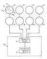
- Fig. 6 illustrates a further embodiment of the invention, wherein the system includes a plurality of mines, each indicated at 30, deployable on the ground, and a central processor, generally designated 32, connected to all the mines.
- Each of the mines 30 is constructed as described above with respect to Figs. 1-5, including four directional microphones Ma-Md, a propellant device PD, an explosive detonator ED, and a processor unit PU controlling each mine as described above.
- the processor unit PU of each mine is connected, either by a wire or by wireless, to the central processor 32.
- the central processor 32 includes a disabling circuit 34 for selectively disabling all the mines, e.g., when the respective area is to be overflown by friendly aircraft or to be occupied by friendly ground forces.
- the central processor 32 further includes a sequential enabling circuit 36, which sequentially enables each of the mines 30 at predetermined intervals, e.g., each two seconds. The purpose of the latter circuit is to prevent all the mines from being actuated at one time upon the approach of the first one of a plurlity of helicopters and thereby make the mine system more effective against a plurality of helicopters.
- the sequential firing arrangement also increases the possibility of destroying or damaging a single helicopter.
- the system could include a central microphone network controlling a plurality of mines. Also, there could be fewer than four microphones, e.g., one or two, or more microphones, e.g., five or six, all equally spaced in a circular array. Further, each mine could include a disabling circuit enabling a friendly aircraft or ground vehicle to disable the mine by a radio-transmitter disabling signal.
Landscapes
- Engineering & Computer Science (AREA)
- General Engineering & Computer Science (AREA)
- Measurement Of Velocity Or Position Using Acoustic Or Ultrasonic Waves (AREA)
Applications Claiming Priority (1)
| Application Number | Priority Date | Filing Date | Title |
|---|---|---|---|
| IL86525A IL86525A0 (en) | 1988-05-27 | 1988-05-27 | Promixity detector mine system |
Publications (1)
| Publication Number | Publication Date |
|---|---|
| EP0450118A1 true EP0450118A1 (fr) | 1991-10-09 |
Family
ID=11058878
Family Applications (1)
| Application Number | Title | Priority Date | Filing Date |
|---|---|---|---|
| EP90106318A Withdrawn EP0450118A1 (fr) | 1988-05-27 | 1990-04-03 | Fusée de proximité pour mine |
Country Status (3)
| Country | Link |
|---|---|
| US (1) | US4919051A (fr) |
| EP (1) | EP0450118A1 (fr) |
| IL (1) | IL86525A0 (fr) |
Cited By (2)
| Publication number | Priority date | Publication date | Assignee | Title |
|---|---|---|---|---|
| FR2682470A1 (fr) * | 1991-10-10 | 1993-04-16 | Diehl Gmbh & Co | Procede d'activation d'une mine. |
| WO1997013114A1 (fr) * | 1995-10-02 | 1997-04-10 | Stn Atlas Elektronik Gmbh | Mine terrestre |
Families Citing this family (9)
| Publication number | Priority date | Publication date | Assignee | Title |
|---|---|---|---|---|
| GB2227081B (en) * | 1988-12-24 | 1992-11-11 | Dynamit Nobel Ag | Mine |
| DE3927663C3 (de) * | 1989-08-22 | 1998-11-12 | Hirtenberger Ag | Vorrichtung für die Zielerkennung und Abschußauslösung für abzufeuernde Boden-Luftminen bei der Hubschrauberbekämpfung |
| DE4031089A1 (de) * | 1990-10-02 | 1992-04-09 | Diehl Gmbh & Co | Minensystem |
| FR2695718B1 (fr) * | 1992-09-15 | 1994-11-18 | Giat Ind Sa | Munition anti-aéronef et mine lançant une telle munition. |
| DE4330414A1 (de) * | 1993-09-08 | 1995-03-09 | Rheinmetall Gmbh | Mine |
| DE4439850C1 (de) * | 1994-11-08 | 1996-03-14 | Daimler Benz Aerospace Ag | Vorrichtung zur Lokalisierung von Artillerie- und Heckenschützenstellungen |
| SE520209C2 (sv) * | 2001-10-12 | 2003-06-10 | Foersvarets Materielverk | Handgranat innefattande anordning för att resa handgranaten från liggande till stående läge samt medel för att sända upp verkansdelen i luften innan brisad |
| US6606951B1 (en) * | 2002-11-07 | 2003-08-19 | The United States Of America As Represented By The Secretary Of The Army | Bounding anti-tank/anti-vehicle weapon |
| US9080842B2 (en) * | 2011-03-23 | 2015-07-14 | Lennie Mitchell | Human identification detection system |
Citations (5)
| Publication number | Priority date | Publication date | Assignee | Title |
|---|---|---|---|---|
| DE1516645A1 (de) * | 1965-02-15 | 1969-06-26 | Gen Dynamics Corp | System zur akustischen Signalanzeige |
| US3618013A (en) * | 1970-01-30 | 1971-11-02 | Krupp Gmbh | Transducer for determining the angle of incidence of sound waves |
| FR2265103A1 (fr) * | 1974-03-21 | 1975-10-17 | Krupp Gmbh | |
| DE3326748A1 (de) * | 1983-07-25 | 1985-02-07 | Fried. Krupp Gmbh, 4300 Essen | Mine |
| FR2622964A1 (fr) * | 1987-11-06 | 1989-05-12 | France Etat Armement | Procede et dispositif de mise en oeuvre d'un systeme de defense de zone contre la penetration de vehicules |
Family Cites Families (4)
| Publication number | Priority date | Publication date | Assignee | Title |
|---|---|---|---|---|
| US2341351A (en) * | 1941-05-15 | 1944-02-08 | Barkley Joseph Amos | Aerial mine |
| US3754508A (en) * | 1971-04-05 | 1973-08-28 | Avco Corp | Sensor employing a resistance variation detecting system |
| US3838642A (en) * | 1972-11-15 | 1974-10-01 | Us Navy | Pop-up antihelo mine |
| US4408533A (en) * | 1981-07-27 | 1983-10-11 | The United States Of America As Represented By The Secretary Of The Air Force | Acoustic amplitude-threshold target ranging system |
-
1988
- 1988-05-27 IL IL86525A patent/IL86525A0/xx unknown
-
1989
- 1989-05-26 US US07/357,936 patent/US4919051A/en not_active Expired - Fee Related
-
1990
- 1990-04-03 EP EP90106318A patent/EP0450118A1/fr not_active Withdrawn
Patent Citations (5)
| Publication number | Priority date | Publication date | Assignee | Title |
|---|---|---|---|---|
| DE1516645A1 (de) * | 1965-02-15 | 1969-06-26 | Gen Dynamics Corp | System zur akustischen Signalanzeige |
| US3618013A (en) * | 1970-01-30 | 1971-11-02 | Krupp Gmbh | Transducer for determining the angle of incidence of sound waves |
| FR2265103A1 (fr) * | 1974-03-21 | 1975-10-17 | Krupp Gmbh | |
| DE3326748A1 (de) * | 1983-07-25 | 1985-02-07 | Fried. Krupp Gmbh, 4300 Essen | Mine |
| FR2622964A1 (fr) * | 1987-11-06 | 1989-05-12 | France Etat Armement | Procede et dispositif de mise en oeuvre d'un systeme de defense de zone contre la penetration de vehicules |
Cited By (3)
| Publication number | Priority date | Publication date | Assignee | Title |
|---|---|---|---|---|
| FR2682470A1 (fr) * | 1991-10-10 | 1993-04-16 | Diehl Gmbh & Co | Procede d'activation d'une mine. |
| US5371502A (en) * | 1991-10-10 | 1994-12-06 | Diehl Gmbh & Co. | Method for the activation of a mine |
| WO1997013114A1 (fr) * | 1995-10-02 | 1997-04-10 | Stn Atlas Elektronik Gmbh | Mine terrestre |
Also Published As
| Publication number | Publication date |
|---|---|
| US4919051A (en) | 1990-04-24 |
| IL86525A0 (en) | 1988-11-15 |
Similar Documents
| Publication | Publication Date | Title |
|---|---|---|
| US4919051A (en) | Proximity detector mine system | |
| US4658727A (en) | Selectable initiation-point fragment warhead | |
| US4848239A (en) | Antiballistic missile fuze | |
| US4712479A (en) | Mine with alarm and triggering sensors | |
| US4662281A (en) | Low velocity disc pattern fragment warhead | |
| JP7146855B2 (ja) | 魚雷防御システム | |
| JP7499914B2 (ja) | 魚雷防御システム | |
| US4823701A (en) | Multi-point warhead initiation system | |
| US3811379A (en) | Encapsulated torpedo mine weapon system | |
| GB2057733A (en) | Transmitting information to explosive etc. devices | |
| EP0066168B1 (fr) | Détecteur de proximité | |
| US4975888A (en) | Mine neutralization system | |
| US6247408B1 (en) | System for sympathetic detonation of explosives | |
| US4991508A (en) | Electric field enabled proximity fuzing system | |
| US3763780A (en) | Mine-actuating system using one-shot mv timing circuit and timed mv feedback inhibitor | |
| US4739709A (en) | Lightweight detonation wave barrier | |
| EP0281722A1 (fr) | Système pour l'utilisation sous-marine des explosifs | |
| GB2211371A (en) | Position warning system | |
| US5147977A (en) | Device for the detection of objects and the release of firing for ground-to-air mines to be fired in the helicopter combat | |
| JP7175940B2 (ja) | 魚雷防御システム | |
| US6065403A (en) | Ignition device | |
| JP2021085653A (ja) | 魚雷防御システム | |
| JP6816343B1 (ja) | 魚雷防御システム | |
| RU2824870C1 (ru) | Неконтактный оптический взрыватель мины | |
| US4776273A (en) | Fuze arrangement for missiles |
Legal Events
| Date | Code | Title | Description |
|---|---|---|---|
| PUAI | Public reference made under article 153(3) epc to a published international application that has entered the european phase |
Free format text: ORIGINAL CODE: 0009012 |
|
| AK | Designated contracting states |
Kind code of ref document: A1 Designated state(s): AT BE CH DE DK ES FR GB GR IT LI NL SE |
|
| STAA | Information on the status of an ep patent application or granted ep patent |
Free format text: STATUS: THE APPLICATION IS DEEMED TO BE WITHDRAWN |
|
| 18D | Application deemed to be withdrawn |
Effective date: 19920410 |