EP0450152B1 - Procédé et dispositif destinés à l'imagerie tomographique à l'aide d'un balayage hélicoidal - Google Patents
Procédé et dispositif destinés à l'imagerie tomographique à l'aide d'un balayage hélicoidal Download PDFInfo
- Publication number
- EP0450152B1 EP0450152B1 EP90121417A EP90121417A EP0450152B1 EP 0450152 B1 EP0450152 B1 EP 0450152B1 EP 90121417 A EP90121417 A EP 90121417A EP 90121417 A EP90121417 A EP 90121417A EP 0450152 B1 EP0450152 B1 EP 0450152B1
- Authority
- EP
- European Patent Office
- Prior art keywords
- projection data
- slice
- point
- interpolation
- ray
- Prior art date
- Legal status (The legal status is an assumption and is not a legal conclusion. Google has not performed a legal analysis and makes no representation as to the accuracy of the status listed.)
- Expired - Lifetime
Links
Images


Classifications
-
- A—HUMAN NECESSITIES
- A61—MEDICAL OR VETERINARY SCIENCE; HYGIENE
- A61B—DIAGNOSIS; SURGERY; IDENTIFICATION
- A61B6/00—Apparatus or devices for radiation diagnosis; Apparatus or devices for radiation diagnosis combined with radiation therapy equipment
- A61B6/02—Arrangements for diagnosis sequentially in different planes; Stereoscopic radiation diagnosis
- A61B6/03—Computed tomography [CT]
- A61B6/032—Transmission computed tomography [CT]
-
- A—HUMAN NECESSITIES
- A61—MEDICAL OR VETERINARY SCIENCE; HYGIENE
- A61B—DIAGNOSIS; SURGERY; IDENTIFICATION
- A61B6/00—Apparatus or devices for radiation diagnosis; Apparatus or devices for radiation diagnosis combined with radiation therapy equipment
- A61B6/02—Arrangements for diagnosis sequentially in different planes; Stereoscopic radiation diagnosis
- A61B6/027—Arrangements for diagnosis sequentially in different planes; Stereoscopic radiation diagnosis characterised by the use of a particular data acquisition trajectory, e.g. helical or spiral
-
- G—PHYSICS
- G06—COMPUTING OR CALCULATING; COUNTING
- G06T—IMAGE DATA PROCESSING OR GENERATION, IN GENERAL
- G06T12/00—Tomographic reconstruction from projections
- G06T12/10—Image preprocessing, e.g. calibration, positioning of sources or scatter correction
Definitions
- the present invention relates to an X-ray CT (computerized tomographic) imaging apparatus and method according to the pre-characterizing part of claim 1 and claim 5, respectively. More particularly, the present invention is directed to a method and an apparatus for interpolating projection data acquired during a helical scanning operation by using projection data produced by opposite X-ray beams.
- a so-termed "3rd generation type X-ray CT imaging apparatus” is well known in the medical electronic field.
- the typical X-ray CT imaging system of the 3rd generation will now be summarized.
- an object "M” under medical examination such as a patient is fixedly mounted on a couch 2, and also both an X-ray tube 3 and an X-ray detector 4 are integrally rotated around the object M sandwiching this object M by them, an X-ray beam "XB" generated from the X-ray tube 3 is projected to the object "M" in order to acquire X-ray projection data over 360 degrees around the object M.
- a predetermined calculation/processing operation is executed so as to reconstruct an image, i.e., a computerized tomographic image (slice image) of the object "M" along the X-ray projection plane.
- Fig. 1C schematically illustrates an idea of this slice image. Accordingly, the X-ray projection data having the slice width corresponding to the projection width of the X-ray beam have been acquired over 0 degree to 360 degrees and the image reconstruction is carried out to obtain such a slice image.
- the projection data are acquired in the range of 360 degrees.
- the scanning operation must be interrupted and the object must be translated along the longitudinal direction of the couch 2 until a subsequent slice-obtaining position after the above-described scanning operation has been reached with respect to the previous slice-obtaining position. Then, a series of such scanning operations is restarted at this subsequent slice-obtaining position. Subsequently, the scanning operations must be similarly carried out with respect to the succeeding slice-obtaining positions.
- projection data on arbitrary slice positions are interpolated based upon the actually acquired projection data and thereafter both the interpolated projection data and the actually acquired projection data are processed for an image reconstruction purpose in the above-described conventional helical scanning system.
- Fig. 2D is a representation for explaining a principle of the interpolation method employed in the conventional helical scanning system (EP-A-0 383 232, published 22.08.90.) Under condition that the X-ray tube trail is varied in a sinusoidal form during the helical scanning operation, a region for obtaining a single slice corresponding to an arbitrary rotation (360 degrees) around the object under medical examination is set as "a major data acquisition region”.
- a center position of this 360-degree data acquisition region is a slice center position "SC”
- the projection data can be actually acquired only on a point "P”, which the X-ray tube trail has intersected, along a center line of this slice center "SC”
- the projection data cannot be actually acquired from any points along this center line, other than this point "P”.
- projection data of, for instance, a point "C 1 " located at an arbitrary position on this center line of the slice center "SC” is required, this projection data cannot be actually acquired but may be calculated by interpolating both actually acquired projection data on a point "A 1 " and also another point "B 1 ".
- This point "A 1 " is positioned at the nearest distance with respect to this point "C 1 " and the point “B 1 " is positioned far from this point “C 1 " but in the same rotation phase with these points C 1 and A 1 .
- This interpolation is carried out by utilizing the known linear interpolation method, and distances between this point C 1 and any points at the same rotation phase are used as weight coefficients for this linear interpolation.
- both the actually-acquired projection data at a point "A 2 " which is located at the shortest distance from this point C 2 in the same rotation phase, and also the other actually-acquired projection data at a point "B 2 " located opposite to this point "A 2 " in the same rotation phase are employed for the linear interpolation calculation. Since such a data interpolation processing operation is carried out in a similar manner as the above-described method and therefore the interpolated projection data at zero degree is coincident with that at 360 degrees within the 360°-X-ray beam projection range, the above-described occurence of an artifact may be reduced.
- both data acquisition regions "La" and “Lb” for interpolation are necessarily required within each 180-degree range at maximum with respect to the major data acquisition region "L” of 360 degrees. Accordingly, the above-described conventional linear interpolation calculation is performed by utilizing the actually acquired projection data obtained from the data acquisition region of 720 degrees in total.
- the thickness of the calculated effective slice necessarily becomes thick, because the desirable projection data on an arbitrary point along the center line of the slice center "SC" is calculated by linear-interpolating the projection data actually acquired at two points which are located in the same rotation phase with the arbitrary point and within two date acquisition regions with respect to the major data acquisition region involving this slice center "SC".
- the present invention has been made in an attempt to solve the above-described problems on the helical scanning type X-ray CT imaging system, and therefore has an object to provide an X-ray CT imaging apparatus capable of improving the interpolation precision of the helical scanning image data and also an improved image data interpolating method in the helical scanning system.
- an X-ray CT imaging apparatus (100), according to the present invention, comprises the features of claim 1.
- a method for reconstructing tomographic images of multi-planar slices of an object under medical examination in an X-ray computerized tomographic imaging apparatus (100), according to the present invention, comprises the steps indicated in claim 5.
- a helical scanning type X-ray CT (computerized tomographic) imaging apparatus 100 will be described.
- a gantry 1 is provided with a dome 6 having a function to guard an object "M" under medical examination, e.g., a patient.
- an X-ray tube 3 is positioned opposite to an X-ray detector 4 with sandwiching the object "M".
- the X-ray tube 3 is electrically operated under control of a high voltage generator 7, and also is rotatably controlled around the dome 6 under control of an X-ray tube drive controller 5.
- the X-ray detector 4 comprises a plurality of single detectors that are positioned in an array form, and detect X-rays which have been generated from the X-ray tube 3 and penetrated through the object "M".
- the couch 2 is designed to be continuously translated along a longitudinal direction "Z" of the object "M” under medical examination under control of an couch drive controller 8.
- a data acquisition unit 9 for acquiring actual projection data detected by the X-ray detector 4 is connected to the X-ray detector 4.
- An interpolation calculating unit 10 is connected to this data acquisition unit 9 so as to perform an interpolation calculation for desirable (slice) projection data based on projection data produced by opposite X-ray beams (this will be discussed more in detail) according to the present invention, by utilizing the actually-acquired projection data from the data acquisition unit 9.
- An image reconstructing unit 11 is connected to this interpolation calculation unit 10 in order to execute an image reconstruction process based on the interpolated projection data sent from the interpolation calculation unit 10.
- a display unit 12 is connected to this image reconstructing unit 11, so that tomographic images of the object "M" under medical examination are displayed thereon in response to the image reconstruction data derived from the image reconstruction unit 11. Furthermore, a system controller 13 is employed in order to control all of the above-described circuit arrangements.
- This system controller 13 is mainly constructed of a central processing unit (CPU) (not shown in detail).
- the interpolation calculation unit 10 performs the below-mentioned interpolation calculation for the helical-scanned projection data under control of the system controller 13.
- Fig. 4 illustrates a principal idea of a method for interpolating projection data acquired during the full helical scanning operation, in accordance with the present invention.
- a region for obtaining a single slice, corresponding to 360° of an arbitrary one rotation of the X-ray tube 3 around the object "M" under examination is set as a major data acquisition region "L”
- two data acquisition regions "L f1 " and "L f2 " for interpolation are set to both sides of the major data acquisition region "L", as viewed in Fig. 4.
- the maximum range of each data acquisition region "L f1 ", "L f2 " for interpolation is selected to be one fan angle of the X-ray beam. Generally, the typical fan angle is designed from 35° to 70°.
- the interpolation is similarly performed by utilizing both the actually-acquired projection data at a point "E 2 " which is located nearest this slice point "C 2 " and at the same rotation phase with this slice point "C 2 " during the helical scanning, and also the other actually-acquired projection data at a point "D 2 " (so-called “opposite-beam projection data") positioned opposite to the point "E 2 " as a center of the slice center (SC).
- Such an interpolation calculation is executed by utilizing both the actually-acquired projection data and opposite-beam projection data with respect to all projection angles in the CT imaging apparatus according to the first preferred embodiment shown in Fig. 3.
- Fig. 5 schematically represents a definition of projection data obtained by an opposite X-ray fan beam.
- the X-ray detector (not shown) is positioned so as to receive the X-ray fan beam emitted from the X-ray tube 3 and penetrated through the object under medical examination (not shown either), it may be recognized that there are plural X-ray beam channels between the X-ray tube 3 and the detector, the quantity of which corresponds to the total element number of the X-ray detector.
- Fig. 6 there is shown a calculation sample using the opposite beam relationship according to the present invention.
- this angle “ ⁇ ” is a rotation angle of the point "B” with reference to the point "A”, and this rotation angle of the point “B” indicates a position of a fan-beam source (X-ray tube) involving an X-ray beam positioned opposite to an X-ray beam for a specific channel of the point "A".
- Projection data No. ; No. ⁇ P ⁇ 1/2 + (n-2 No. ⁇ )/2 x ⁇ /360 ⁇
- n is a channel number
- P denotes a total number of projection data within one rotation
- No. ⁇ is equal to P x ⁇ /360 .
- a slice position of a tomographic image to be reconstructed by the helical scanning operation is set. Thereafter, a search is performed for X-ray beams positioned opposite with respect to the slice position as to each channel at the overall projection position on the slice position.
- the linear interpolation is carried out by employing the respective projection data produced by the mutually opposite X-ray beams which have been obtained for the respective channels, as explained above, so that desirable slice projection data at the slice position "A" can be obtained. Furthermore, other different projection data are similarly obtained, whereby all of the projection data at the slice positions may be interpolated.
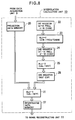
- FIG. 8 there is shown an internal arrangement of the interpolation calculation unit 10 represented in Fig. 3. It should be noted that for the sake of simplicity, no indication is made of the system controller 13 for controlling all of these internal arrangements.
- the interpolation calculation unit 10 shown in Fig. 8 includes a projection data memory 20 for receiving the actually-acquired projection data from the data acquisition unit 9 represented in Fig. 3, and for storing these projection data therein. These actually-acquired projection data stored in this memory 20 will be furnished to a first arithmetic and logic unit (ALU-1) 21 for the purpose of linear interpolation calculation.
- the interpolation calculation unit 10 further includes a first register 22 into which both a projection number (e.g., n-th projection number) and a channel number (e.g..).
- n-th channel have been stored in order to designate slice projection data to be interpolated; a second ALU 23 for checking whether or not opposite-beam projection data is present at an opposite side with respect to a slice center (plane) and also for obtaining both opposite-beam projection data (e.g., m'-th projection data) and a channel number thereof (e.g., n'-th channel number); and also a second register 24 for storing both the opposite-beam projection data and channel number thereof obtained by the second ALU 23.
- the interpolation calculation unit 10 further includes a third ALU 25 for calculating weight coefficients based upon the opposite-beam projection data and channel number thereof; and a third register 26 for storing the weight coefficients calculated by the second ALU 25.
- the calculated weight coefficients are supplied to the above-described first ALU 21 so as to perform the linear interpolation calculation with respect to the designated slice projection data, while utilizing the actually-acquired projection data stored in the projection data memory 20 and also the opposite-beam projection data based on the weight coefficients. Then, the interpolated-projection data is stored in an interpolated data memory 27 employed in this interpolation calculation unit 10.
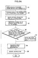
- the actually-acquired projection data is stored into the projection data memory 20 at a first step S1.
- the data to be interpolated i.e., slice projection data
- the opposite-beam projection data e.g., m'-th projection number
- the channel number e.g., n'-th channel number
- 360° data of the projection data to be interpolated e.g., m-th projection data
- an interpolation calculation is executed for the projection data to be interpolated by utilizing the calculated weight coefficients at a step 8.
- a similar projection data designation and interpolation calculation is carried out for the remaining projection data present on the slice center from the step S2 until the step S8.
- Fig. 9A is an illustration for explaining why the above-described checking step S5 shown in the above flowchart is required.
- the opposite-beam projection data is obtained with respect to a specific channel of the m-th projection data and a check must be done whether or not this opposite-beam projection data is located at an opposite side with respect to the side where the m-th projection data is present. That is, one opposite-beam projection data indicated by a symbol "o" is located at the opposite side as a center of the slice center. Conversely, another opposite-beam projection data indicated by a symbol " ⁇ " is located at the same side where the m-th projection data is present.
- slice projection data corresponding to an arbitrary rotation phase on an arbitrary slice plane may be interpolated by employing the so-called "opposite-beam projection data" and such a data interpolation may be realized by setting the narrow data regions L f1 and L f2 for interpolation purposes.
- a thickness of an effective slice image may be considerably reduced, as compared with that of the conventional interpolation method. Consequently, since the actually-acquired projection data obtained from a position which is relatively short from the slice plane may be utilized for this interpolation calculation, namely this interpolated projection data substantially becomes true projection data, precision of the interpolation calculation may be improved.
- a range of the major data acquisition region "L" was selected to be 360°.
- the present invention is not limited to such a full-helical scanning method, but may be a half-helical scanning method.
- slice projection data interpolation methods are performed by utilizing two projection data, i.e., actually-acquired projection data of one point on the slice plane and also opposite-beam projection data of the other point thereon, a high-order interpolation method (e.g., Lagrange's interpolation) with employment of projection data of more than two points on the same slice plane may be utilizied in the present invention.
- a high-order interpolation method e.g., Lagrange's interpolation
- the above-described preferred embodiments are realized in the 3rd generation type X-ray CT imaging system.
- the present invention may be apparently realized also in the 4th generation type X-ray CT imaging system.
Landscapes
- Health & Medical Sciences (AREA)
- Life Sciences & Earth Sciences (AREA)
- Engineering & Computer Science (AREA)
- Medical Informatics (AREA)
- Physics & Mathematics (AREA)
- Heart & Thoracic Surgery (AREA)
- Biomedical Technology (AREA)
- Biophysics (AREA)
- High Energy & Nuclear Physics (AREA)
- Theoretical Computer Science (AREA)
- Nuclear Medicine, Radiotherapy & Molecular Imaging (AREA)
- Optics & Photonics (AREA)
- Pathology (AREA)
- Radiology & Medical Imaging (AREA)
- Veterinary Medicine (AREA)
- Public Health (AREA)
- Molecular Biology (AREA)
- Surgery (AREA)
- Animal Behavior & Ethology (AREA)
- General Health & Medical Sciences (AREA)
- General Physics & Mathematics (AREA)
- Pulmonology (AREA)
- Apparatus For Radiation Diagnosis (AREA)
Claims (7)
- Appareil (100) d'imagerie de rayons X par tomographie informatisée, permettant de reconstruire des images tomographiques de coupes formées dans plusieurs plans d'un objet soumis à un examen médical, comprenant :un moyen (2) formant un lit de table et destiné à soutenir le sujet (M) soumis à l'examen médical;un moyen (8) de commande d'entraînement de lit de table, servant à commander le transport continu du moyen (2) formant un lit de table suivant l'axe longitudinal du sujet (M);une source (3) de faisceau de rayons X servant à émettre un faisceau de rayons X en forme d'éventail en direction des coupes formées dans plusieurs plans du sujet (M);un moyen détecteur (4) servant à détecter le faisceau de rayons X en forme d'éventail qui a pénétré dans les coupes du sujet (M) de manière à produire des données de projection représentatives d'intensités de profils du faisceau de rayons X en forme d'éventail;un moyen (1) servant à monter à la fois la source (3) de faisceau de rayons X et le moyen détecteur (4) de manière que la source (3) de faisceau de rayons X soit continûment positionnée à l'opposé du moyen détecteur (4) par rapport à la coupe du sujet (M), pendant la détection du faisceau de rayonnement en forme d'éventail, et à réaliser un déplacement relatif entre la source de faisceau de rayons X (3) et le sujet (M) dans un plan qui est perpendiculaire à l'axe longitudinal du sujet (M), si bien qu'une analyse en hélice entourant le sujet (M) est réalisée par le transport continu du moyen (2) formant un lit de table et le mouvement relatif existant entre eux;un moyen d'acquisition de données servant à acquérir des données de projection obtenues par l'intermédiaire de la rotation d'un portique;un moyen (10) de calcul d'interpolation permettant d'obtenir des données de projection de coupe au niveau d'un point d'une coupe prédéterminée (C1:C2) sur le plan d'une coupe (SC) sur la base de données provenant d'une région principale d'acquisition de données (L ; LH) et de deux régions d'acquisition de données relatives à l'interpolation (Lf1, Lf2 ; LH1, LH2), etun moyen (11) permettant de reconstruire une image tomographique du sujet,caractérisé en ce que:ledit moyen (10) de calcul d'interpolation obtient les données de projection de coupe en un point prédéterminé de la coupe (C1:C2) en effectuant un calcul d'interpolation sur la base d'au moins une paire de données formées d'une première donnée de projection réellement acquise en un premier point (D1:E2), qui est placé le plus près du point de la coupe (C1:C2) et possède la même relation de phase de rotation avec le point de la coupe (C1:C2) pendant l'analyse en hélice, et d'une deuxième donnée de projection réellement acquise en un deuxième point (E1:D2) placé à l'opposé du premier point (D1:E2), faisant fonction de centre du plan de la coupe (SC) ; chaque région d'acquisition de données relative à l'interpolation (Lf1, Lf2 ; LH1, LH2) correspondant à un angle inférieur à 180°.
- Appareil (100) d'imagerie de rayons X par tomographie informatisée selon la revendication 1, où ledit moyen (10) de calcul d'interpolation exécute le procédé d'interpolation linéaire en s'appuyant sur ladite paire de données de projection réellement acquises.
- Appareil (100) d'imagerie de rayons X par tomographie informatisée selon la revendication 1, où ledit moyen (10) de calcul d'interpolation exécute le procédé d'interpolation de Lagrange en s'appuyant sur au moins deux paires différentes de données de projection réellement acquises.
- Appareil (100) d'imagerie de rayons X par tomographie informatisée selon la revendication 1, où ledit moyen (10) de calcul d'interpolation comporte :un moyen (22) servant à désigner lesdites données de projection de coupe ;un moyen (23:24) servant à obtenir la deuxième donnée de projection réellement acquise au deuxième point (E1:D2) placé à l'opposé du premier point (D1:E2), faisant fonction du centre du plan de la coupe (SC) sur la base desdites données de projection de coupe désignées ;un moyen (25) servant à calculer des coefficients de pondération pour ladite paire formée desdites première et deuxième données de projection réellement acquises au premier point (D1:E2) et au deuxième point (E1:D2) sur la base de la relation de position existant entre lesdits premier et deuxième points par rapport audit plan de la coupe (SC);un moyen (21) permettant d'effectuer le calcul d'interpolation en utilisant à la fois lesdites première et deuxième données de projection réellement acquises aux premier et deuxième points et aussi leurs coefficients de pondération calculés.
- Procédé de reconstruction d'images tomographiques de coupes formées dans plusieurs plans d'un sujet soumis à un examen médical dans un appareil (100) d'imagerie de rayons X par tomographie informatisée, comprenant les opérations suivantes :irradier le sujet (M) soumis à l'examen médical au moyen d'un faisceau de rayons X en forme d'éventail, tout en déplaçant de façon continue l'objet (M) sur son axe longitudinal et en faisant relativement tourner une source (3) de rayonnement de rayons X et un détecteur (4) servant à détecter le faisceau de rayons X en forme d'éventail qui a pénétré à travers le sujet de façon à produire des données de projection représentatives d'intensités de profils du faisceau de rayons X en forme d'éventail, de sorte qu'une analyse en hélice autour du sujet (M) est réalisée par le transport continu du sujet (M);exécuter un calcul d'interpolation de façon à obtenir des données de projection de coupe en une coupe prédéterminée (C1:C2) sur un plan de la coupe (SC) sur la base de données venant d'une région principale d'acquisition de données (L ; LH) et de deux régions d'acquisition de données relatives à l'interpolation (Lf1, Lf2 ; LH1, LH2), etreconstruire une image tomographique du sujet à partir des données,caractérisé en ce que ladite opération d'exécution comprend l'opération suivante :utiliser au moins une paire de données formée d'une première donnée de projection réellement acquise en un premier point (D1:E2) qui est placé le plus près du point de la coupe (C1:C2) et possède la même relation de phase de rotation avec le point de la coupe (C1:C2) pendant l'analyse en hélice, et d'une deuxième donnée de projection réellement acquise en un deuxième point (E1:D2) placé à l'opposé du premier point (D1:E2) faisant fonction de centre du plan de la coupe (SC), chaque région d'acquisition de données relative à l'interpolation (Lf1, Lf2 ; LH1, LH2) correspondant à un angle inférieur à 180°.
- Procédé selon la revendication 5, où ledit calcul d'interpolation est le procédé d'interpolation linéaire où l'on utilise ladite paire de première et deuxième données de projection réellement acquises.
- Procédé selon la revendication 5, où ledit calcul d'interpolation est le procédé d'interpolation de Lagrange où l'on utilise au moins deux paires différentes de données de projection réellement acquises.
Applications Claiming Priority (2)
| Application Number | Priority Date | Filing Date | Title |
|---|---|---|---|
| JP89774/90 | 1990-04-04 | ||
| JP8977490 | 1990-04-04 |
Publications (2)
| Publication Number | Publication Date |
|---|---|
| EP0450152A1 EP0450152A1 (fr) | 1991-10-09 |
| EP0450152B1 true EP0450152B1 (fr) | 1996-10-02 |
Family
ID=13980027
Family Applications (1)
| Application Number | Title | Priority Date | Filing Date |
|---|---|---|---|
| EP90121417A Expired - Lifetime EP0450152B1 (fr) | 1990-04-04 | 1990-11-08 | Procédé et dispositif destinés à l'imagerie tomographique à l'aide d'un balayage hélicoidal |
Country Status (2)
| Country | Link |
|---|---|
| EP (1) | EP0450152B1 (fr) |
| DE (1) | DE69028768T2 (fr) |
Families Citing this family (5)
| Publication number | Priority date | Publication date | Assignee | Title |
|---|---|---|---|---|
| US5270923A (en) * | 1989-11-02 | 1993-12-14 | General Electric Company | Computed tomographic image reconstruction method for helical scanning using interpolation of partial scans for image construction |
| US5233518A (en) * | 1989-11-13 | 1993-08-03 | General Electric Company | Extrapolative reconstruction method for helical scanning |
| JP2607749B2 (ja) * | 1990-11-01 | 1997-05-07 | 株式会社東芝 | X線ct装置 |
| DE4137031C1 (en) * | 1991-11-11 | 1993-04-08 | Siemens Ag, 8000 Muenchen, De | Computer tomograph equipment providing three=dimensional scanning - relatively rotates measuring unit, consisting of X=ray radiator and radiation detector, and patient couch |
| CN114992528B (zh) * | 2022-05-17 | 2024-05-24 | 国家石油天然气管网集团有限公司 | 用于油气管道的数据处理方法和处理器 |
Family Cites Families (4)
| Publication number | Priority date | Publication date | Assignee | Title |
|---|---|---|---|---|
| GB1540099A (en) * | 1976-01-21 | 1979-02-07 | Emi Ltd | Radiography |
| JPS59111738A (ja) * | 1982-12-16 | 1984-06-28 | 株式会社東芝 | X線断層撮影装置 |
| US4789929A (en) * | 1987-05-14 | 1988-12-06 | Hitachi Medical Corporation | CT system for spirally scanning subject on a movable bed synchronized to X-ray tube revolution |
| JPH0728862B2 (ja) * | 1989-02-13 | 1995-04-05 | 株式会社東芝 | Ct装置 |
-
1990
- 1990-11-08 EP EP90121417A patent/EP0450152B1/fr not_active Expired - Lifetime
- 1990-11-08 DE DE69028768T patent/DE69028768T2/de not_active Expired - Lifetime
Also Published As
| Publication number | Publication date |
|---|---|
| DE69028768D1 (de) | 1996-11-07 |
| DE69028768T2 (de) | 1997-05-07 |
| EP0450152A1 (fr) | 1991-10-09 |
Similar Documents
| Publication | Publication Date | Title |
|---|---|---|
| US4630202A (en) | Computerized tomographic apparatus utilizing a radiation source | |
| US5270923A (en) | Computed tomographic image reconstruction method for helical scanning using interpolation of partial scans for image construction | |
| EP0430549B1 (fr) | Tomographie à balayage spirale par calculateur | |
| EP0383232B1 (fr) | Appareil de tomographie par calculateur | |
| US6452996B1 (en) | Methods and apparatus utilizing generalized helical interpolation algorithm | |
| US6229869B1 (en) | Tilted gantry image correction for a multislice computed tomography system | |
| JP4360817B2 (ja) | 放射線断層撮影装置 | |
| US5233518A (en) | Extrapolative reconstruction method for helical scanning | |
| US6256366B1 (en) | Apparatus and method for reconstruction of volumetric images in a computed tomography system using sementation of slices | |
| US6411670B1 (en) | Data rebinning to increase resolution in CT image reconstruction | |
| US6256365B1 (en) | Apparatus and method for reconstruction of images in a computed tomography system using oblique slices | |
| US6072851A (en) | Helical computerized tomography system and method providing quality images with faster scans | |
| US5559847A (en) | Systems, methods and apparatus for reconstructing images in a CT system implementing a helical scan | |
| EP0487245A1 (fr) | Imagerie du type à balayage hélicoidal pour tomographie par calculateur | |
| US5513236A (en) | Image reconstruction for a CT system implementing a dual fan beam helical scan | |
| EP0713678A1 (fr) | Procédé d'imagerie et dispositif associé | |
| US6381297B1 (en) | High pitch reconstruction of multislice CT scans | |
| US5469487A (en) | CT system with twin fan beam helical scan | |
| US6343110B1 (en) | Methods and apparatus for submillimeter CT slices with increased coverage | |
| EP0989521B1 (fr) | Réconstruction d'image fluoroscopique | |
| US5974110A (en) | Helical reconstruction algorithm | |
| JP3917684B2 (ja) | 物体の断層写真像を作成する方法及び装置 | |
| US5546439A (en) | Systems, methods and apparatus for incrementally reconstructing overlapped images in a CT system implementing a helical scan | |
| EP0450152B1 (fr) | Procédé et dispositif destinés à l'imagerie tomographique à l'aide d'un balayage hélicoidal | |
| US6307908B1 (en) | System and method for data interpolation in a multislice x-ray computed tomography system |
Legal Events
| Date | Code | Title | Description |
|---|---|---|---|
| PUAI | Public reference made under article 153(3) epc to a published international application that has entered the european phase |
Free format text: ORIGINAL CODE: 0009012 |
|
| 17P | Request for examination filed |
Effective date: 19901108 |
|
| AK | Designated contracting states |
Kind code of ref document: A1 Designated state(s): DE NL |
|
| 17Q | First examination report despatched |
Effective date: 19940517 |
|
| GRAH | Despatch of communication of intention to grant a patent |
Free format text: ORIGINAL CODE: EPIDOS IGRA |
|
| GRAH | Despatch of communication of intention to grant a patent |
Free format text: ORIGINAL CODE: EPIDOS IGRA |
|
| GRAA | (expected) grant |
Free format text: ORIGINAL CODE: 0009210 |
|
| AK | Designated contracting states |
Kind code of ref document: B1 Designated state(s): DE NL |
|
| REF | Corresponds to: |
Ref document number: 69028768 Country of ref document: DE Date of ref document: 19961107 |
|
| PLBE | No opposition filed within time limit |
Free format text: ORIGINAL CODE: 0009261 |
|
| STAA | Information on the status of an ep patent application or granted ep patent |
Free format text: STATUS: NO OPPOSITION FILED WITHIN TIME LIMIT |
|
| 26N | No opposition filed | ||
| PGFP | Annual fee paid to national office [announced via postgrant information from national office to epo] |
Ref country code: DE Payment date: 20091105 Year of fee payment: 20 |
|
| PGFP | Annual fee paid to national office [announced via postgrant information from national office to epo] |
Ref country code: NL Payment date: 20091104 Year of fee payment: 20 |
|
| REG | Reference to a national code |
Ref country code: NL Ref legal event code: V4 Effective date: 20101108 |
|
| PG25 | Lapsed in a contracting state [announced via postgrant information from national office to epo] |
Ref country code: NL Free format text: LAPSE BECAUSE OF EXPIRATION OF PROTECTION Effective date: 20101108 |
|
| PG25 | Lapsed in a contracting state [announced via postgrant information from national office to epo] |
Ref country code: DE Free format text: LAPSE BECAUSE OF EXPIRATION OF PROTECTION Effective date: 20101108 |