EP0450156A1 - Schutzvorrichtung für eine Kolbenstange eines Hydraulikzylinders - Google Patents
Schutzvorrichtung für eine Kolbenstange eines Hydraulikzylinders Download PDFInfo
- Publication number
- EP0450156A1 EP0450156A1 EP90122461A EP90122461A EP0450156A1 EP 0450156 A1 EP0450156 A1 EP 0450156A1 EP 90122461 A EP90122461 A EP 90122461A EP 90122461 A EP90122461 A EP 90122461A EP 0450156 A1 EP0450156 A1 EP 0450156A1
- Authority
- EP
- European Patent Office
- Prior art keywords
- piston rod
- hydraulic cylinder
- protective sleeve
- cylinder
- protective
- Prior art date
- Legal status (The legal status is an assumption and is not a legal conclusion. Google has not performed a legal analysis and makes no representation as to the accuracy of the status listed.)
- Granted
Links
Images
Classifications
-
- F—MECHANICAL ENGINEERING; LIGHTING; HEATING; WEAPONS; BLASTING
- F15—FLUID-PRESSURE ACTUATORS; HYDRAULICS OR PNEUMATICS IN GENERAL
- F15B—SYSTEMS ACTING BY MEANS OF FLUIDS IN GENERAL; FLUID-PRESSURE ACTUATORS, e.g. SERVOMOTORS; DETAILS OF FLUID-PRESSURE SYSTEMS, NOT OTHERWISE PROVIDED FOR
- F15B15/00—Fluid-actuated devices for displacing a member from one position to another; Gearing associated therewith
- F15B15/08—Characterised by the construction of the motor unit
- F15B15/14—Characterised by the construction of the motor unit of the straight-cylinder type
-
- E—FIXED CONSTRUCTIONS
- E02—HYDRAULIC ENGINEERING; FOUNDATIONS; SOIL SHIFTING
- E02F—DREDGING; SOIL-SHIFTING
- E02F9/00—Component parts of dredgers or soil-shifting machines, not restricted to one of the kinds covered by groups E02F3/00 - E02F7/00
- E02F9/20—Drives; Control devices
- E02F9/22—Hydraulic or pneumatic drives
- E02F9/2264—Arrangements or adaptations of elements for hydraulic drives
- E02F9/2271—Actuators and supports therefor and protection therefor
-
- E—FIXED CONSTRUCTIONS
- E02—HYDRAULIC ENGINEERING; FOUNDATIONS; SOIL SHIFTING
- E02F—DREDGING; SOIL-SHIFTING
- E02F9/00—Component parts of dredgers or soil-shifting machines, not restricted to one of the kinds covered by groups E02F3/00 - E02F7/00
- E02F9/24—Safety devices, e.g. for preventing overload
-
- F—MECHANICAL ENGINEERING; LIGHTING; HEATING; WEAPONS; BLASTING
- F15—FLUID-PRESSURE ACTUATORS; HYDRAULICS OR PNEUMATICS IN GENERAL
- F15B—SYSTEMS ACTING BY MEANS OF FLUIDS IN GENERAL; FLUID-PRESSURE ACTUATORS, e.g. SERVOMOTORS; DETAILS OF FLUID-PRESSURE SYSTEMS, NOT OTHERWISE PROVIDED FOR
- F15B15/00—Fluid-actuated devices for displacing a member from one position to another; Gearing associated therewith
- F15B15/20—Other details, e.g. assembly with regulating devices
Definitions
- the invention relates to a protective device according to the preamble of claim 1.
- a protective device for a hydraulic cylinder of a work vehicle which includes a piston rod cover which can be displaced accordingly with the work movements of the hydraulic cylinder or the inward and outward movements of the piston rod.
- a guide on the cylinder housing for displacement takes place via a flat guide on both sides of the cover designed as a half-shell.
- Such a guided sliding cover is subject to a relatively high susceptibility to malfunction due to the robust operation of work vehicles, since even slight deformations of the cover due to external influences can lead to jamming and thus a function of the hydraulic cylinder is no longer fully guaranteed.
- the object of the invention is to provide an improved protective device for a piston rod of a hydraulic cylinder, which is robust and ensures protection even after exposure to external influences.
- the main advantages achieved by the invention are that the shell-like protective sleeve is guided on a slide ring of the cylinder housing and special flat guides according to DE-A 37 31 734 can be omitted, so that even if the protective sleeve is deformed, there is no impediment to the function of the hydraulic cylinder .
- the slide ring is preferably made of elastic plastic and is held on the cylinder housing by means of a tensioning band and is therefore easy to assemble and replace.
- the protective sleeve can be freely moved on the slide ring according to the working movements of the hydraulic cylinder. It is not subject to any particular tolerance, so that if the sleeve is damaged, the hydraulic cylinder is impaired and a protective function is guaranteed.
- the protective device 1 for a hydraulic cylinder 2 essentially comprises a shell-like protective sleeve 4 partially covering the piston rod 3 of the hydraulic cylinder.
- the hydraulic cylinder 2 is articulated with its one bearing eye 5 on the vehicle body 6 and its rod bearing eye 7 on a shield 8 or the like .
- the shell-like protective sleeve 4 is firmly connected to a holder 9, which in turn is pivotable between legs 10 of the bearing eye 7 about a horizontal axis 11.
- the protective sleeve 4 encloses an area of the cylinder housing 12 and the piston rod 3 exposed during working movements. It is mainly protected from above, i.e. against external influences acting in the direction of the arrow 14.
- This slide ring 15 is made of elastic plastic and is clamped to the housing 12 by means of a tensioning band 16, as shown in FIG. 3.
- the sliding ring 15 has tangential bevels 17 on its circumference, which are designed to make the ring 15 flexible and to reduce the friction between the protective sleeve 4 and the sliding ring 15.
- the shell-like protective sleeve 4 has a continuous slot 19 in the lower region 18, which forms a free space for the screw 20 of the tensioning strap 16 and for a pressure line 21 of the hydraulic cylinder 2.
- the protective sleeve 4 slides on the slide ring 15 and holds the sensitive surface of the piston rod 3 against objects falling from above in the arrow direction 14, such as e.g. Stones and the like are protected over the entire work area.
Landscapes
- Engineering & Computer Science (AREA)
- General Engineering & Computer Science (AREA)
- Physics & Mathematics (AREA)
- Fluid Mechanics (AREA)
- Mechanical Engineering (AREA)
- Mining & Mineral Resources (AREA)
- Civil Engineering (AREA)
- Structural Engineering (AREA)
- Actuator (AREA)
- Fluid-Damping Devices (AREA)
- Component Parts Of Construction Machinery (AREA)
Abstract
Description
- Die Erfindung bezieht sich auf eine Schutzvorrichtung nach dem Obergriff des Anspruchs 1.
- Aus der DE-A 37 31 734 ist eine Schutzvorrichtung für einen Hydraulikzylinder eines Arbeitsfahrzeuges bekannt, die eine Kolbenstangenabdeckung unfaßt, welche entsprechend der Arbeitsbewegungen des Hydraulikzylinders bzw. der Ein- und Ausfahrbewegungen der Kolbenstange, mit dieser entsprechend verschiebbar ist. Eine Führung am Zylindergehäuse zum Verschieben erfolgt über eine Flachführung an beiden Seiten der als Halbschale ausgeführten Abdeckung. Eine solche geführte verschiebbare Abdeckung ist aufgrund des robusten Betriebs von Arbeitsfahrzeugen einer relativ großen Störanfälligkeit unterworfen, da schon geringe Verformungen der Abdeckung durch äußere Einflüsse zu einem Verklemmen führen können und damit eine Funktion des Hydraulikzylinders nicht mehr voll gewährleistet ist.
- Aufgabe der Erfindung ist es, eine verbesserte Schutzvorrichtung für eine Kolbenstange eines Hydraulikzylinders zu schaffen, die robust ausgeführt ist und einen Schutz auch nach Einwirkung von äußeren Einflüssen gewährleistet.
- Diese Aufgabe wird erfindungsgemäß durch die kennzeichnenden Merkmale des Anspruches 1 gelöst. Weitere vorteilhafte Merkmale beinhalten die Unteransprüche.
- Die mit der Erfindung hauptsächlich erzielten Vorteile bestehen darin, daß die schalenartige Schutzhülse auf einem Gleitring des Zylindergehäuses geführt ist und spezielle Flachführungen gemäß der DE-A 37 31 734 entfallen können, so daß auch bei einer Verformung der Schutzhülse keine Behinderung der Funktion des Hydraulikzylinders erfolgt. Der Gleitring ist vorzugsweise elastisch in Kunststoff ausgeführt und wird über ein Spannband am Zylindergehäuse gehalten und ist somit in einfacher Weise montier- und auswechselbar.
- Die Schutzhülse ist entsprechend der Arbeitsbewegungen des Hydraulikzylinders auf dem Gleitring frei verschiebbar. Sie unterliegt keiner besonderen Toleranz, so daß bei einer Beschädigung der Hülse eine Beeinträchtigung des Hydraulikzylinders und eine Schutzfunktion gewährleistet bleibt.
- Eine Ausführung der Erfindung ist in der Zeichnung dargestellt und wird im folgenden näher beschrieben.
- Es zeigen
- Fig.1
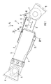
- eine Seitenansicht eines Hydraulikzylinders mit schalenartiger Schutzhülse,
- Fig.2
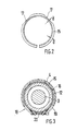
- eine Ansicht in Pfeilrichtung X auf einen am Zylindergehäuse gehaltenen Gleitring gesehen und
- Fig.3
- einen Schnitt nach der Linie III-III der Fig.1.
- Die Schutzvorrichtung 1 für einen Hydraulikzylinder 2 umfaßt im wesentlichen ein die Kolbenstange 3 des Hydraulikzylinders teilweise abdeckende schalenartige Schutzhülse 4. Der Hydraulikzylinder 2 ist mit seinem einen gehäuseseitigen Lagerauge 5 am Fahrzeugaufbau 6 und mit seinem stangenseitigen Lagerauge 7 an einem Schild 8 oder dergleichen Arbeitsgerät gelenkig befestigt.
- Die schalenartige Schutzhülse 4 ist mit einem Halter 9 fest verbunden, der wiederum zwischen Schenkeln 10 des Lagerauges 7 um eine horzontale Achse 11 schwenkbar ist.
- Die Schutzhülse 4 umschließt einen Bereich des Zylindergehäuses 12 sowie die bei Arbeitsbewegungen freiliegende Kolbenstange 3. Sie wird hauptsächlich von oben geschützt, d.h. gegen in Pfeilrichtung 14 wirkende äußere Einflüsse.
- Zur gleitenden Abstützung der Schutzhülse 4 ist sie auf einem Gleitring 15 des Zylindergehäuses 12 geführt. Dieser Gleitring 15 besteht aus elastischem Kunststoff und wird über ein Spannband 16 am Gehäuse 12 festgespannt, wie Fig.3 näher zeigt.
- Der Gleitring 15 weist an seinem Umfang tangentiale Abschrägungen 17 auf, die den Ring 15 flexibel gestalten und die Reibung zwischen der Schutzhülse 4 und dem Gleitring 15 vermindern sollen.
- Die schalenartige Schutzhülse 4 weist im unteren Bereich 18 einen durchgehenden Schlitz 19 auf, der einen Freiraum für die Schraube 20 des Spannbandes 16 sowie für eine Druckleitung 21 des Hydraulikzylinders 2 bildet.
- Bei einem Aus- und Einfahren der Kolbenstange 3 in die Pfeilrichtungen 22 und 23 gleitet die Schutzhülse 4 auf dem Gleitring 15 und hält die empfindliche Oberfläche der Kolbenstange 3 gegen von oben in Pfeilrichtung 14 fallende Gegenstände, wie z.B. Steine und dergleichen über den gesamten Arbeitsbereich geschützt.
Claims (5)
- Schutzvorrichtung für eine Kolbenstange eines Hydraulikzylinders an einem Bagger, insbesondere für einen Hydraulikzylinder der zwischen einem Fahrzeugrahmen und einem Planierschild als Arbeitszylinder zum Heben und Senken angeordnet ist, dadurch gekennzeichnet, daß die Vorrichtung (1) eine am Anlenkauge (7) einer Kolbenstange (3) eines Hydraulikzylinders (2) befestigte schalenartige Schutzhülse (4) umfaßt, die am Zylindergehäuse (12) über einen feststehenden Gleitring (15) aufliegend abgestützt ist und die freiliegende Kolbenstange (3) teilweise von oben schützend umschließt.
- Vorrichtung nach Anspruch 1, dadurch gekennzeichnet, daß die Schutzhülse (4) mit einem Halter (9) fest verbunden ist, der am kolbenstangenseitigen Anlenkauge (7) zwischen Schenkeln (10) schwenkbar um eine horizontale Achse (11) angelenkt ist.
- Vorrichtung nach den Ansprüchen 1 oder 2, dadurch gekennzeichnet, daß die Schutzhülse (4) aus einem das Zylindergehäuse (12) teilweise mit umgebenden Rohrelement besteht, welches im unteren Bereich (18) einen durchgehenden einen Freiraum bildenden Längsschlitz (19) aufweist.
- Vorrichtung nach einem oder mehreren der vorhergehenden Ansprüche, dadurch gekennzeichnet, daß der Gleitring (15) aus einem Kunststoff besteht und über ein Spannband (16) am Zylindergehäuse (12) festgesetzt ist.
- Vorrichtung nach einem oder mehreren der vorhergehenden Ansprüche, dadurch gekennzeichnet, daß der Gleitring (15) über den Umfang verteilte tangentiale Abschrägungen (17) aufweist, die eine geringere Wanddicke (d) aufweisen als die übrige Wandung des Ringes (15).
Applications Claiming Priority (2)
| Application Number | Priority Date | Filing Date | Title |
|---|---|---|---|
| DE4010225 | 1990-03-30 | ||
| DE4010225A DE4010225A1 (de) | 1990-03-30 | 1990-03-30 | Schutzvorrichtung fuer eine kolbenstange eines hydraulikzylinders |
Publications (2)
| Publication Number | Publication Date |
|---|---|
| EP0450156A1 true EP0450156A1 (de) | 1991-10-09 |
| EP0450156B1 EP0450156B1 (de) | 1996-03-27 |
Family
ID=6403399
Family Applications (1)
| Application Number | Title | Priority Date | Filing Date |
|---|---|---|---|
| EP90122461A Expired - Lifetime EP0450156B1 (de) | 1990-03-30 | 1990-11-26 | Schutzvorrichtung für eine Kolbenstange eines Hydraulikzylinders |
Country Status (6)
| Country | Link |
|---|---|
| US (1) | US5152351A (de) |
| EP (1) | EP0450156B1 (de) |
| JP (1) | JPH04222725A (de) |
| AT (1) | ATE136082T1 (de) |
| DE (2) | DE4010225A1 (de) |
| NO (1) | NO175649C (de) |
Cited By (2)
| Publication number | Priority date | Publication date | Assignee | Title |
|---|---|---|---|---|
| EP2514297A1 (de) * | 2011-04-19 | 2012-10-24 | CLAAS Selbstfahrende Erntemaschinen GmbH | Selbstfahrende Erntemaschine |
| EP2933388A1 (de) * | 2014-04-18 | 2015-10-21 | Caterpillar Work Tools B. V. | Hydraulikzylinderabdeckung |
Families Citing this family (20)
| Publication number | Priority date | Publication date | Assignee | Title |
|---|---|---|---|---|
| US5386652A (en) * | 1993-11-12 | 1995-02-07 | Allied Gator, Inc. | Cylinder guard |
| US5383563A (en) * | 1994-02-10 | 1995-01-24 | Caterpillar Inc. | Outrigger and guard assembly |
| US6843005B2 (en) * | 2002-11-14 | 2005-01-18 | Rockland, Inc. | Grappling attachment for excavating machines and the like |
| US6659194B1 (en) * | 2002-11-22 | 2003-12-09 | Samuel C. Thompson | Blade angle adjustment system |
| ITRM20030438A1 (it) * | 2003-09-24 | 2005-03-25 | Jolly Drive S R L | Dispositivo di protezione dalla vegetazione marina |
| KR100723579B1 (ko) * | 2004-05-04 | 2007-05-31 | 볼보 컨스트럭션 이키프먼트 홀딩 스웨덴 에이비 | 이음을 방지하는 실린더 보호 장치 |
| DE102004030289A1 (de) * | 2004-06-23 | 2006-01-12 | Ina-Schaeffler Kg | Schutzelement für eine vormontierte Einheit, insbesondere für eine Spannvorrichtung eines Umschlingungsmitteltriebes |
| JP4038197B2 (ja) * | 2004-07-01 | 2008-01-23 | ヤンマー株式会社 | シリンダの保護装置 |
| US7681657B2 (en) * | 2004-12-09 | 2010-03-23 | Deere & Company | Debris guard |
| US7594466B2 (en) * | 2007-01-12 | 2009-09-29 | Rotobec Inc. | Actuator with a protective sleeve for a piston |
| JP4759690B2 (ja) * | 2008-01-29 | 2011-08-31 | ヤンマー建機株式会社 | 旋回作業車 |
| JP2009215698A (ja) * | 2008-03-06 | 2009-09-24 | Yanmar Co Ltd | 作業車の排土装置 |
| WO2010087792A1 (en) | 2009-01-28 | 2010-08-05 | Deere & Company | Bucket cylinder debris guard |
| AU2012388831B2 (en) * | 2012-08-27 | 2017-10-12 | Komatsu Forest Ab | Method and protective arrangement for linear control and actuator means that are components of a tree harvester of a forestry machine |
| CN104454776A (zh) * | 2014-11-25 | 2015-03-25 | 无锡市晶瑜冶金机械有限公司 | 步进炉中平移油缸的安装结构 |
| CN104696313B (zh) * | 2015-03-13 | 2017-03-22 | 山东钢铁股份有限公司 | 一种防护液压缸的水膜装置及其防护方法 |
| CN106560565B (zh) * | 2016-01-08 | 2019-01-25 | 徐工集团工程机械股份有限公司 | 地下铲运机安全保护控制方法、装置和系统 |
| JP6691081B2 (ja) * | 2017-08-28 | 2020-04-28 | 日立建機株式会社 | ショートリーチ型油圧ショベル |
| CN108487364B (zh) * | 2018-03-13 | 2020-07-21 | 柳州柳工挖掘机有限公司 | 挖掘机铲斗油缸防护机构 |
| CA3155250A1 (en) * | 2019-10-25 | 2021-04-29 | Robert Ray | A hydraulic cylinder piston rod protection system |
Citations (6)
| Publication number | Priority date | Publication date | Assignee | Title |
|---|---|---|---|---|
| GB770866A (en) * | 1954-07-01 | 1957-03-27 | John Raymond Austin Sr | A guard for a piston rod of a piston and cylinder actuator |
| DE1601715A1 (de) * | 1968-03-09 | 1970-08-13 | Rolf Dohrendorf | Hydraulische Einrichtung,insbesondere zum Antrieb von Baumaschinen |
| US3997986A (en) * | 1975-10-09 | 1976-12-21 | Caterpillar Tractor Co. | Guard for hydraulic cylinder rods |
| EP0048362A2 (de) * | 1980-09-24 | 1982-03-31 | Josef Martin Feuerungsbau GmbH | Schutzvorrichtungen für Kolbenstangen von Arbeitszylindern, insbesondere für Feuerungsanlagen |
| DE3731734A1 (de) * | 1987-09-21 | 1989-04-06 | Fritz Hildebrandt | Arbeitsmaschine mit hydraulikzylinder |
| DE3803964A1 (de) * | 1988-02-10 | 1989-08-24 | Festo Kg | Schutzvorrichtung |
Family Cites Families (6)
| Publication number | Priority date | Publication date | Assignee | Title |
|---|---|---|---|---|
| GB189713587A (en) * | 1897-06-02 | 1897-09-25 | Adolph Proschinsky | Improvements in Air Pumps for Bicycles. |
| US2730823A (en) * | 1951-07-30 | 1956-01-17 | John F Cassidy | Bulldozer blade |
| US2983059A (en) * | 1957-04-29 | 1961-05-09 | Deere & Co | Hydraulic motor assembly |
| GB1415257A (en) * | 1973-01-19 | 1975-11-26 | Girling Ltd | Gas springs |
| US3982648A (en) * | 1975-11-10 | 1976-09-28 | International Harvester Company | Lift arm safety bar |
| US4074769A (en) * | 1976-04-28 | 1978-02-21 | J. I. Case Company | Bulldozer blade control |
-
1990
- 1990-03-30 DE DE4010225A patent/DE4010225A1/de active Granted
- 1990-11-26 AT AT90122461T patent/ATE136082T1/de not_active IP Right Cessation
- 1990-11-26 EP EP90122461A patent/EP0450156B1/de not_active Expired - Lifetime
- 1990-11-26 DE DE59010249T patent/DE59010249D1/de not_active Expired - Fee Related
-
1991
- 1991-03-20 US US07/672,426 patent/US5152351A/en not_active Expired - Fee Related
- 1991-03-27 JP JP3063328A patent/JPH04222725A/ja active Pending
- 1991-03-27 NO NO911267A patent/NO175649C/no unknown
Patent Citations (6)
| Publication number | Priority date | Publication date | Assignee | Title |
|---|---|---|---|---|
| GB770866A (en) * | 1954-07-01 | 1957-03-27 | John Raymond Austin Sr | A guard for a piston rod of a piston and cylinder actuator |
| DE1601715A1 (de) * | 1968-03-09 | 1970-08-13 | Rolf Dohrendorf | Hydraulische Einrichtung,insbesondere zum Antrieb von Baumaschinen |
| US3997986A (en) * | 1975-10-09 | 1976-12-21 | Caterpillar Tractor Co. | Guard for hydraulic cylinder rods |
| EP0048362A2 (de) * | 1980-09-24 | 1982-03-31 | Josef Martin Feuerungsbau GmbH | Schutzvorrichtungen für Kolbenstangen von Arbeitszylindern, insbesondere für Feuerungsanlagen |
| DE3731734A1 (de) * | 1987-09-21 | 1989-04-06 | Fritz Hildebrandt | Arbeitsmaschine mit hydraulikzylinder |
| DE3803964A1 (de) * | 1988-02-10 | 1989-08-24 | Festo Kg | Schutzvorrichtung |
Cited By (7)
| Publication number | Priority date | Publication date | Assignee | Title |
|---|---|---|---|---|
| EP2514297A1 (de) * | 2011-04-19 | 2012-10-24 | CLAAS Selbstfahrende Erntemaschinen GmbH | Selbstfahrende Erntemaschine |
| DE102011002158A1 (de) | 2011-04-19 | 2012-10-25 | Claas Selbstfahrende Erntemaschinen Gmbh | Selbstfahrende Erntemaschine |
| EP2933388A1 (de) * | 2014-04-18 | 2015-10-21 | Caterpillar Work Tools B. V. | Hydraulikzylinderabdeckung |
| WO2015158546A1 (en) * | 2014-04-18 | 2015-10-22 | Caterpillar Work Tools B.V. | Hydraulic cylinder cover |
| CN106164500A (zh) * | 2014-04-18 | 2016-11-23 | 卡特彼勒作业机具有限公司 | 液压缸盖 |
| US10415608B2 (en) | 2014-04-18 | 2019-09-17 | Caterpillar Work Tools B.V. | Hydraulic cylinder cover |
| CN106164500B (zh) * | 2014-04-18 | 2021-09-24 | 卡特彼勒作业机具有限公司 | 液压缸盖 |
Also Published As
| Publication number | Publication date |
|---|---|
| DE59010249D1 (de) | 1996-05-02 |
| NO175649B (de) | 1994-08-01 |
| NO175649C (no) | 1994-11-09 |
| ATE136082T1 (de) | 1996-04-15 |
| JPH04222725A (ja) | 1992-08-12 |
| NO911267D0 (no) | 1991-03-27 |
| US5152351A (en) | 1992-10-06 |
| DE4010225A1 (de) | 1991-10-02 |
| DE4010225C2 (de) | 1993-04-15 |
| NO911267L (no) | 1991-10-01 |
| EP0450156B1 (de) | 1996-03-27 |
Similar Documents
| Publication | Publication Date | Title |
|---|---|---|
| EP0450156A1 (de) | Schutzvorrichtung für eine Kolbenstange eines Hydraulikzylinders | |
| DE69502398T2 (de) | Einstell- und energieaufnahmemechanismus für eine kraftfahrzeuglenksäule | |
| DE19528358C2 (de) | Freischneidegerät | |
| DE2844773C3 (de) | Zahnstangenfokussiervorrichtung für eine Kamera | |
| DE102009037516A1 (de) | Vorrichtung und Verfahren zum Führen von Versorungsleitungen an einem Gelenkroboter | |
| DE4129497B4 (de) | 4-Wege-Sitzhöhenverstellung für einen Fahrzeugsitz | |
| EP0901429B1 (de) | Vorrichtung zum verstellen der position eines aussenspiegels | |
| DE2620112B2 (de) | Markise mit einer Tuchwelle in einem Markisenkasten | |
| DE19851480B4 (de) | Positionsgeber zur Anstellhubwegmessung der Walzen eines Walzgerüstes | |
| DE2944666A1 (de) | Vorrichtung zum ablaengen und biegen der anschlussdraehte von elektrischen bauelementen | |
| DE102018100179B4 (de) | Gelenkarmmarkise mit Druckstab | |
| EP0235571B1 (de) | Spannvorrichtung | |
| DE3433735C2 (de) | ||
| EP0087555A1 (de) | Sonnenschutzrollo | |
| DE2503130C3 (de) | Walzenabstandsmeßvorrichtung | |
| DE1228950B (de) | Vorrichtung zum OEffnen und Schliessen von Schiebedaechern fuer Fahrzeuge, insbesondere Kraftfahrzeuge | |
| DE3035922C2 (de) | ||
| DE944660C (de) | Umlenkeinrichtung fuer Fenstergetriebe | |
| DE2841420A1 (de) | Fernsteuervorrichtung | |
| DE29720381U1 (de) | Rollo, insbesondere für Seitenfenster von Kraftfahrzeugen | |
| DE2857839C2 (de) | Spannvorrichtung | |
| DE2831320C3 (de) | ||
| DE9213969U1 (de) | Fahrradrahmen | |
| DE4220417A1 (de) | Mechanische Zahnstangenlenkung | |
| DE9303400U1 (de) | Längendifferenzausgleich und Vorspannungsgeber für mit Gegenzug ausfahrbare Behänge von Sonnenschutzanlagen und Markisen |
Legal Events
| Date | Code | Title | Description |
|---|---|---|---|
| PUAI | Public reference made under article 153(3) epc to a published international application that has entered the european phase |
Free format text: ORIGINAL CODE: 0009012 |
|
| AK | Designated contracting states |
Kind code of ref document: A1 Designated state(s): AT DE GB SE |
|
| 17P | Request for examination filed |
Effective date: 19911112 |
|
| 17Q | First examination report despatched |
Effective date: 19921217 |
|
| GRAA | (expected) grant |
Free format text: ORIGINAL CODE: 0009210 |
|
| AK | Designated contracting states |
Kind code of ref document: B1 Designated state(s): AT DE GB SE |
|
| REF | Corresponds to: |
Ref document number: 136082 Country of ref document: AT Date of ref document: 19960415 Kind code of ref document: T |
|
| REF | Corresponds to: |
Ref document number: 59010249 Country of ref document: DE Date of ref document: 19960502 |
|
| GBT | Gb: translation of ep patent filed (gb section 77(6)(a)/1977) |
Effective date: 19960501 |
|
| PLBE | No opposition filed within time limit |
Free format text: ORIGINAL CODE: 0009261 |
|
| STAA | Information on the status of an ep patent application or granted ep patent |
Free format text: STATUS: NO OPPOSITION FILED WITHIN TIME LIMIT |
|
| 26N | No opposition filed | ||
| PGFP | Annual fee paid to national office [announced via postgrant information from national office to epo] |
Ref country code: SE Payment date: 19981109 Year of fee payment: 9 |
|
| PGFP | Annual fee paid to national office [announced via postgrant information from national office to epo] |
Ref country code: AT Payment date: 19981118 Year of fee payment: 9 |
|
| PGFP | Annual fee paid to national office [announced via postgrant information from national office to epo] |
Ref country code: GB Payment date: 19981127 Year of fee payment: 9 Ref country code: DE Payment date: 19981127 Year of fee payment: 9 |
|
| PG25 | Lapsed in a contracting state [announced via postgrant information from national office to epo] |
Ref country code: GB Free format text: LAPSE BECAUSE OF NON-PAYMENT OF DUE FEES Effective date: 19991126 Ref country code: AT Free format text: LAPSE BECAUSE OF NON-PAYMENT OF DUE FEES Effective date: 19991126 |
|
| PG25 | Lapsed in a contracting state [announced via postgrant information from national office to epo] |
Ref country code: SE Free format text: LAPSE BECAUSE OF NON-PAYMENT OF DUE FEES Effective date: 19991127 |
|
| EUG | Se: european patent has lapsed |
Ref document number: 90122461.8 |
|
| GBPC | Gb: european patent ceased through non-payment of renewal fee |
Effective date: 19991126 |
|
| PG25 | Lapsed in a contracting state [announced via postgrant information from national office to epo] |
Ref country code: DE Free format text: LAPSE BECAUSE OF NON-PAYMENT OF DUE FEES Effective date: 20000901 |