EP0450157A1 - Tiroir électronique à introduire dans la bâti d'une armoire - Google Patents
Tiroir électronique à introduire dans la bâti d'une armoire Download PDFInfo
- Publication number
- EP0450157A1 EP0450157A1 EP90122556A EP90122556A EP0450157A1 EP 0450157 A1 EP0450157 A1 EP 0450157A1 EP 90122556 A EP90122556 A EP 90122556A EP 90122556 A EP90122556 A EP 90122556A EP 0450157 A1 EP0450157 A1 EP 0450157A1
- Authority
- EP
- European Patent Office
- Prior art keywords
- heat sink
- circuit board
- insert part
- printed circuit
- components
- Prior art date
- Legal status (The legal status is an assumption and is not a legal conclusion. Google has not performed a legal analysis and makes no representation as to the accuracy of the status listed.)
- Granted
Links
- 239000002184 metal Substances 0.000 claims abstract description 16
- 239000004065 semiconductor Substances 0.000 claims abstract description 15
- 238000001816 cooling Methods 0.000 claims abstract description 14
- 238000003780 insertion Methods 0.000 claims description 4
- 230000037431 insertion Effects 0.000 claims description 4
- 238000011156 evaluation Methods 0.000 claims 1
- 238000004519 manufacturing process Methods 0.000 description 3
- 230000001276 controlling effect Effects 0.000 description 1
- 238000005553 drilling Methods 0.000 description 1
- 238000005516 engineering process Methods 0.000 description 1
- 230000005405 multipole Effects 0.000 description 1
- 230000001105 regulatory effect Effects 0.000 description 1
Images

Classifications
-
- H—ELECTRICITY
- H05—ELECTRIC TECHNIQUES NOT OTHERWISE PROVIDED FOR
- H05K—PRINTED CIRCUITS; CASINGS OR CONSTRUCTIONAL DETAILS OF ELECTRIC APPARATUS; MANUFACTURE OF ASSEMBLAGES OF ELECTRICAL COMPONENTS
- H05K7/00—Constructional details common to different types of electric apparatus
- H05K7/20—Modifications to facilitate cooling, ventilating, or heating
- H05K7/2089—Modifications to facilitate cooling, ventilating, or heating for power electronics, e.g. for inverters for controlling motor
- H05K7/209—Heat transfer by conduction from internal heat source to heat radiating structure
Definitions
- the invention relates to an electronic insert part for insertion into the frame of a control cabinet, which has on at least one side a heat sink with cooling fins for dissipating the heat loss of electronic components and at least one printed circuit board equipped with electronic power components, which is arranged essentially parallel to the heat sink, the electronic power components are mounted on the circuit board essentially on the side facing the heat sink and close the cooling fins flush with a plane that is determined by the maximum permissible width of the insert part.
- Such insert parts are e.g. as 19 "slide-in parts, widely used. They can include controls for power plants (including nuclear power plants) or other systems (e.g. electrostatic filters or machine tools).
- the object of the present invention is to use this limited space as effectively as possible, that is to accommodate as many electronic elements as possible in the insert part and to interconnect them.
- the interconnection should also take place in such a way that faulty interconnection is made difficult or impossible.
- circuit board via flat, resilient metal parts with switchable, on the heat sink attached power semiconductors can be electrically conductively connected at substantially the same level as the power semiconductors and the inside of the heat sink is adapted in its contour to the height profile of the components of the printed circuit board and the switchable power semiconductors.
- the cooling fins of the heat sink are arranged such that the bores for fastening the heat sink to the insert part and the components of the circuit board and the switchable power semiconductors on the heat sink lie in the spaces between the cooling fins.
- the metal parts used for the electrical connection have narrow webs to be cut when the power semiconductors are connected to the printed circuit board, as a result of which wiring errors during assembly are almost impossible. If the connecting webs continue to run in holes that serve to receive fasteners, it can practically not happen that during assembly it is forgotten to cut through the connecting webs.
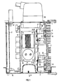
- a heat sink 2 is attached to an insert part on one side by means of screws 1, which serves to dissipate the power loss from thyristors 3 (or other switchable power semiconductors such as GTO's) and from a printed circuit board 4 which has electronic power components 5 is loaded, is delivered.
- the thyristors 3 are fastened to the heat sink 2 with screws 6.
- the cooling fins 7 of the heat sink 2 are arranged so that the holes 8 for the screws are in the gaps between the cooling fins 7.
- Metal parts 9 fastened with screws 21, 22 to the thyristors 3 and to the printed circuit board 4 establish the electrical connection between the thyristors 3 and the printed circuit board 4. Since the metal parts 9 are resilient, the circuit board 4 is automatically aligned at the same level as the thyristors 3 and parallel to the heat sink 2.
- the adjusted spacing of the cooling fins 7 means almost no additional effort, but the effort for deburring the holes 8 to be drilled for the screws 1, 6, which is necessary to ensure that no drilling chips are later arranged in the control cabinet, is advantageous Parts fall and cause short circuits there, greatly reduced.
- the power components 5 of the circuit board 4 are at least largely facing the heat sink 2.
- the contour 10 of the heat sink 2 is optimally adapted to the height profile of the components 5 on the printed circuit board 4. This enables the removal of larger amounts of heat.
- the length of the cooling fins 7 is varied so that their tips are flush with a plane which is determined by the maximum permissible width of the insertion part.
- the external data input and / or output takes place here via a multi-pole plug arranged on the rear of the insert part, for example a Sub-D plug 12.
- the power supply 15 is via one on the rear of the plug-in part, multi-pin power connector 16 to an external power supply and, for example connected to drives to be controlled.
- the metal part 9 is produced by stamping. It is first connected to the thyristors 3 and the circuit board 4 by screws 21 at the points 17. As can be seen from FIG 2, the circuitry of thyristors 3 and circuit board 4 is automatically determined by the shape of the metal part 9. Wrong wiring is no longer possible. The connecting webs 19 must be severed after partial wiring in order to be able to insert the remaining screws 22 into the holes 18. Another advantage of the metal parts 9 is that several can be placed on top of one another if higher currents are to be transmitted.
- the electrically conductive connection of the thyristors 3 to the circuit board 4 through the metal parts 9 automatically also determines the orientation of the circuit board 4 parallel to the heat sink 2 and at the same level as the thyristors 3. Furthermore, since the metal parts 9, as described above, are designed to be resilient, larger manufacturing tolerances are permissible for the power components 5 of the printed circuit board 4 and the thyristors 3.
Landscapes
- Engineering & Computer Science (AREA)
- Microelectronics & Electronic Packaging (AREA)
- Physics & Mathematics (AREA)
- Thermal Sciences (AREA)
- Cooling Or The Like Of Electrical Apparatus (AREA)
Applications Claiming Priority (2)
| Application Number | Priority Date | Filing Date | Title |
|---|---|---|---|
| DE4009289A DE4009289A1 (de) | 1990-03-22 | 1990-03-22 | Elektronisches einschubteil zum einschieben in den rahmen eines schaltschrankes |
| DE4009289 | 1990-03-22 |
Publications (2)
| Publication Number | Publication Date |
|---|---|
| EP0450157A1 true EP0450157A1 (fr) | 1991-10-09 |
| EP0450157B1 EP0450157B1 (fr) | 1994-02-09 |
Family
ID=6402852
Family Applications (1)
| Application Number | Title | Priority Date | Filing Date |
|---|---|---|---|
| EP90122556A Expired - Lifetime EP0450157B1 (fr) | 1990-03-22 | 1990-11-26 | Tiroir électronique à introduire dans la bâti d'une armoire |
Country Status (3)
| Country | Link |
|---|---|
| EP (1) | EP0450157B1 (fr) |
| DE (2) | DE4009289A1 (fr) |
| ES (1) | ES2049896T3 (fr) |
Cited By (1)
| Publication number | Priority date | Publication date | Assignee | Title |
|---|---|---|---|---|
| DE4237632A1 (de) * | 1992-11-07 | 1994-05-11 | Export Contor Ausenhandelsgese | Schaltungsanordnung |
Families Citing this family (4)
| Publication number | Priority date | Publication date | Assignee | Title |
|---|---|---|---|---|
| DE4225675C2 (de) * | 1992-08-04 | 1995-04-20 | Abb Patent Gmbh | Flüssigkeitsgekühltes Stromrichtermodul mit Stromrichtermodulrahmen |
| DE19708873A1 (de) * | 1997-03-05 | 1998-09-10 | Asea Brown Boveri | Gateeinheit für einen hart angesteuerten GTO |
| DE19721610A1 (de) * | 1997-05-23 | 1998-11-26 | Abb Daimler Benz Transp | Drosselbaugruppe für ein Stromrichtergerät |
| ES2160065B1 (es) * | 1999-08-09 | 2003-04-01 | Mecanismos Aux Es Ind S L | Caja de interconexiones para automovil con disipacion termica mejorada. |
Citations (4)
| Publication number | Priority date | Publication date | Assignee | Title |
|---|---|---|---|---|
| FR2580137A1 (en) * | 1985-04-05 | 1986-10-10 | Omron Tateisi Electronics Co | Assembly of electronic components |
| US4769557A (en) * | 1987-02-19 | 1988-09-06 | Allen-Bradley Company, Inc. | Modular electric load controller |
| US4872102A (en) * | 1986-04-28 | 1989-10-03 | Dimensions Unlimited, Inc. | D.C. to A.C. inverter having improved structure providing improved thermal dissipation |
| DE8911408U1 (de) * | 1989-09-25 | 1991-01-31 | Siemens Ag, 8000 Muenchen | Kastenförmiges Gehäuse mit einer eingebauten mehrphasigen elektronischen Halbleiterschaltungsanordnung |
Family Cites Families (8)
| Publication number | Priority date | Publication date | Assignee | Title |
|---|---|---|---|---|
| US4029999A (en) * | 1975-04-10 | 1977-06-14 | Ibm Corporation | Thermally conducting elastomeric device |
| DE3041656A1 (de) * | 1980-11-05 | 1982-05-13 | SEMIKRON Gesellschaft für Gleichrichterbau u. Elektronik mbH, 8500 Nürnberg | Halbleiter-schaltungsaufbau |
| DE3307654A1 (de) * | 1983-03-04 | 1984-09-06 | Robert Bosch Gmbh, 7000 Stuttgart | Elektrisches schaltgeraet im motorraum eines kraftfahrzeugs |
| FR2567350B1 (fr) * | 1984-07-06 | 1987-01-16 | Rv Electronique | Gradateur enfichable perfectionne |
| DE3440756A1 (de) * | 1984-11-08 | 1986-05-07 | CEAG Licht- und Stromversorgungstechnik GmbH, 6800 Mannheim | Stromversorgungsgeraet |
| DE3630830A1 (de) * | 1986-09-10 | 1988-03-17 | Bregenhorn Buetow & Co | Regelgeraet zum steuern von motorischen antrieben |
| DE8630519U1 (de) * | 1986-11-14 | 1987-11-19 | Heidelberger Druckmaschinen Ag, 69115 Heidelberg | Vorrichtung zur Ansteuerung von Elektromotoren |
| DE3643288A1 (de) * | 1986-12-18 | 1988-06-30 | Semikron Elektronik Gmbh | Halbleiterbaueinheit |
-
1990
- 1990-03-22 DE DE4009289A patent/DE4009289A1/de not_active Withdrawn
- 1990-11-26 ES ES90122556T patent/ES2049896T3/es not_active Expired - Lifetime
- 1990-11-26 DE DE90122556T patent/DE59004559D1/de not_active Expired - Fee Related
- 1990-11-26 EP EP90122556A patent/EP0450157B1/fr not_active Expired - Lifetime
Patent Citations (4)
| Publication number | Priority date | Publication date | Assignee | Title |
|---|---|---|---|---|
| FR2580137A1 (en) * | 1985-04-05 | 1986-10-10 | Omron Tateisi Electronics Co | Assembly of electronic components |
| US4872102A (en) * | 1986-04-28 | 1989-10-03 | Dimensions Unlimited, Inc. | D.C. to A.C. inverter having improved structure providing improved thermal dissipation |
| US4769557A (en) * | 1987-02-19 | 1988-09-06 | Allen-Bradley Company, Inc. | Modular electric load controller |
| DE8911408U1 (de) * | 1989-09-25 | 1991-01-31 | Siemens Ag, 8000 Muenchen | Kastenförmiges Gehäuse mit einer eingebauten mehrphasigen elektronischen Halbleiterschaltungsanordnung |
Cited By (2)
| Publication number | Priority date | Publication date | Assignee | Title |
|---|---|---|---|---|
| DE4237632A1 (de) * | 1992-11-07 | 1994-05-11 | Export Contor Ausenhandelsgese | Schaltungsanordnung |
| US5438479A (en) * | 1992-11-07 | 1995-08-01 | Export-Contor Aussenhandelsgesellschaft Mbh | High density, heat-dissipating circuit assembly with accessible components |
Also Published As
| Publication number | Publication date |
|---|---|
| DE4009289A1 (de) | 1991-09-26 |
| DE59004559D1 (de) | 1994-03-24 |
| EP0450157B1 (fr) | 1994-02-09 |
| ES2049896T3 (es) | 1994-05-01 |
Similar Documents
| Publication | Publication Date | Title |
|---|---|---|
| DE102015208968B4 (de) | Kälteplatte mit integrierten elektrischen Komponenten zu deren Kühlung | |
| DE112013004779B4 (de) | Stromrichtvorrichtung | |
| DE3787748T2 (de) | Mittel zum Montieren eines Gehäusemoduls an einer Schalttafel. | |
| DE4225573A1 (de) | Selbstaufbauender bus | |
| EP2790479B1 (fr) | Boîtier destiné à la réception de cartes enfichables électroniques | |
| DE10204866A1 (de) | Wärmeableitmodul | |
| DE4437316C2 (de) | Dezentrale Ein/Ausgabebaugruppe für elektronische Steuerungen | |
| DE3710198C2 (fr) | ||
| DE102004054311A1 (de) | Kühlvorrichtung | |
| EP0450157B1 (fr) | Tiroir électronique à introduire dans la bâti d'une armoire | |
| DE112015002592T5 (de) | Elektrischer Verteiler | |
| DE102015216419A1 (de) | Elektronisches Gerät mit einem Gehäuse mit einer darin angeordneten Leiterplatte | |
| DE3237878C2 (de) | Anordnung zur Abführung der Verlustwärme eines auf einer Leiterplatte montierten Halbleiterbauelementes | |
| DE19642405A1 (de) | Kühlvorrichtung für elektronische Teile | |
| EP0338318A1 (fr) | Dispositif de raidissement et de codage | |
| DE9218583U1 (de) | Selbstaufbauender Bus | |
| EP0428859A2 (fr) | Unité fonctionnelle électrique pour traitement de donnÀ©es | |
| EP3240380A1 (fr) | Système de convertisseur | |
| DE4411192A1 (de) | Aufnahmevorrichtung für ein direkt mit einer Platine verbundenes Bauteil und elektronisches Gerät mit einer solchen Aufnahmevorrichtung | |
| DE60310063T2 (de) | Steueranordnung für heizvorrichtungen | |
| DE102023204440B3 (de) | Elektronische Baugruppe und Steuergerät | |
| DE20300688U1 (de) | Elektrische Anschlussklemme für eine Leiterplatte | |
| DE4242320C1 (de) | Vielpolige Steckverbindung aus einem Stecker und mindestens einem Gegenstecker für Leiterplatten | |
| DE3412129A1 (de) | Einschiebbare baugruppe | |
| DE8533265U1 (de) | Frontplatte für Elektronik-Steckbaugruppen |
Legal Events
| Date | Code | Title | Description |
|---|---|---|---|
| PUAI | Public reference made under article 153(3) epc to a published international application that has entered the european phase |
Free format text: ORIGINAL CODE: 0009012 |
|
| 17P | Request for examination filed |
Effective date: 19901205 |
|
| AK | Designated contracting states |
Kind code of ref document: A1 Designated state(s): CH DE ES FR GB GR LI SE |
|
| 17Q | First examination report despatched |
Effective date: 19930709 |
|
| GRAA | (expected) grant |
Free format text: ORIGINAL CODE: 0009210 |
|
| AK | Designated contracting states |
Kind code of ref document: B1 Designated state(s): CH DE ES FR GB GR LI SE |
|
| REF | Corresponds to: |
Ref document number: 59004559 Country of ref document: DE Date of ref document: 19940324 |
|
| REG | Reference to a national code |
Ref country code: ES Ref legal event code: FG2A Ref document number: 2049896 Country of ref document: ES Kind code of ref document: T3 |
|
| GBT | Gb: translation of ep patent filed (gb section 77(6)(a)/1977) |
Effective date: 19940511 |
|
| ET | Fr: translation filed | ||
| REG | Reference to a national code |
Ref country code: GR Ref legal event code: FG4A Free format text: 3011559 |
|
| PGFP | Annual fee paid to national office [announced via postgrant information from national office to epo] |
Ref country code: GB Payment date: 19941018 Year of fee payment: 5 |
|
| PGFP | Annual fee paid to national office [announced via postgrant information from national office to epo] |
Ref country code: ES Payment date: 19941107 Year of fee payment: 5 |
|
| PGFP | Annual fee paid to national office [announced via postgrant information from national office to epo] |
Ref country code: GR Payment date: 19941111 Year of fee payment: 5 |
|
| PGFP | Annual fee paid to national office [announced via postgrant information from national office to epo] |
Ref country code: SE Payment date: 19941116 Year of fee payment: 5 |
|
| PGFP | Annual fee paid to national office [announced via postgrant information from national office to epo] |
Ref country code: FR Payment date: 19941117 Year of fee payment: 5 |
|
| PLBE | No opposition filed within time limit |
Free format text: ORIGINAL CODE: 0009261 |
|
| STAA | Information on the status of an ep patent application or granted ep patent |
Free format text: STATUS: NO OPPOSITION FILED WITHIN TIME LIMIT |
|
| PGFP | Annual fee paid to national office [announced via postgrant information from national office to epo] |
Ref country code: DE Payment date: 19950119 Year of fee payment: 5 |
|
| EAL | Se: european patent in force in sweden |
Ref document number: 90122556.5 |
|
| 26N | No opposition filed | ||
| PGFP | Annual fee paid to national office [announced via postgrant information from national office to epo] |
Ref country code: CH Payment date: 19950216 Year of fee payment: 5 |
|
| PG25 | Lapsed in a contracting state [announced via postgrant information from national office to epo] |
Ref country code: GB Effective date: 19951126 |
|
| PG25 | Lapsed in a contracting state [announced via postgrant information from national office to epo] |
Ref country code: SE Effective date: 19951127 Ref country code: ES Free format text: LAPSE BECAUSE OF THE APPLICANT RENOUNCES Effective date: 19951127 |
|
| PG25 | Lapsed in a contracting state [announced via postgrant information from national office to epo] |
Ref country code: LI Effective date: 19951130 Ref country code: CH Effective date: 19951130 |
|
| PG25 | Lapsed in a contracting state [announced via postgrant information from national office to epo] |
Ref country code: GR Free format text: THE PATENT HAS BEEN ANNULLED BY A DECISION OF A NATIONAL AUTHORITY Effective date: 19960531 |
|
| REG | Reference to a national code |
Ref country code: CH Ref legal event code: PL |
|
| GBPC | Gb: european patent ceased through non-payment of renewal fee |
Effective date: 19951126 |
|
| PG25 | Lapsed in a contracting state [announced via postgrant information from national office to epo] |
Ref country code: FR Effective date: 19960731 |
|
| REG | Reference to a national code |
Ref country code: GR Ref legal event code: MM2A Free format text: 3011559 |
|
| PG25 | Lapsed in a contracting state [announced via postgrant information from national office to epo] |
Ref country code: DE Effective date: 19960801 |
|
| EUG | Se: european patent has lapsed |
Ref document number: 90122556.5 |
|
| REG | Reference to a national code |
Ref country code: FR Ref legal event code: ST |
|
| REG | Reference to a national code |
Ref country code: ES Ref legal event code: FD2A Effective date: 20010402 |