EP0450174A1 - Dispositif de mesurage opto-électrique du niveau d'interface et de l'indice de réfraction dans des fluides - Google Patents
Dispositif de mesurage opto-électrique du niveau d'interface et de l'indice de réfraction dans des fluides Download PDFInfo
- Publication number
- EP0450174A1 EP0450174A1 EP90124654A EP90124654A EP0450174A1 EP 0450174 A1 EP0450174 A1 EP 0450174A1 EP 90124654 A EP90124654 A EP 90124654A EP 90124654 A EP90124654 A EP 90124654A EP 0450174 A1 EP0450174 A1 EP 0450174A1
- Authority
- EP
- European Patent Office
- Prior art keywords
- light
- convex lens
- sensor body
- plano
- circular cone
- Prior art date
- Legal status (The legal status is an assumption and is not a legal conclusion. Google has not performed a legal analysis and makes no representation as to the accuracy of the status listed.)
- Granted
Links
- 239000012530 fluid Substances 0.000 title 1
- 239000007788 liquid Substances 0.000 claims abstract description 28
- 230000003287 optical effect Effects 0.000 claims abstract description 13
- 239000002360 explosive Substances 0.000 claims description 5
- 239000013307 optical fiber Substances 0.000 claims description 5
- 239000011521 glass Substances 0.000 claims description 3
- 238000005259 measurement Methods 0.000 claims description 2
- 239000004020 conductor Substances 0.000 abstract description 3
- 230000000630 rising effect Effects 0.000 abstract 1
- 230000001419 dependent effect Effects 0.000 description 1
- 238000011156 evaluation Methods 0.000 description 1
- 239000000835 fiber Substances 0.000 description 1
- 231100001261 hazardous Toxicity 0.000 description 1
- 238000012544 monitoring process Methods 0.000 description 1
- 238000011158 quantitative evaluation Methods 0.000 description 1
- 239000004065 semiconductor Substances 0.000 description 1
- 230000035945 sensitivity Effects 0.000 description 1
- 239000002904 solvent Substances 0.000 description 1
- 230000007704 transition Effects 0.000 description 1
- 238000009736 wetting Methods 0.000 description 1
Images
Classifications
-
- G—PHYSICS
- G01—MEASURING; TESTING
- G01N—INVESTIGATING OR ANALYSING MATERIALS BY DETERMINING THEIR CHEMICAL OR PHYSICAL PROPERTIES
- G01N21/00—Investigating or analysing materials by the use of optical means, i.e. using sub-millimetre waves, infrared, visible or ultraviolet light
- G01N21/17—Systems in which incident light is modified in accordance with the properties of the material investigated
- G01N21/41—Refractivity; Phase-affecting properties, e.g. optical path length
- G01N21/43—Refractivity; Phase-affecting properties, e.g. optical path length by measuring critical angle
- G01N21/431—Dip refractometers, e.g. using optical fibres
-
- G—PHYSICS
- G01—MEASURING; TESTING
- G01F—MEASURING VOLUME, VOLUME FLOW, MASS FLOW OR LIQUID LEVEL; METERING BY VOLUME
- G01F23/00—Indicating or measuring liquid level or level of fluent solid material, e.g. indicating in terms of volume or indicating by means of an alarm
- G01F23/22—Indicating or measuring liquid level or level of fluent solid material, e.g. indicating in terms of volume or indicating by means of an alarm by measuring physical variables, other than linear dimensions, pressure or weight, dependent on the level to be measured, e.g. by difference of heat transfer of steam or water
- G01F23/28—Indicating or measuring liquid level or level of fluent solid material, e.g. indicating in terms of volume or indicating by means of an alarm by measuring physical variables, other than linear dimensions, pressure or weight, dependent on the level to be measured, e.g. by difference of heat transfer of steam or water by measuring the variations of parameters of electromagnetic or acoustic waves applied directly to the liquid or fluent solid material
- G01F23/284—Electromagnetic waves
- G01F23/292—Light, e.g. infrared or ultraviolet
- G01F23/2921—Light, e.g. infrared or ultraviolet for discrete levels
- G01F23/2922—Light, e.g. infrared or ultraviolet for discrete levels with light-conducting sensing elements, e.g. prisms
- G01F23/2925—Light, e.g. infrared or ultraviolet for discrete levels with light-conducting sensing elements, e.g. prisms using electrical detecting means
-
- G—PHYSICS
- G01—MEASURING; TESTING
- G01N—INVESTIGATING OR ANALYSING MATERIALS BY DETERMINING THEIR CHEMICAL OR PHYSICAL PROPERTIES
- G01N21/00—Investigating or analysing materials by the use of optical means, i.e. using sub-millimetre waves, infrared, visible or ultraviolet light
- G01N21/17—Systems in which incident light is modified in accordance with the properties of the material investigated
- G01N21/41—Refractivity; Phase-affecting properties, e.g. optical path length
- G01N21/43—Refractivity; Phase-affecting properties, e.g. optical path length by measuring critical angle
- G01N21/431—Dip refractometers, e.g. using optical fibres
- G01N2021/432—Dip refractometers, e.g. using optical fibres comprising optical fibres
Definitions
- the invention relates to a device for optoelectric interface and refractive index measurement in liquids of the type specified in the preamble of the main claim.
- Such interface and refractive index measuring or display devices are used, for example, to measure the fill level or to control the liquid boundary layer of two immiscible liquids of different densities in potentially explosive tanks, for example liquid gas tanks, or containers Solvents or the like are used, the position of a liquid boundary layer being determined from the change in refractive index at the transition between the liquids.
- electrical or electronic control devices must be located outside the hazardous area. The signal controlling the liquid level is therefore generated, transmitted and modulated in the potentially explosive area exclusively using optical means, while the electrical evaluation is carried out at a location remote from the liquid container.
- These interface or refractive index display or measuring devices have a sensor arranged above the liquid level, to which light from at least one light source is supplied via optical waveguides and whose interface, as long as it is located outside the liquid medium, partially reflects the coupled light due to total reflection. The reflected light is in turn fed to a light detector via an optical waveguide. If, on the other hand, the sensor body, which is made of transparent glass or plastic, comes into contact with the liquid level, part of the light striking the interface is decoupled into the liquid due to the total reflection angle falling below the level depending on the refractive index of the medium, and only a small part of it Light detector fed.
- a decisive disadvantage of this arrangement is that the signal swing, that is to say the signal difference, between the measured value when the sensor is not wetted and that when the sensor is wetted is comparatively small. This is due to the fact that a not insignificant part of the light modes guided in the optical waveguide, which are reflected several times on the inner wall of the optical waveguide, already emerge from the interface when the air comes into contact because the total reflection angle falls below. Even if the sensor body is wetted by the liquid, disturbing reflections and a reduction in the signal swing are to be expected, which leads to a sharp reduction in the sensitivity that can be achieved (refractive index difference to the liquid / change in intensity of the reflection).
- the present invention has for its object to provide an optoelectric device of the type specified in the preamble which is particularly suitable for monitoring explosive liquids and which ensures the greatest possible signal swing while avoiding the disadvantages mentioned.
- the basic idea of the invention is to direct the light brought to the sensor body via optical waveguides in parallel by means of a plano-convex lens, to feed it via a circular-cylindrical element without substantial reflection on the cylinder wall to a conical interface rounded at the tip in the shape of a cap, at which it is in the case of Partial or total reflection deflected and again returned to the plano-convex lens parallel to the cylinder wall becomes.
- This focuses the light directed in parallel onto the returning optical waveguide, which, apart from reflection and scattering losses, feeds the injected light to the light detector largely undamped.
- the conical interface is wetted with a liquid, for example from the liquid level of the liquid to be checked, a certain proportion of the light passes through the interface into the liquid medium, so that only a very specific part reaches the light detector.
- the difference in refractive index between the sensor body and the medium determines the total reflection angle and thus the area proportion of the sensor tip, which is shaped as a rounded cap, in which total reflection takes place. This means that only a portion of the light incident on the entire inner surface of the sensor body is reflected back. This proportion of light is directly proportional to the refractive index difference between the medium and the liquid. A quantitative evaluation of the total reflected light portion thus enables the refractive index of the liquid wetting the tip of the sensor body and the use as a refractometer.
- the sensor body with plano-convex lens and circular cone can be made in one piece from transparent glass or plastic.
- the light can be fed in and out either via separate optical fibers (cf. claim 3) or via the Y-shaped branching optical fibers (claim 4).
- the separating layer of liquid levels 45 of individual, immiscible layers determined by their physical density is monitored with the device according to the invention.
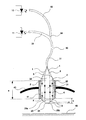
- the sensor body 20 which with its circular-cylindrical middle part 21 penetrates the wall 40 of a container (not shown in detail) and is sealed liquid-tight and gas-tight against it with a schematically indicated seal 41.
- the light 1, 5 to be coupled in and out in the sensor body 20 is fed in or out via optical waveguides 31 to 33.
- a light-emitting diode 10 or another light-emitting semiconductor component is provided as the light source, and a photodiode 11 or similar light receiver is provided as the light detector.
- the light generated by the light emitting diode 10 is fed via the transmitter light waveguide 32 and a branch 34 to the common optical waveguide 31, from the end of which the still undirected light 1 emerges.
- This light 1 is directed in parallel by means of a plano-convex lens 22, as indicated by the rays 2, and in this form is transmitted through the circular cylindrical element 21 of the sensor body 20 without significant reflections on the cylinder walls.
- the side of the sensor body 20 facing the liquid level 45 is in the form of a circular cone 23, with a circular cone height k, which is terminated at the end with a rounded cap 24, with a cap height h, which has, for example, the shape of a spherical cap, the outer surface 23a of which forms the interface.
- the curvature of the cap 24 is dimensioned such that in the vicinity of air or a comparable gaseous atmosphere, a large proportion of the parallel light 2 is totally reflected at the interface 23a in the direction of the light beams 3 and 4, so that it in turn is directed parallel to the plano-convex lens 22 becomes.
- the interface 23a is wetted by the liquid, for example if it is completely or partially immersed in the increased liquid level 45, the parallel-directed light 2 emerges to an extent that is caused by the difference in refractive index is determined between the sensor body and the medium, so that only a very specific portion of the light is returned in the direction of arrows 4. A portion of light reaches the photodiode 11, which acts as a light detector and is suitable for distinguishing different refractive indices.
Landscapes
- Physics & Mathematics (AREA)
- Electromagnetism (AREA)
- General Physics & Mathematics (AREA)
- General Health & Medical Sciences (AREA)
- Analytical Chemistry (AREA)
- Biochemistry (AREA)
- Chemical & Material Sciences (AREA)
- Life Sciences & Earth Sciences (AREA)
- Immunology (AREA)
- Pathology (AREA)
- Health & Medical Sciences (AREA)
- Thermal Sciences (AREA)
- Fluid Mechanics (AREA)
- Investigating Or Analysing Materials By Optical Means (AREA)
- Measurement Of Levels Of Liquids Or Fluent Solid Materials (AREA)
Applications Claiming Priority (2)
| Application Number | Priority Date | Filing Date | Title |
|---|---|---|---|
| DE4010948A DE4010948A1 (de) | 1990-04-05 | 1990-04-05 | Vorrichtung zur optoelektrischen trennschicht- und brechzahlmessung in fluessigkeiten |
| DE4010948 | 1990-04-05 |
Publications (2)
| Publication Number | Publication Date |
|---|---|
| EP0450174A1 true EP0450174A1 (fr) | 1991-10-09 |
| EP0450174B1 EP0450174B1 (fr) | 1994-10-12 |
Family
ID=6403785
Family Applications (1)
| Application Number | Title | Priority Date | Filing Date |
|---|---|---|---|
| EP90124654A Expired - Lifetime EP0450174B1 (fr) | 1990-04-05 | 1990-12-19 | Dispositif de mesurage opto-électrique du niveau d'interface et de l'indice de réfraction dans des fluides |
Country Status (3)
| Country | Link |
|---|---|
| US (1) | US5159834A (fr) |
| EP (1) | EP0450174B1 (fr) |
| DE (2) | DE4010948A1 (fr) |
Cited By (2)
| Publication number | Priority date | Publication date | Assignee | Title |
|---|---|---|---|---|
| EP0981121A3 (fr) * | 1998-08-17 | 2000-06-28 | GARDENA Kress + Kastner GmbH | Détecteur de fluides |
| US20220117313A1 (en) * | 2019-03-12 | 2022-04-21 | Jt International S.A. | Liquid Detecting Method And System, And Cartridge Therewith, For An Electronic Cigarette |
Families Citing this family (21)
| Publication number | Priority date | Publication date | Assignee | Title |
|---|---|---|---|---|
| US5279157A (en) * | 1992-08-03 | 1994-01-18 | Casco Products Corporation | Liquid level monitor |
| US5743135A (en) * | 1993-08-27 | 1998-04-28 | Vlsi Technology, Inc. | Optical-fiber liquid-level monitor |
| US5534708A (en) * | 1993-12-15 | 1996-07-09 | Simmonds Precision Products Inc. | Optical fuel/air/water sensor and detector circuit |
| US5744793A (en) * | 1994-02-28 | 1998-04-28 | Electro-Pro, Inc. | Triangulation position-detection and integrated dispensing valve |
| US5491333A (en) * | 1994-02-28 | 1996-02-13 | Electro-Pro, Inc. | Dispensing method and apparatus that detects the presence and size of a cup and provides automatic fill control |
| US5550369A (en) * | 1994-02-28 | 1996-08-27 | Electro-Pro, Inc. | Triangulation position detection method and apparatus |
| US5399876A (en) * | 1994-03-03 | 1995-03-21 | Simmonds Precision Products, Inc. | Optical point level sensor with lens |
| US5606125A (en) * | 1994-06-28 | 1997-02-25 | Lyons; Kevin | Material level-interface control system |
| US5573041A (en) * | 1994-08-01 | 1996-11-12 | Electro-Pro, Inc. | Dispenser control with ultrasonic position detection |
| CA2199927A1 (fr) * | 1996-03-13 | 1997-09-13 | Simmonds Precision Products, Inc. | Indicateur de niveau liquide optique avec autoverification |
| US6265709B1 (en) | 1997-02-04 | 2001-07-24 | Control Products, Inc. | Apparatus and method for detecting an object using digitally encoded optical data |
| US5902998A (en) * | 1997-02-04 | 1999-05-11 | Control Products, Inc. | Apparatus and method for detecting an object using digitally encoded optical signals |
| US5877863A (en) * | 1997-03-20 | 1999-03-02 | Bayer Corporation | Readhead for a photometric diagnostic instrument |
| US6057772A (en) * | 1997-11-13 | 2000-05-02 | Henny Penny Corporation | Apparatus and method for optically sensing liquid level in cooking vessels |
| US6082419A (en) | 1998-04-01 | 2000-07-04 | Electro-Pro, Inc. | Control method and apparatus to detect the presence of a first object and monitor a relative position of the first or subsequent objects such as container identification and product fill control |
| US6394153B2 (en) | 1998-04-01 | 2002-05-28 | Electro-Pro, Inc. | Control method and apparatus to detect the presence of a first object and monitor a relative position of the first or subsequent objects such as container identification and product fill control |
| DE10206824B4 (de) * | 2002-02-18 | 2005-04-28 | Kautex Textron Gmbh & Co Kg | Verfahren zur optischen Füllstandsbestimmung in flüssigkeitsgefüllten Behältern |
| US6668645B1 (en) | 2002-06-18 | 2003-12-30 | Ti Group Automotive Systems, L.L.C. | Optical fuel level sensor |
| US7017408B2 (en) * | 2004-02-13 | 2006-03-28 | Be Intellectual Property, Inc. | Electro-optic liquid level sensing system for aircraft beverage brewing |
| BR112012000259A8 (pt) * | 2009-07-08 | 2017-12-05 | Koninklijke Philips Electronics Nv | equipamento para administrar um volume liquido em um recipiente, copo e método para a administração de um volume em um recipiente |
| JP6091500B2 (ja) | 2011-06-07 | 2017-03-08 | メジャメント スペシャリティーズ, インコーポレイテッド | 流体検出のための光検出装置、およびそのための方法 |
Citations (3)
| Publication number | Priority date | Publication date | Assignee | Title |
|---|---|---|---|---|
| DE3121287A1 (de) * | 1980-05-31 | 1982-04-08 | Barr & Stroud Ltd., Glasgow, Scotland | "lichtleitfaseroptik fuer laser" |
| DE3247192A1 (de) * | 1982-12-21 | 1984-07-05 | Fraunhofer-Gesellschaft zur Förderung der angewandten Forschung e.V., 8000 München | Faseroptische fluessigkeitsstandsmessvorrichtung |
| DE3302089A1 (de) * | 1983-01-22 | 1984-07-26 | Fraunhofer-Gesellschaft zur Förderung der angewandten Forschung e.V., 8000 München | Faseroptische fluessigkeitsbrechzahl-messvorrichtung (refraktometer) |
Family Cites Families (14)
| Publication number | Priority date | Publication date | Assignee | Title |
|---|---|---|---|---|
| US3808887A (en) * | 1972-02-29 | 1974-05-07 | Eaton Corp | Liquid level monitor |
| US4038650A (en) * | 1975-10-14 | 1977-07-26 | Martin Evans | Fluid level detector and probe assembly |
| DE2717089C3 (de) * | 1977-04-18 | 1979-12-06 | Siemens Ag, 1000 Berlin Und 8000 Muenchen | Anzeigevorrichtung zur Erfassung des Pegelstandes von Flüssigkeiten in Flüssigkeitsbehältern |
| DE7908489U1 (de) * | 1979-03-26 | 1979-06-21 | Hectronic Ag, Buchs, Aargau (Schweiz) | Flammdurchschlagsichere lichtleiter- durchfuehrung |
| AU6957981A (en) * | 1980-04-28 | 1981-11-05 | Economics Laboratory Inc. | Liquid level indicator |
| DE3235591C2 (de) * | 1982-09-25 | 1987-03-26 | Fraunhofer-Gesellschaft zur Förderung der angewandten Forschung e.V., 8000 München | Faseroptische Flüssigkeitsstands-Anzeigevorrichtung |
| DE3243839A1 (de) * | 1982-11-26 | 1984-05-30 | Kromberg & Schubert, 5600 Wuppertal | Vorrichtung zur hoehenstandsmessung von fluessigkeiten in behaeltern, insbesondere fuellstandsanzeige fuer kraftfahrzeuge |
| US4711126A (en) * | 1985-03-13 | 1987-12-08 | 501 Nederlandse Centrale Organisatie Voor Toegepast-Enschappelijk Onderzoek | Sensor for the measurement of the refractive index of a fluid and/or phase boundary between two fluids by means of visible or invisible light |
| DE3606847A1 (de) * | 1986-03-03 | 1987-09-24 | Schott Glaswerke | Faseroptischer sensor fuer fluessigkeitsstandanzeiger oder -niveauregler |
| DE3617717C2 (de) * | 1986-05-27 | 1995-08-17 | Siemens Ag | Faseroptischer Füllstandssensor |
| US4764671A (en) * | 1986-10-03 | 1988-08-16 | Kollmorgen Corporation | Fiber optic fluid sensor using coated sensor tip |
| US4840137A (en) * | 1987-07-01 | 1989-06-20 | Casco Products Corporation | Liquid level gauging apparatus |
| US4873863A (en) * | 1988-11-29 | 1989-10-17 | Bruhl J D | Volumetric leak detection means and method |
| US5054319A (en) * | 1990-09-12 | 1991-10-08 | Fling John J | Liquid level sensor and method |
-
1990
- 1990-04-05 DE DE4010948A patent/DE4010948A1/de not_active Withdrawn
- 1990-12-19 DE DE59007456T patent/DE59007456D1/de not_active Expired - Fee Related
- 1990-12-19 EP EP90124654A patent/EP0450174B1/fr not_active Expired - Lifetime
-
1991
- 1991-04-04 US US07/679,684 patent/US5159834A/en not_active Expired - Fee Related
Patent Citations (3)
| Publication number | Priority date | Publication date | Assignee | Title |
|---|---|---|---|---|
| DE3121287A1 (de) * | 1980-05-31 | 1982-04-08 | Barr & Stroud Ltd., Glasgow, Scotland | "lichtleitfaseroptik fuer laser" |
| DE3247192A1 (de) * | 1982-12-21 | 1984-07-05 | Fraunhofer-Gesellschaft zur Förderung der angewandten Forschung e.V., 8000 München | Faseroptische fluessigkeitsstandsmessvorrichtung |
| DE3302089A1 (de) * | 1983-01-22 | 1984-07-26 | Fraunhofer-Gesellschaft zur Förderung der angewandten Forschung e.V., 8000 München | Faseroptische fluessigkeitsbrechzahl-messvorrichtung (refraktometer) |
Cited By (3)
| Publication number | Priority date | Publication date | Assignee | Title |
|---|---|---|---|---|
| EP0981121A3 (fr) * | 1998-08-17 | 2000-06-28 | GARDENA Kress + Kastner GmbH | Détecteur de fluides |
| US20220117313A1 (en) * | 2019-03-12 | 2022-04-21 | Jt International S.A. | Liquid Detecting Method And System, And Cartridge Therewith, For An Electronic Cigarette |
| US12133554B2 (en) * | 2019-03-12 | 2024-11-05 | Jt International S.A. | Liquid detecting method and system, and cartridge therewith, for an electronic cigarette |
Also Published As
| Publication number | Publication date |
|---|---|
| EP0450174B1 (fr) | 1994-10-12 |
| DE4010948A1 (de) | 1991-10-10 |
| DE59007456D1 (de) | 1994-11-17 |
| US5159834A (en) | 1992-11-03 |
Similar Documents
| Publication | Publication Date | Title |
|---|---|---|
| EP0450174B1 (fr) | Dispositif de mesurage opto-électrique du niveau d'interface et de l'indice de réfraction dans des fluides | |
| DE68915141T2 (de) | Immuntestvorrichtung. | |
| EP0078939B1 (fr) | Dispositif en forme de bâton pour détecter le niveau respectif de liquides dans des récipients, des canaux ou similaires | |
| DE102007003040B4 (de) | Vorrichtung zur optischen Detektion eines Phasenübergangs oder dergleichen | |
| EP0006530A1 (fr) | Capteur de température à fibres optiques | |
| DE2328117B2 (de) | Vorrichtung zur bestimmung eines fluessigkeitsniveaus | |
| DE3630351A1 (de) | Optische vorrichtung | |
| DE68903183T2 (de) | Fiberoptischer fuellstandssensor fuer die diskrete oder kontinuierliche anzeige eines fluessigkeitsstandes. | |
| DE1959612A1 (de) | Vorrichtung zur fotometrischen Messung | |
| DE3113248C2 (de) | Vorrichtung zur Entnahme von Flüssigkeiten aus Behältern im Analysenmaßstab | |
| EP0237850A1 (fr) | Sonde à fibre optique pour indicateur ou régulateur de niveau du liquide | |
| EP0297669A2 (fr) | Procédé pour mesurer un rayonnement optique réfléchi | |
| DE3235591C2 (de) | Faseroptische Flüssigkeitsstands-Anzeigevorrichtung | |
| DE19515365C2 (de) | Faseroptische Lichtschranke | |
| EP0450175B1 (fr) | Dispositif d'indication opto-électrique du niveau d'un liquide | |
| DE3644866C2 (fr) | ||
| CH680020A5 (fr) | ||
| DE3908548A1 (de) | Verfahren zur messung des fluessigkeitsstandes in einem behaelter und messfuehler zur durchfuehrung des verfahrens | |
| DE3328141A1 (de) | Vorrichtung zur ueberwachung eines fluessigkeitsspiegels | |
| DE3422772C2 (de) | Vorrichtung zur berührungslosen Innengewindemessung | |
| DE3302089A1 (de) | Faseroptische fluessigkeitsbrechzahl-messvorrichtung (refraktometer) | |
| DE3336210A1 (de) | Verfahren und vorrichtung zur fuellstandsmessung | |
| EP0430111B1 (fr) | Senseur optique | |
| DE19959279A1 (de) | Verfahren und Vorrichtung zur Füllstandsmessung in einem geschlossenen Behälter | |
| DE3108239A1 (de) | "anordnung und verfahren zur messung optischer wellenlaengen" |
Legal Events
| Date | Code | Title | Description |
|---|---|---|---|
| PUAI | Public reference made under article 153(3) epc to a published international application that has entered the european phase |
Free format text: ORIGINAL CODE: 0009012 |
|
| AK | Designated contracting states |
Kind code of ref document: A1 Designated state(s): AT BE CH DE ES FR GB IT LI NL SE |
|
| 17P | Request for examination filed |
Effective date: 19910831 |
|
| 17Q | First examination report despatched |
Effective date: 19930602 |
|
| GRAA | (expected) grant |
Free format text: ORIGINAL CODE: 0009210 |
|
| AK | Designated contracting states |
Kind code of ref document: B1 Designated state(s): DE |
|
| REF | Corresponds to: |
Ref document number: 59007456 Country of ref document: DE Date of ref document: 19941117 |
|
| EN | Fr: translation not filed | ||
| PLBE | No opposition filed within time limit |
Free format text: ORIGINAL CODE: 0009261 |
|
| STAA | Information on the status of an ep patent application or granted ep patent |
Free format text: STATUS: NO OPPOSITION FILED WITHIN TIME LIMIT |
|
| 26N | No opposition filed | ||
| PGFP | Annual fee paid to national office [announced via postgrant information from national office to epo] |
Ref country code: DE Payment date: 19960120 Year of fee payment: 6 |
|
| PG25 | Lapsed in a contracting state [announced via postgrant information from national office to epo] |
Ref country code: DE Effective date: 19970902 |