EP0450186B1 - Dispositif d'infusion de médicament, avec restriction de la recharge de dose - Google Patents
Dispositif d'infusion de médicament, avec restriction de la recharge de dose Download PDFInfo
- Publication number
- EP0450186B1 EP0450186B1 EP90125189A EP90125189A EP0450186B1 EP 0450186 B1 EP0450186 B1 EP 0450186B1 EP 90125189 A EP90125189 A EP 90125189A EP 90125189 A EP90125189 A EP 90125189A EP 0450186 B1 EP0450186 B1 EP 0450186B1
- Authority
- EP
- European Patent Office
- Prior art keywords
- medication
- valve
- pump
- septum
- fluid
- Prior art date
- Legal status (The legal status is an assumption and is not a legal conclusion. Google has not performed a legal analysis and makes no representation as to the accuracy of the status listed.)
- Expired - Lifetime
Links
- 239000003814 drug Substances 0.000 title claims abstract description 111
- 229940079593 drug Drugs 0.000 title claims abstract description 110
- 238000001802 infusion Methods 0.000 title claims abstract description 41
- 239000012530 fluid Substances 0.000 claims abstract description 124
- 230000037361 pathway Effects 0.000 claims abstract description 16
- 238000012546 transfer Methods 0.000 claims abstract description 3
- 238000002347 injection Methods 0.000 claims description 50
- 239000007924 injection Substances 0.000 claims description 50
- 238000006073 displacement reaction Methods 0.000 claims description 9
- 239000000835 fiber Substances 0.000 claims description 9
- 238000004891 communication Methods 0.000 claims description 8
- 238000011010 flushing procedure Methods 0.000 claims description 3
- 238000007920 subcutaneous administration Methods 0.000 claims description 3
- 230000004888 barrier function Effects 0.000 claims description 2
- 230000002093 peripheral effect Effects 0.000 claims 8
- 238000005086 pumping Methods 0.000 description 32
- 238000000034 method Methods 0.000 description 11
- 238000002483 medication Methods 0.000 description 10
- 239000000463 material Substances 0.000 description 7
- BQJCRHHNABKAKU-KBQPJGBKSA-N morphine Chemical compound O([C@H]1[C@H](C=C[C@H]23)O)C4=C5[C@@]12CCN(C)[C@@H]3CC5=CC=C4O BQJCRHHNABKAKU-KBQPJGBKSA-N 0.000 description 6
- 230000036541 health Effects 0.000 description 5
- NOESYZHRGYRDHS-UHFFFAOYSA-N insulin Chemical compound N1C(=O)C(NC(=O)C(CCC(N)=O)NC(=O)C(CCC(O)=O)NC(=O)C(C(C)C)NC(=O)C(NC(=O)CN)C(C)CC)CSSCC(C(NC(CO)C(=O)NC(CC(C)C)C(=O)NC(CC=2C=CC(O)=CC=2)C(=O)NC(CCC(N)=O)C(=O)NC(CC(C)C)C(=O)NC(CCC(O)=O)C(=O)NC(CC(N)=O)C(=O)NC(CC=2C=CC(O)=CC=2)C(=O)NC(CSSCC(NC(=O)C(C(C)C)NC(=O)C(CC(C)C)NC(=O)C(CC=2C=CC(O)=CC=2)NC(=O)C(CC(C)C)NC(=O)C(C)NC(=O)C(CCC(O)=O)NC(=O)C(C(C)C)NC(=O)C(CC(C)C)NC(=O)C(CC=2NC=NC=2)NC(=O)C(CO)NC(=O)CNC2=O)C(=O)NCC(=O)NC(CCC(O)=O)C(=O)NC(CCCNC(N)=N)C(=O)NCC(=O)NC(CC=3C=CC=CC=3)C(=O)NC(CC=3C=CC=CC=3)C(=O)NC(CC=3C=CC(O)=CC=3)C(=O)NC(C(C)O)C(=O)N3C(CCC3)C(=O)NC(CCCCN)C(=O)NC(C)C(O)=O)C(=O)NC(CC(N)=O)C(O)=O)=O)NC(=O)C(C(C)CC)NC(=O)C(CO)NC(=O)C(C(C)O)NC(=O)C1CSSCC2NC(=O)C(CC(C)C)NC(=O)C(NC(=O)C(CCC(N)=O)NC(=O)C(CC(N)=O)NC(=O)C(NC(=O)C(N)CC=1C=CC=CC=1)C(C)C)CC1=CN=CN1 NOESYZHRGYRDHS-UHFFFAOYSA-N 0.000 description 4
- 230000000474 nursing effect Effects 0.000 description 4
- 229920002379 silicone rubber Polymers 0.000 description 4
- 230000008901 benefit Effects 0.000 description 3
- 229960005181 morphine Drugs 0.000 description 3
- 230000008569 process Effects 0.000 description 3
- 239000000126 substance Substances 0.000 description 3
- 102000004877 Insulin Human genes 0.000 description 2
- 108090001061 Insulin Proteins 0.000 description 2
- 239000004743 Polypropylene Substances 0.000 description 2
- 210000004556 brain Anatomy 0.000 description 2
- 238000010276 construction Methods 0.000 description 2
- 206010012601 diabetes mellitus Diseases 0.000 description 2
- 201000010099 disease Diseases 0.000 description 2
- 208000037265 diseases, disorders, signs and symptoms Diseases 0.000 description 2
- 238000012377 drug delivery Methods 0.000 description 2
- 229940125396 insulin Drugs 0.000 description 2
- 230000007774 longterm Effects 0.000 description 2
- -1 polypropylene Polymers 0.000 description 2
- 229920001155 polypropylene Polymers 0.000 description 2
- 210000003625 skull Anatomy 0.000 description 2
- 230000036642 wellbeing Effects 0.000 description 2
- FAPWRFPIFSIZLT-UHFFFAOYSA-M Sodium chloride Chemical compound [Na+].[Cl-] FAPWRFPIFSIZLT-UHFFFAOYSA-M 0.000 description 1
- 210000000683 abdominal cavity Anatomy 0.000 description 1
- 239000000853 adhesive Substances 0.000 description 1
- 230000001070 adhesive effect Effects 0.000 description 1
- 230000005465 channeling Effects 0.000 description 1
- 210000003109 clavicle Anatomy 0.000 description 1
- 230000000994 depressogenic effect Effects 0.000 description 1
- 238000013461 design Methods 0.000 description 1
- 238000001514 detection method Methods 0.000 description 1
- 238000011161 development Methods 0.000 description 1
- 238000007599 discharging Methods 0.000 description 1
- 238000005516 engineering process Methods 0.000 description 1
- 208000015181 infectious disease Diseases 0.000 description 1
- 238000003780 insertion Methods 0.000 description 1
- 230000037431 insertion Effects 0.000 description 1
- 210000003140 lateral ventricle Anatomy 0.000 description 1
- 238000013508 migration Methods 0.000 description 1
- 230000005012 migration Effects 0.000 description 1
- 238000012986 modification Methods 0.000 description 1
- 230000004048 modification Effects 0.000 description 1
- 230000003119 painkilling effect Effects 0.000 description 1
- 229920001296 polysiloxane Polymers 0.000 description 1
- 230000037452 priming Effects 0.000 description 1
- 230000002035 prolonged effect Effects 0.000 description 1
- 238000000926 separation method Methods 0.000 description 1
- 230000002459 sustained effect Effects 0.000 description 1
Images
Classifications
-
- A—HUMAN NECESSITIES
- A61—MEDICAL OR VETERINARY SCIENCE; HYGIENE
- A61M—DEVICES FOR INTRODUCING MEDIA INTO, OR ONTO, THE BODY; DEVICES FOR TRANSDUCING BODY MEDIA OR FOR TAKING MEDIA FROM THE BODY; DEVICES FOR PRODUCING OR ENDING SLEEP OR STUPOR
- A61M5/00—Devices for bringing media into the body in a subcutaneous, intra-vascular or intramuscular way; Accessories therefor, e.g. filling or cleaning devices, arm-rests
- A61M5/14—Infusion devices, e.g. infusing by gravity; Blood infusion; Accessories therefor
- A61M5/142—Pressure infusion, e.g. using pumps
- A61M5/14244—Pressure infusion, e.g. using pumps adapted to be carried by the patient, e.g. portable on the body
- A61M5/14276—Pressure infusion, e.g. using pumps adapted to be carried by the patient, e.g. portable on the body specially adapted for implantation
- A61M5/1428—Pressure infusion, e.g. using pumps adapted to be carried by the patient, e.g. portable on the body specially adapted for implantation with manual pumping action
Definitions
- This invention relates generally to infusion systems for the administration of medications. More particularly, the present invention relates to a refillable and subcutaneously implantable medication delivery system including means for limiting the total amount of medication which can be infused therethrough over a given period of time.
- a typical drawback of out-patient treatment programs includes the requirement of frequent visits by the patient with the physician and the resultant time and transportation problems. It is recognized that if the patient could be provided adequate home care for extended periods of time, the time between visits with the physician could be lengthened. Such extended home care would benefit the physician, as well as the patient in many circumstances, by permitting the physician to devote more professional time to other important matters.
- an infusion system which allows the patient to administer required medications in precise quantities while minimizing the number of injections required and visits which need be made with a physician.
- Such an infusion system is needed which inherently limits the amount of medication which can be infused into the patient over a given period of time.
- such limitation on the total amount of medication which can be infused over a given period of time can be accomplished independently of the size of a reservoir for storing the medication.
- a novel medication delivery device which may be totally subcutaneously emplaced in the body, includes appropriate devices to prevent the unintended infusion of the medication from the system to the body, is refillable by injection to permit long-term use, and includes an inherent recharge restriction capability for limiting the rate at which medication may be infused to the body while preserving the ability of the patient to self-administer the medication on demand in a safe and reliable manner.
- a novel process is needed for percutaneously controlling the flow of fluid through a subcutaneously implanted infusion system including a manually actuable pump and a valve for controlling the flow of fluid from the pump. The present invention fulfills these needs and provides other related advantages.
- the present invention resides in a medication infusion device useful, for example, in the administration of medication to patient requiring infusions of medication at relatively frequent intervals and over extended periods of time. More particularly, the present invention resides in a medication infusion system which is totally subcutaneously implanted in the patient, and is manually actuated by the application of percutaneous pressure to infuse a measured bolus of medication on demand.
- the infusion system comprises, generally, means for receiving medication into the system by injection, a reservoir fluidly connected to the receiving means in a manner permitting the subcutaneous transfer of medication from the receiving means to the reservoir, and a delivery catheter for directing the medication to a specific location in the body. Means are provided for conducting the medication from the reservoir to the catheter inlet.
- Means are also provided for controlling the flow of medication from the reservoir to the catheter, forming a portion of the conducting means, which include a normally closed valve and a pump for flushing a measured quantity of medication into the catheter when the normally closed valve is opened.
- the valve means and the pump are actuated by manual percutaneous manipulation thereof.
- the invention is characterized in that means are provided for restricting the flow of medication from the reservoir to the pump, and thus limiting the rate the pump is recharged, to restrict the total amount of medication which can be pumped into the catheter over a given period of time.
- the restricting means is positioned within the normally closed valve means and includes a fluid pathway through which medication must pass before entering the pump, wherein manipulation of the valve means to open it occludes the fluid pathway to close a portion of the conducting means defined by the restricting means.
- the controlling means comprises a subcutaneously implantable medication infusion control assembly having a medicament recharge restriction.
- the control assembly includes a self-recharging, manually actuable pump for discharging a measured amount of fluid from a pumping chamber.
- the pump includes a pump inlet in fluid communication with the reservoir, a pump outlet in fluid communication with the normally closed valve, and a resilient crown overlying a floor plate to define the pumping chamber therebetween.
- Means are provided for conducting pump recharge fluid from the receiving means and the reservoir into the pumping chamber, and means are provided for conducting discharge fluids from the pumping chamber to the catheter.
- the control assembly also includes a normally closed valve which is actuable by manual percutaneous manipulation for controlling the flow of discharge fluid from the pumping chamber.
- the normally closed valve forms a portion of the discharge fluid conducting means and includes a resiliently flexible body which defines a fluid flow passageway therethrough.
- a valve member is positioned within the fluid flow passageway to occlude the valve.
- the normally closed valve further includes a valve inlet in fluid communication with the pump outlet, a valve outlet in fluid communication with the catheter inlet, and a valve passageway situated directly between the valve inlet and outlet.
- the valve member is resiliently biased to occlude the valve passageway, and a displacement finger is situated and configured within the valve to displace the valve member and open the valve to fluid flow therethrough when actuated by manual percutaneous pressure.
- the control assembly is further provided with means for restricting the rate of fluid flow through the recharge fluid conducting means.
- the restricting means effectively limits the amount of recharge fluid permitted to enter the pumping chamber over a given period of time.
- the restricting means includes at least one capillary-like fluid pathway through which the recharge fluid must pass before entering the pumping chamber.
- the restricting means is positioned relative to the displacement finger so that manipulation of the normally closed valve to move the displacement finger, which opens the discharge fluid conduit means, occludes the capillary-like fluid pathway restrictor to occlude the recharge fluid conducting means.
- the restricting means includes a wick restrictor having a plurality of wicking fibers situated within an impermeable wick housing.
- the wick restrictor is positioned within a portion of the recharge fluid conducting means so that all fluid drawn into the pumping chamber must first pass through the wick restrictor.
- One end of the wick housing is occluded, and an inlet is provided adjacent to the occluded end through a wall of the wick housing.
- the means for receiving medication into the system by injection comprises an injection port including, generally, an elastomeric outer housing having an integral elastomeric septum, a pair of base members situated within the outer housing and which compress a portion of the septum therebetween, and an outlet.
- the outlet extends from an internal chamber between the septum and the base members, exteriorly through the outer housing.
- Another aspect of the present invention involves a novel process for infusing medication stored within a subcutaneously implanted infusion system.
- a process for percutaneously controlling the flow of fluid through a subcutaneously implanted infusion system including a manually actuable pump having a pump inlet and a pump outlet, and a valve for controlling the flow of fluid from the pump, comprises a number of novel process steps.
- the valve is opened by applying percutaneous pressure thereto, to permit medication in the pump to be discharged through the pump outlet.
- the step of opening the valve includes pressing a housing of the valve downwardly.
- the pump inlet is occluded to prevent medication from entering the pump when the valve is opened.
- the steps of opening the valve and occluding the pump inlet are accomplished simultaneously through the application of the percutaneous pressure to the valve.
- Medication in the pump is discharged through the pump outlet and the valve by applying percutaneous pressure to the pump. This is accomplished by pressing a housing of the pump downwardly to flush fluid from a pump chamber within the pump, wherein the step of flushing fluid from the pump occurs only after the valve is opened.
- valve After the medication has been discharged from the pump, the valve is closed by removing the percutaneous pressure applied thereto, and the pump inlet is opened to permit fluid flow into the pump when the valve is closed.
- the steps of closing the valve and opening the pump inlet are accomplished simultaneously through the withdrawal of percutaneous pressure from the valve.
- the rate at which fluid can flow into the pump through the pump inlet is restricted in order to limit the amount of fluid which can be pumped through the infusion system over a given time period.
- fluid stored in the infusion system is caused to pass through a capillary-like fluid pathway as the fluid is drawn into the pump.
- the capillary-like fluid pathway severely restricts the rate at which fluid would otherwise flow into the pump, to a known flow rate that limits the maximum amount of fluid which can be pumped through the system over a given time period.
- the capillary-like fluid pathway is closed to fluid flow when percutaneous pressure is applied to the valve.
- fluid stored in the infusion system is caused to pass through a plurality of packed wicking fibers.
- the wicking fibers are placed in a fluid flow conduit between the pump and the stored medication, and the medication is introduced at the wicking fibers perpendicularly to their length.
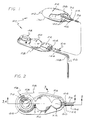
- the present invention is concerned with an improved medication infusion system, generally designated in the accompanying drawings by the reference number 20.
- the medication infusion system 20 generally comprises a variable capacity reservoir 22 connected by a fluid flow conduit 24 to a catheter 26 which directs medications stored in the reservoir to a specific location within a patient.
- a fluid flow control assembly 28 is provided to prevent or reduce the likelihood of an inadvertent infusion into the patient of medication stored in the reservoir 22.
- the control assembly 28 used in the system 20 is situated between the reservoir 22 and the catheter 26 to form a portion of the fluid flow conduit 24.
- the system 20 requires fluid medication to flow through the control assembly 28 before passing into the catheter 26. With the safety and well-being of the patient and all-important consideration in the employment of the system 20, this flow path requirement provides the control over the flow of medication which is critical to the system's safe use. Indeed, the control assembly 28 virtually eliminates the chance of inadvertently infusing more than a very small quantity of medication into the patient by requiring specific sequential and deliberate steps to be taken before a measured volume of fluid can be pumped through the system 20.
- the medication infusion system 20 can substantially reduce the cost of treating some illnesses by eliminating the need for constant medical attention or by reducing the number of required visits which need be made with a physician.
- the overall design of the system 20 permits construction into a variety of configurations for use in many types of different applications.
- the system 20 may be used advantageously by patients requiring regular infusions by minimizing the number of injections received.
- the medication infusion system 20 of the present invention includes means for limiting the maximum amount of medication which can be pumped through the system over a given time period.
- variable capacity reservoir 22 comprises a silicone elastomer shell 30 which can expand and collapse to accommodate changing volumes of fluid medication.
- the reservoir 22 includes an outlet aperture 32 and an outlet connector 34 secured within the aperture 32.
- the outlet connector 34 is designed to engage one end of a first segment of surgical tubing 36 which extends between the reservoir 30 and the control assembly 28.
- a flexible tube 38 having a plurality of tube apertures 40 extends from the reservoir aperture 32 generally rearwardly into the center of the reservoir 22.
- the flexible tube 38 is preferably constructed of a silicone elastomer material having sufficient resiliency to maintain a fluid passageway through its center for channeling fluid medication from the reservoir 22 through the aperture 32 and into the first segment of surgical tubing 36, notwithstanding a collapse of the reservoir shell 30.
- the flexible tube 38 ensures that fluid medication will be able to exit the reservoir 22 even when the reservoir shell 30 collapses in a manner that would otherwise cover the reservoir outlet aperture 32. Such a collapse of the reservoir shell 30 may result from an emptying of fluid from the reservoir 22 during use of the system 20.
- variable capacity reservoir 22 In systems 20 designed for use in the treatment of terminally ill patients, a reservoir 22 having a thirty milliliter capacity would normally hold sufficient amounts of morphine or other similar pain killing drugs to supply patients sufficient quantities of medication for several days.
- the variable capacity reservoir 22 can be remotely located from the insertion point of the catheter 26 in any suitable position as the surgeon chooses, such as in the abdominal cavity, below the ribs or near the clavicle. Indeed, the reservoir 22 can be placed in any soft area of the body which would permit the reservoir to be percutaneously grasped while subcutaneously implanted.
- suture tabs 42 are integrally formed with the reservoir shell 30 to permit the surgeon to anchor the reservoir 22 at the selected location within the patient to prevent migration of the reservoir to an undesirable location.
- the first segment of surgical tubing 36 extends from the outlet connector 34 of the reservoir 22, to a first port 44 of the control assembly 28.
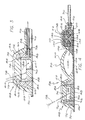
- An end 46 of the surgical tubing 36 is fixed within the first port 44 (FIGS. 1, 2 and 4) in any suitable manner which prevents separation of the first segment of surgical tubing 36 from the control assembly 28.
- the control assembly 28 includes three primary components: an injection port 48, a pump 50 and a normally closed valve 52.
- a recharge fluid flow passageway 54 is provided through the control assembly 28 to direct recharge fluid from the first port 44 to the pump 50.
- the control assembly 28 also provides an injection port fluid outlet passageway 56 between an outlet 58 of the injection port 48, and the recharge fluid flow passageway 54.
- the fluid passageways 54 and 56 intersect, within the control assembly 28, at a port 60 situated generally adjacent to the first port 44 of the control assembly 28.
- the injection port 48 shown in the accompanying drawings is constructed as part of the control assembly unit 28.
- the injection port 48 could be manufactured as a separate component apart from the pump 50 and the normally closed valve 52, since it does not directly interrelate with the function of the pump and the normally closed valve.
- the injection port 48 comprises an upper elastomeric dome 62, a lower elastomeric reinforced sheet 64 which generally underlies the entire control assembly 28, and a pair of base members 66 and 68 housed within the dome 62 above the reinforced sheet 64.
- the upper dome 62 includes a lower flange 70 which is directly sealed to the reinforced sheet 64 by means of a standard adhesive. Accordingly, the dome 62 and reinforced sheet 64 present a continuous elastomeric outer housing for the injection port 48, which helps prevent leakage of drugs injected into the injection port 48 when subcutaneously implanted.
- a frusto-conical side wall 72 which supports an integrally formed septum 74 in a spaced relation above the lower reinforced sheet 64.
- the upper end of the side wall 72 surrounding the septum 74 provides means for percutaneously manually locating the septum when the injection port 48 is subcutaneously implanted. More particularly, the side wall 72 includes a ridge 76 which circumscribes an upper exterior surface of the septum 74.
- the dome 62 is further provided with an outlet connector passageway through a lower portion thereof.
- the septum 74 comprises a thickened portion of silicone elastomer material having characteristics which permit repeated intermittent puncture by a needle 78 for injection of medication from a syringe. Such a needle 78 is preferably 1 mm diameter (twenty-gauge) or smaller.
- the septum 74 includes a septum flange 80 which generally circumscribes a lower end of the septum beneath the ridge portion 76 of the side wall 72.
- the septum flange 80 defines a flange-receiving cavity into which a portion of the outer base member 66 is positioned.
- the outer base member 66 is preferably formed of a rigid polypropylene material and includes a generally frusto-conical ring 82 configured to contiguously engage and support the interior surface of the dome side wall 72.
- the outer base member 66 further includes a rigid upper flange 84 configured to fit within the flange receiving cavity of the dome 62, and circumscribe the septum 74 and engage the septum flange 80. More particularly, the rigid upper flange 84 of the outer base member 66 overlies the septum flange 80 and provides a rigid barrier between the septum flange and the adjacent portions of the dome side wall 72.
- the outer base member 66 further includes an outlet connector passageway 86 in the lower end of the ring 82, which is aligned with the outlet connector passageway of the elastomeric dome 62.
- the inner base member 68 is preferably formed of a rigid polypropylene material and when positioned within the outer base member 66 it defines, with the septum 74, an internal injection chamber 88.
- the inner base member 68 is generally cup-shaped and includes a floor 90 and a continuous wall 92 which extends upwardly from the floor 90.
- the floor 90 and the wall 92 effectively form a needle shield which prevents the needle 78 from passing completely through the injection port 48 after it has entered the injection chamber 88.
- An upper septum-engaging section 94 extends upwardly from the upper edge of the continuous wall 92 and, in the assembled configuration, engages the underside of the septum flange 80.
- the upper septum-engaging section 94 meets the continuous wall 92 at a shoulder.
- the upper septum-engaging section 94 of the inner base member 68 is positioned relative to the outer base member 66 so as to compress the septum flange 80 between the section 94 and the rigid upper flange 84. This creates a fluid-tight seal between the base members 66 and 68, on the one hand, and the septum 74, on the other, and further tends to improve the resealing characteristics of the septum.
- An outlet is provided the injection port 48, which extends from the injection chamber 88 exteriorly through the base members 66 and 68, to receive tubing 96 forming the injection port fluid outlet passageway 56. More specifically, the outlet includes a rigid outlet connector 98 which is integrally formed with the inner base member 68. The outlet connector 98 provides a passageway for fluid injected into the injection chamber 88, to pass out of the injection chamber, through the passageway 56, to either the reservoir 22 or the pump 50.
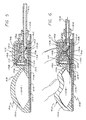
- the pump 50 which can receive fluids from either the reservoir 22 or the injection port 48 through the recharge fluid flow passageway 54, comprises a resiliently flexible crown 100 integrally formed with the dome 62 of the injection port 48.
- the reinforced sheet 64 extends below all three primary components of the control assembly 28, and a rigid floor plate 102 overlies the reinforced sheet 64 beneath the pump and valve components of the control assembly.
- a pumping chamber 104 is defined between the crown 100 and the floor plate 102, and preferably has an evacuation capacity of one milliliter.
- the crown 100 is resiliently biased to generally maintain a dome or arch-shape, but can be deformed to lie substantially flat against the floor plate 102.
- the volume of the pumping chamber 104 can be customized to accommodate various intended uses for the system 20 and the required dosage to be infused into the patient per pumping stroke.
- the crown 100 By constructing the crown 100 of the same material as the septum 74, medication can be injected, if necessary, directly into the pumping chamber 104.
- the floor plate 102 functions as a needle guard, and the puncture site will tend to close upon itself and seal when the needle 78 is removed.
- the pump 50 further includes a pump inlet 106 which communicates with the recharge fluid flow passageway 54, and a pump outlet 108 in fluid communication with an inlet to the normally closed valve 52.
- the recharge fluid flow passageway 54 provides means for conducting pump recharge fluid from either the injection port 48 or the reservoir 22 into the pumping chamber 104.
- the recharge fluid flow passageway 54 directs the recharge fluid over the top of the normally closed valve 52 before directing it into the pump inlet 106. This configuration is desirable in order to permit occlusion of a portion of the recharge passageway 54 when the outer housing for the normally closed valve 52 is pressed downwardly to open the normally closed valve.
- positioned within the recharge passageway 54 are means for restricting the rate of fluid flow through the recharge passageway, which effectively limits the amount of recharge fluid permitted to enter the pumping chamber 104 over a given period of time.
- valve in normal operation after fluid is flushed from the pumping chamber 104 through the pump outlet 108 and through the normally closed valve 52 which has been opened, the valve is immediately shut by the removal of percutaneous pressure therefrom. Closure of the valve 52 prevents back flow of fluid through the valve into the pumping chamber 104. Since the crown 100 is resiliently biased towards its dome-like configuration, a pressure differential is created in the pumping chamber 104 relative to the fluid pressure in the reservoir 22, which tends to draw recharge fluid into the pumping chamber 104 until the crown 100 returns to its dome-like shape.
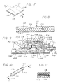
- the means for restricting the rate of fluid flow through the recharge passageway 54 comprises a capillary restrictor 110 (FIGS. 7 and 8) which provides a plurality of capillary-like fluid pathways through which the recharge fluid must pass before entering the pumping chamber 104.
- the capillary restrictor 110 includes a lower sheet 112 having a generally planar upper surface, and an upper sheet 114 having a plurality of grooves 116 extending from one end of the capillary restrictor 110 to the other.
- the capillary restrictor 110 is positioned within the recharge passageway 54 to overlie the normally closed valve 52 so that manual manipulation of the normally closed valve to open it to fluid flow simultaneously compresses the restrictor 110 to effectively occlude the recharge passageway 54.
- the means for restricting the rate of fluid flow through the recharge passageway 54 includes a wick restrictor 118 positioned to partly occupy the pump inlet 106.
- the wick restrictor 118 includes a plurality of wicking fibers 120 situated within an impermeable, cylindrical wick housing 122.
- the wick restrictor 118 is positioned within the recharge passageway 54 to ensure that all fluid drawn into the pumping chamber 104 must first pass through the restrictor 118.
- one end 124 of the wick housing 122 is occluded, for example by means of a silicone sealer, and a plurality of apertures 126 are provided through the cylindrical wall of the housing 122 to provide an inlet for the wick restrictor 118.
- Recharge fluid is then caused to enter the wick restrictor 118 in a direction perpendicular of the length of the fibers 120, and then seep through the fibers before being permitted to pass into the pumping chamber 104.
- the normally closed valve 52 includes a relatively rigid diaphragm support 128 affixed to a portion of the floor plate 102, which provides an inlet 130 for the valve.
- a rigid diaphragm cap 132 is supported upon the diaphragm support 128 and defines, with the diaphragm support, an inlet chamber 134 in fluid communication with the pumping chamber 104, and a valve passageway 136 (formed by the diaphragm cap 132).
- a resiliently flexible valve roof 138 is situated over the diaphragm cap 132 to define, with the cap, an outlet chamber 140 which overlies the inlet chamber 134.
- the valve passageway 136 provides a fluid flow pathway between the inlet chamber 134 and the outlet chamber 140.
- a resiliently flexible valve diaphragm 142 constructed to form a dome-shaped member, is seated circumferentially upon the diaphragm support 128 within the inlet chamber 134 so that a portion of the diaphragm is normally positioned adjacent to the valve passageway 136.
- the valve diaphragm 142 is provided a plurality of diaphragm apertures 144. Unless forcibly displaced away from the portion of the cap 132 surrounding the valve passageway 136, the diaphragm 142 forms a seal which prevents any fluid flow through the normally closed valve 52. It is preferred that the cap 132 and the diaphragm 142 be constructed of materials which will not stick to one another, particularly after long periods of storage.
- a valve housing 146 also defines portions of the recharge passageway 54.
- a portion of the valve roof 138 overlying the outlet chamber 140 includes a downwardly extending diaphragm displacement finger 148 positioned directly above the valve passageway 136.
- the displacement finger 148 is situated for travel through the valve passageway 136 when pressed downwardly, and the diameter of the finger is small enough to prevent occlusion of the valve passageway 136 when the finger is pressed therethrough.
- the finger 148 causes the valve diaphragm 142 to flex downwardly a sufficient distance to break the valve seal and allow fluid to pass through the valve passageway 136 (FIG.
- the housing 146, the valve roof 138 and the diaphragm 142 are each sufficiently resilient to return to their normal configurations and, consequently, close the normally closed valve 52 to fluid flow when the deforming pressure is removed.
- the inclusion of such a normally closed valve 52 in the system 20 enhances the system's utility and safety by preventing the flow of fluid through a discharge fluid flow conduit, partially defined by the normally closed valve 52, in the absence of direct, selectively applied percutaneous pressure on the control assembly 28.
- a valve outlet 150 receives fluid from the outlet chamber 140 and directs it into a second control assembly port 152. As shown best in FIGS. 5 and 6, fixed within the second port 152 is second segment of surgical tubing 154 which conducts fluids discharged from the pumping chamber 104 from the control assembly 28 to the catheter 26.
- the catheter 26 is preferably formed of a barium-impregnated silicone elastomer material which is radiopaque for detection by X-ray photography.
- a catheter inlet 156 is attached to the second segment of surgical tubing 154, and fluid medication exiting the control assembly 28 is directed by the catheter 26 for infusion into a specific portion of the body.
- a catheter 26 can be inserted into the lateral ventricle of the patient's brain.
- a catheter clip 158 as shown in FIG. 1, can be advantageously utilized to hold the catheter 26 in place adjacent to a burr hole through the skull.
- each component may be separately constructed to form individual system components which can be connected to one another by a conduit such as flexible surgical tubing.
- the medication infusion system 20 provides a convenient means for percutaneously controlling the flow of fluid through the subcutaneously implanted infusion system, and yet includes important safety features which prevent the inadvertent, accidental infusion of medication, and further limits the maximum amount of medication which can be infused through the system over a given time period.
- the control assembly 28 is placed over a hard boney surface to provide sufficient resistance to percutaneous pressure which will be applied thereto.
- the system 20 has previously been primed with a sterile saline solution which must be evacuated and replaced with the desired medication.
- Medication is introduced into the infusion system 20 through injection into the injection chamber 88 of the injection port 48. Medication injected into the injection chamber 88 flows through the injection port fluid outlet passageway 56 to the port 60 which intersects with a portion of the recharge fluid flow passageway 54. Here, the injected medication will take the path of least resistance to either fill the reservoir 22 or the pumping chamber 104. When filling the reservoir 22, the fluid medication flows out of the control assembly 28 through the first control assembly port 44, through the first segment of surgical tubing 36 connecting the control assembly to the reservoir, and through the outlet connector 34 fixed within the reservoir aperture 32.
- the pump crown 100 If the pump crown 100 has been depressed to flush priming fluid from the pumping chamber 104, it will attempt to regain its original dome shape. This will create a pressure differential, assuming the normally closed valve 52 is closed, which will draw medication through the recharge fluid flow passageway 54 from either the injection chamber 88 or the reservoir 22.
- the fluid flow restrictor whether it be the capillary restrictor 110 or the wick restrictor 118, effectively limits the rate at which the pumping chamber 104 is permitted to draw-in recharge fluids.
- the normally closed valve 52 To begin the infusion of medication to the patient through the system 20, the normally closed valve 52 must be opened by applying percutaneous pressure thereto, to permit medication in the pumping chamber 104 to be discharged through the pump outlet 108.
- the normally closed valve 52 is opened by manually applying percutaneous downward pressure to the valve housing 146 (FIG. 6). Such downward percutaneous pressure occludes the recharge passageway 54 and forces the displacement finger 148 downwardly through the valve passageway 136 to disengage the valve diaphragm 142 from the valve seat.
- a discharge fluid conduit is opened through the valve 52 to permit medication to be flushed from the pump 50, while simultaneously occluding the recharge passageway 54 and thereby preventing any fluid flow out of the pump inlet 106.
- the upper sheet 114 collapses upon the lower sheet 112 to occlude the capillary-like grooves 116.
- the wick restrictor 118 is utilized (FIGS. 9 through 11)
- the channelling of recharge fluid over the top of the valve 52 permits a portion of the recharge passageway 54 to be occluded by the same downward finger pressure.
- medication in the pumping chamber 104 can be discharged through the pump outlet 108 and the normally closed valve 52 by applying downward percutaneous pressure to the pump 50. This is accomplished by pressing the pump crown 100 downwardly to collapse the pump crown against the floor plate 102. Medication within the pumping chamber 104 is caused to flow from the pump outlet 108 through the valve to the second control assembly port 152, and into the second segment of surgical tubing 154 for delivery to the catheter 26.
- the valve 52 is closed by simply removing the percutaneous pressure applied thereto, and the recharge passageway 54 is opened to permit fluid flow into the pump 50 when the valve is closed.
- the steps of closing the valve 52 and opening the recharge passageway 54 occur simultaneously upon the withdrawal of percutaneous pressure from the valve.
- the pump crown 100 thereafter attempts to regain its original dome-shaped configuration, drawing recharge fluid into the pumping chamber 104 at a rate controlled by either the capillary restrictor 110 or the wick restrictor 118.
- the medication infusion system 20 described above can greatly ease the burden of medical personnel and hospital facilities by providing means for internally storing a large quantity of medication which is to be administered to a patient over an extended period of time.
- various apparatuses can be added to the system 20 for a multitude of purposes, such as the provision of a burr hole reservoir situated adjacent to the skull to facilitate injection of medications directly into the brain.
Landscapes
- Health & Medical Sciences (AREA)
- Animal Behavior & Ethology (AREA)
- Veterinary Medicine (AREA)
- Anesthesiology (AREA)
- Biomedical Technology (AREA)
- Heart & Thoracic Surgery (AREA)
- Hematology (AREA)
- Engineering & Computer Science (AREA)
- General Health & Medical Sciences (AREA)
- Life Sciences & Earth Sciences (AREA)
- Public Health (AREA)
- Vascular Medicine (AREA)
- Media Introduction/Drainage Providing Device (AREA)
- Infusion, Injection, And Reservoir Apparatuses (AREA)
- Acyclic And Carbocyclic Compounds In Medicinal Compositions (AREA)
- Pharmaceuticals Containing Other Organic And Inorganic Compounds (AREA)
Claims (10)
- Ensemble à pompe et réservoir d'injection interne, comprenant un dispositif (48) destiné à recevoir un médicament dans l'ensemble par injection, un réservoir (22) raccordé au dispositif de réception de manière qu'il permette le transfert sous-cutané d'un médicament du dispositif de réception au réservoir, un cathéter (26) destiné à diriger le médicament à un emplacement spécifique dans un corps, le cathéter ayant une entrée et pouvant être placé dans le corps indépendamment de la position du réservoir, un dispositif (24) destiné à conduire le médicament du réservoir à l'entrée du cathéter, et un dispositif (28) de commande de la circulation du médicament du réservoir au cathéter, le dispositif de commande faisant partie du dispositif destiné à conduire le fluide et comprenant une soupape normalement fermée (52) et une pompe (50) destinée à transmettre une quantité mesurée de médicament dans le cathéter lorsque la soupape normalement fermée est ouverte, la soupape et la pompe étant commandées par manipulation percutanée manuelle, caractérisé par un dispositif (110, 118) destiné à limiter le débit de médicament allant du réservoir à la pompe et à limiter ainsi le débit de recharge de la pompe de manière que la quantité totale de médicament qui peut être pompée dans le cathéter pendant une période donnée soit limitée, le dispositif de limitation étant placé dans la soupape normalement fermée et comprenant un trajet (54) de fluide par lequel doit passer le médicament avant d'entrer dans la pompe, la manipulation de la soupape pour son ouverture bouchant le trajet de fluide afin qu'une partie du dispositif destiné à conduire le fluide, délimitée par le dispositif de limitation, soit fermée.
- Ensemble selon la revendication 1, dans lequel le dispositif destiné à recevoir le médicament dans l'ensemble par injection comprend un réceptacle d'injection (48) comprenant un boîtier externe élastomère (62) ayant une cloison élastomère solidaire (74), un premier organe de base (66) placé dans le boîtier externe et coopérant avec une partie périphérique (80) de la cloison dont il est contigu, un second organe de base (68) placé dans le premier organe de base et dans le boîtier externe, le second organe de base coopérant avec la partie périphérique de la cloison opposée au premier organe de base et lui étant contiguë, si bien que la cloison est comprimée entre le premier et le second organe de base, et une sortie (98) partant d'une chambre interne (88) formée entre la cloison et le second organe de base, vers l'extérieur à travers le boîtier externe.
- Ensemble selon la revendication 2, dans lequel le boîtier externe élastomère du réceptacle d'injection comprend un dôme supérieur (62) fixé à une feuille inférieure renforcée (64), le dôme supérieur ayant un flasque inférieur (70) soudé à la feuille renforcée, une paroi latérale tronconique (72) dépassant au-dessus du flasque inférieur, et la cloison qui est formée en une seule pièce avec la paroi latérale et qui est supportée par celle-ci à distance de la feuille inférieure renforcée.
- Ensemble selon la revendication 3, dans lequel la partie périphérique de la cloison est disposée circonférentiellement vers l'extérieur du corps de la cloison entre la paroi latérale et la feuille inférieure renforcée, et le premier organe de base comprend un anneau de forme générale tronconique (82) ayant une configuration telle qu'il peut supporter une surface interne de la paroi latérale et être à son contact, et un flasque supérieur rigide (84) qui recouvre la partie périphérique de la cloison en formant une barrière rigide entre la partie périphérique de la cloison et les parties adjacentes de paroi latérale, le flasque supérieur entourant la cloison et étant au contact de la partie périphérique de la cloison.
- Ensemble selon la revendication 4, dans lequel le second organe de base a une forme de cuvette et comprend un fond (90) et une paroi continue (92) qui remonte du fond, et la paroi continue dépasse du fond afin qu'elle soit au contact d'une surface interne du premier organe de base par emmanchement à force, dans lequel le second organe de base, avec la cloison, délimite la chambre interne d'injection et forme un organe de protection contre une aiguille près de la feuille inférieure renforcée, le second organe de base ayant un tronçon supérieur (94) de contact avec la cloison qui remonte de la paroi continue afin qu'il soit placé sous la partie périphérique de la cloison et comprime la partie périphérique de la cloison entre le flasque supérieur du premier organe de base et le tronçon supérieur de contact avec la cloison du second organe de base.
- Ensemble selon la revendication 1, dans lequel la soupape normalement fermée comprend un corps flexible de soupape (146) qui délimite un passage de circulation de fluide, un organe obturateur (142) placé dans le passage de circulation de fluide et destiné à fermer la soupape, une entrée (130) de soupape qui communique avec la pompe, et une sortie (150) de soupape qui communique avec l'entrée du cathéter, et un passage (136) de soupape placé directement entre l'entrée et la sortie de la soupape, l'organe obturateur étant rappelé élastiquement afin qu'il bouche le passage de la soupape.
- Ensemble selon la revendication 6, dans lequel la soupape normalement fermée comprend un doigt (148) de déplacement dont la position et la configuration sont telles qu'il déplace l'organe obturateur et ouvre la soupape afin que le fluide circule lorsque la soupape est manoeuvrée par manipulation percutanée manuelle.
- Ensemble selon la revendication 7, dans lequel le trajet (110) de fluide du dispositif de limitation est analogue à un capillaire et est placé dans le corps de soupape par rapport au doigt de déplacement de manière que la manipulation de la soupape lors du déplacement du doigt bouche le trajet de fluide analogue à un capillaire.
- Ensemble selon la revendication 1, dans lequel le dispositif de limitation comprend un organe (118) de limitation à mèche ayant plusieurs fibres (120) de mèche placées dans un boîtier imperméable (122) de mèche, et l'organe de limitation à mèche est placé dans une partie du dispositif conduisant le fluide de manière que tout le fluide aspiré dans la pompe doive d'abord passer par l'organe de limitation à mèche.
- Ensemble selon la revendication 9, dans lequel une première extrémité (124) du boîtier de mèche est bouchée, et une entrée (126) est placée près de l'extrémité bouchée et traverse une paroi du boîtier de mèche.
Applications Claiming Priority (2)
| Application Number | Priority Date | Filing Date | Title |
|---|---|---|---|
| US07/503,426 US5152753A (en) | 1990-04-02 | 1990-04-02 | Medication infusion device with dose recharge restriction |
| US503426 | 1990-04-02 |
Publications (2)
| Publication Number | Publication Date |
|---|---|
| EP0450186A1 EP0450186A1 (fr) | 1991-10-09 |
| EP0450186B1 true EP0450186B1 (fr) | 1995-02-15 |
Family
ID=24002046
Family Applications (1)
| Application Number | Title | Priority Date | Filing Date |
|---|---|---|---|
| EP90125189A Expired - Lifetime EP0450186B1 (fr) | 1990-04-02 | 1990-12-21 | Dispositif d'infusion de médicament, avec restriction de la recharge de dose |
Country Status (6)
| Country | Link |
|---|---|
| US (1) | US5152753A (fr) |
| EP (1) | EP0450186B1 (fr) |
| JP (1) | JPH0824720B2 (fr) |
| AT (1) | ATE118360T1 (fr) |
| CA (1) | CA2030767C (fr) |
| DE (1) | DE69017004T2 (fr) |
Cited By (4)
| Publication number | Priority date | Publication date | Assignee | Title |
|---|---|---|---|---|
| US8547239B2 (en) | 2009-08-18 | 2013-10-01 | Cequr Sa | Methods for detecting failure states in a medicine delivery device |
| US8672873B2 (en) | 2009-08-18 | 2014-03-18 | Cequr Sa | Medicine delivery device having detachable pressure sensing unit |
| US9005169B2 (en) | 2007-10-16 | 2015-04-14 | Cequr Sa | Cannula insertion device and related methods |
| US9211378B2 (en) | 2010-10-22 | 2015-12-15 | Cequr Sa | Methods and systems for dosing a medicament |
Families Citing this family (73)
| Publication number | Priority date | Publication date | Assignee | Title |
|---|---|---|---|---|
| US5728061A (en) * | 1988-10-07 | 1998-03-17 | Ahmed; Abdul Mateen | Device and method for treating hydrocephalus |
| US5336188A (en) * | 1989-06-16 | 1994-08-09 | Science Incorporated | Fluid delivery apparatus having a stored energy source |
| DK8391A (da) * | 1991-01-18 | 1992-07-19 | Uno Plast As | Sugepumpe til brug ved udsugning af legemsvaeske fra kropshulrum |
| US5431634A (en) * | 1992-03-06 | 1995-07-11 | Baxter International Inc. | Ambulatory pump |
| DE4402380A1 (de) * | 1994-01-27 | 1995-08-03 | Hans Peter Prof Dr Med Zenner | Implantierbares Dosiersystem |
| US5776103A (en) * | 1995-10-11 | 1998-07-07 | Science Incorporated | Fluid delivery device with bolus injection site |
| US5871484A (en) * | 1995-11-09 | 1999-02-16 | General Orthopedics | Apparatus and method for administering a biologically active substance to a bone |
| US6186982B1 (en) * | 1998-05-05 | 2001-02-13 | Elan Corporation, Plc | Subcutaneous drug delivery device with improved filling system |
| JPH11190281A (ja) * | 1997-10-20 | 1999-07-13 | Seiko Instruments Inc | エアポンプ、エアーチャンバー装置及びエアーチャンバー装置付き腕時計 |
| SE9704769D0 (sv) * | 1997-12-19 | 1997-12-19 | Astra Ab | Medical device |
| WO1999038551A1 (fr) * | 1998-02-02 | 1999-08-05 | Medtronic, Inc. | Dispositif implantable servant a administrer un medicament par perfusion et possedant un clapet de surete |
| US6048328A (en) * | 1998-02-02 | 2000-04-11 | Medtronic, Inc. | Implantable drug infusion device having an improved valve |
| US6193682B1 (en) | 1998-03-16 | 2001-02-27 | Abdul Mateen Ahmed | Low profile neonatal hydrocephalus device and methods |
| US6283944B1 (en) * | 1998-04-30 | 2001-09-04 | Medtronic, Inc. | Infusion systems with patient-controlled dosage features |
| USD405525S (en) | 1998-06-11 | 1999-02-09 | Baxter International Inc. | Patient controlled analgesia actuator |
| US8177762B2 (en) | 1998-12-07 | 2012-05-15 | C. R. Bard, Inc. | Septum including at least one identifiable feature, access ports including same, and related methods |
| US6287293B1 (en) * | 1999-09-28 | 2001-09-11 | C. R. Bard, Inc. | Method and apparatus for locating the injection point of an implanted medical device |
| US6530903B2 (en) | 2000-02-24 | 2003-03-11 | Xiping Wang | Safety syringe |
| US6666845B2 (en) | 2001-01-04 | 2003-12-23 | Advanced Neuromodulation Systems, Inc. | Implantable infusion pump |
| AU2002238147A1 (en) * | 2001-03-01 | 2002-09-19 | David A. Watson | Ingrowth preventing indwelling catheter assembly |
| JP4398723B2 (ja) * | 2001-06-01 | 2010-01-13 | アイ−フロー コーポレイション | 大容量ボーラス装置 |
| EP2077130A3 (fr) * | 2002-02-18 | 2009-09-23 | CeQur ApS | Dispositif d'administration de médicament sous forme fluide |
| US7115108B2 (en) * | 2002-04-02 | 2006-10-03 | Becton, Dickinson And Company | Method and device for intradermally delivering a substance |
| GB2389791B (en) * | 2002-04-30 | 2006-12-13 | Steven Gill | Implantable drug delivery pump |
| US6936035B2 (en) * | 2002-12-31 | 2005-08-30 | I-Flow Corporation | Patient controlled drug administration device |
| CN100423796C (zh) | 2003-01-28 | 2008-10-08 | 丹佛斯公司 | 具有泄漏监控的毛细管载具 |
| US20050124980A1 (en) * | 2003-12-03 | 2005-06-09 | Sanders Scott W. | Port stem marking for catheter placement |
| US20050131388A1 (en) * | 2003-12-16 | 2005-06-16 | Henrich Cheng | Embedded spinal injector |
| KR100640952B1 (ko) * | 2004-12-29 | 2006-11-02 | 동부일렉트로닉스 주식회사 | 반도체 소자의 금속배선 형성방법 |
| US20060184091A1 (en) * | 2005-02-14 | 2006-08-17 | Alcon, Inc. | Liquefaction handpiece |
| US7947022B2 (en) | 2005-03-04 | 2011-05-24 | C. R. Bard, Inc. | Access port identification systems and methods |
| US9474888B2 (en) | 2005-03-04 | 2016-10-25 | C. R. Bard, Inc. | Implantable access port including a sandwiched radiopaque insert |
| US7785302B2 (en) | 2005-03-04 | 2010-08-31 | C. R. Bard, Inc. | Access port identification systems and methods |
| US8029482B2 (en) | 2005-03-04 | 2011-10-04 | C. R. Bard, Inc. | Systems and methods for radiographically identifying an access port |
| US20060212037A1 (en) * | 2005-03-16 | 2006-09-21 | Alcon, Inc. | Pumping chamber for a liquefaction handpiece |
| EP1896117B1 (fr) | 2005-04-27 | 2011-01-12 | C.R.Bard, Inc. | Injecteur de puissance pour l'injection d'agents de contraste dans une ligne intraveineuse |
| US10307581B2 (en) | 2005-04-27 | 2019-06-04 | C. R. Bard, Inc. | Reinforced septum for an implantable medical device |
| US8147455B2 (en) | 2005-04-27 | 2012-04-03 | C. R. Bard, Inc. | Infusion apparatuses and methods of use |
| US8034030B2 (en) * | 2005-05-25 | 2011-10-11 | Palyon Medical (Bvi) Limited | Multi-reservoir implantable pump with variable flow rate capabilities |
| US7708730B2 (en) | 2006-01-30 | 2010-05-04 | Palyon Medical (Bvi) Limited | Template system for multi-reservoir implantable pump |
| US9265912B2 (en) | 2006-11-08 | 2016-02-23 | C. R. Bard, Inc. | Indicia informative of characteristics of insertable medical devices |
| US9642986B2 (en) | 2006-11-08 | 2017-05-09 | C. R. Bard, Inc. | Resource information key for an insertable medical device |
| EP2164559B1 (fr) | 2007-06-20 | 2017-10-25 | Medical Components, Inc. | Orifice d'accès veineux avec indices moulés et/ou radio-opaques |
| MX2010000703A (es) | 2007-07-19 | 2010-07-29 | Medical Components Inc | Ensamble de puerto de acceso venoso con indicaciones que se distinguen para rayos x. |
| US9610432B2 (en) | 2007-07-19 | 2017-04-04 | Innovative Medical Devices, Llc | Venous access port assembly with X-ray discernable indicia |
| US8057437B2 (en) * | 2007-08-31 | 2011-11-15 | Hospira, Inc. | Radially sealing vavle for an infusion set |
| US9579496B2 (en) | 2007-11-07 | 2017-02-28 | C. R. Bard, Inc. | Radiopaque and septum-based indicators for a multi-lumen implantable port |
| DE102008030942A1 (de) | 2008-07-02 | 2010-01-07 | Christoph Miethke Gmbh & Co Kg | Hirnwasserdrainagen |
| US8109912B2 (en) * | 2008-09-12 | 2012-02-07 | Calibra Medical, Inc. | Wearable infusion assembly |
| US8291933B2 (en) * | 2008-09-25 | 2012-10-23 | Novartis Ag | Spring-less check valve for a handpiece |
| ES2906416T3 (es) | 2008-10-31 | 2022-04-18 | Bard Inc C R | Sistemas y métodos para identificar una vía de acceso |
| US8932271B2 (en) | 2008-11-13 | 2015-01-13 | C. R. Bard, Inc. | Implantable medical devices including septum-based indicators |
| US11890443B2 (en) | 2008-11-13 | 2024-02-06 | C. R. Bard, Inc. | Implantable medical devices including septum-based indicators |
| WO2010080081A2 (fr) * | 2009-01-09 | 2010-07-15 | Sidney Rohrscheib | Port d'accès à une greffe apposée |
| US8230744B2 (en) | 2009-05-06 | 2012-07-31 | Cequr Sa | Low-dead volume microfluidic circuit and methods |
| US7967797B2 (en) * | 2009-05-19 | 2011-06-28 | Nexus Medical, Llc | Intravascular valve component with improved valve positioning |
| US8715244B2 (en) | 2009-07-07 | 2014-05-06 | C. R. Bard, Inc. | Extensible internal bolster for a medical device |
| CN102612343B (zh) | 2009-11-17 | 2015-11-25 | C·R·巴德股份有限公司 | 包括锚定装置和标识部分的包覆模制的进入端口 |
| US8814829B2 (en) | 2010-08-12 | 2014-08-26 | Baxter International Inc. | Drug delivery device for fluid restricted patients |
| USD676955S1 (en) | 2010-12-30 | 2013-02-26 | C. R. Bard, Inc. | Implantable access port |
| USD682416S1 (en) | 2010-12-30 | 2013-05-14 | C. R. Bard, Inc. | Implantable access port |
| US8591456B2 (en) | 2011-12-28 | 2013-11-26 | Palyon Medical (Bvi) Limited | Multiple reservoir programmable pump |
| US10517892B2 (en) | 2013-10-22 | 2019-12-31 | Medtronic Minimed, Inc. | Methods and systems for inhibiting foreign-body responses in diabetic patients |
| US20150133861A1 (en) | 2013-11-11 | 2015-05-14 | Kevin P. McLennan | Thermal management system and method for medical devices |
| US10143795B2 (en) | 2014-08-18 | 2018-12-04 | Icu Medical, Inc. | Intravenous pole integrated power, control, and communication system and method for an infusion pump |
| CA2987011C (fr) | 2015-05-26 | 2025-05-13 | Icu Medical, Inc. | Dispositif jetable d'administration de fluide de perfusion destiné à une administration programmable de grands volumes de médicaments |
| NL2015004B1 (en) * | 2015-06-19 | 2017-01-24 | Ipadic B V | Implantable infusion system. |
| DE102016214325A1 (de) * | 2016-08-03 | 2018-02-08 | B. Braun Melsungen Ag | Elastomeres Reservoir einer Infusionspumpe |
| US11197949B2 (en) | 2017-01-19 | 2021-12-14 | Medtronic Minimed, Inc. | Medication infusion components and systems |
| USD939079S1 (en) | 2019-08-22 | 2021-12-21 | Icu Medical, Inc. | Infusion pump |
| EP4291263A1 (fr) * | 2021-02-12 | 2023-12-20 | Medtronic, Inc. | Réservoir de microsphères implantable |
| USD1052728S1 (en) | 2021-11-12 | 2024-11-26 | Icu Medical, Inc. | Medical fluid infusion pump |
| WO2024243296A1 (fr) * | 2023-05-22 | 2024-11-28 | Board Of Regents, The University Of Texas System | Méthodes et systèmes d'irrigation de cavité sous-cutanée fermée |
Family Cites Families (28)
| Publication number | Priority date | Publication date | Assignee | Title |
|---|---|---|---|---|
| US342131A (en) * | 1886-05-18 | Island | ||
| BE664424A (fr) * | ||||
| US3503402A (en) * | 1966-03-23 | 1970-03-31 | Rudolf R Schulte | Shunt device |
| US3527220A (en) * | 1968-06-28 | 1970-09-08 | Fairchild Hiller Corp | Implantable drug administrator |
| US3756243A (en) * | 1971-09-23 | 1973-09-04 | R Schulte | Flow control system for physiological drainage |
| US3768508A (en) * | 1972-01-24 | 1973-10-30 | R Schulte | Valve for controllable release of entrapped body fluids |
| US3827439A (en) * | 1972-10-30 | 1974-08-06 | Heyer Schulte Corp | Plug valve for physiological shunt systems |
| US4360019A (en) * | 1979-02-28 | 1982-11-23 | Andros Incorporated | Implantable infusion device |
| US4364395A (en) * | 1981-06-30 | 1982-12-21 | American Heyer-Schulte Corporation | Low profile shunt system |
| US4544371A (en) * | 1982-10-05 | 1985-10-01 | American Hospital Supply Corporation | Implantable metered dose drug delivery system |
| US4557722A (en) * | 1983-04-13 | 1985-12-10 | Cordis Corporation | Fill port for an implantable dispensing system |
| US4552553A (en) * | 1983-06-30 | 1985-11-12 | Pudenz-Schulte Medical Research Corp. | Flow control valve |
| US4560375A (en) * | 1983-06-30 | 1985-12-24 | Pudenz-Schulte Medical Research Corp. | Flow control valve |
| US4557721A (en) * | 1983-11-29 | 1985-12-10 | Cordis Corporation | Servo valve |
| US4668231A (en) * | 1984-02-15 | 1987-05-26 | Cordis Corporation | Implantable hand-operable dispensers for fluid medicaments |
| US4681560A (en) * | 1984-03-16 | 1987-07-21 | Pudenz-Schulte Medical Research Corp. | Subcutaneous infusion reservoir and pump system |
| US4588394A (en) * | 1984-03-16 | 1986-05-13 | Pudenz-Schulte Medical Research Corp. | Infusion reservoir and pump system |
| US4634427A (en) * | 1984-09-04 | 1987-01-06 | American Hospital Supply Company | Implantable demand medication delivery assembly |
| EP0392566A1 (fr) * | 1984-10-01 | 1990-10-17 | Cook Incorporated | Dispositif d'administration d'insuline implantable |
| JPS61234870A (ja) * | 1984-12-19 | 1986-10-20 | クリエートメディック株式会社 | 皮下埋め込み式リザ−バ− |
| US4681564A (en) * | 1985-10-21 | 1987-07-21 | Landreneau Michael D | Catheter assembly having balloon extended flow path |
| US4681570A (en) * | 1985-12-26 | 1987-07-21 | Dalton Michael J | Peritoneal catheter |
| FR2599260A1 (fr) * | 1986-04-24 | 1987-12-04 | Centre Nat Rech Scient | Dispositif implantable rechargeable pour auto-injection dosee et repetee de medicament. |
| JPS63252170A (ja) * | 1987-04-08 | 1988-10-19 | 富士システムズ株式会社 | 体内埋設型リザ−バ−付カテ−テル |
| US4898584A (en) * | 1988-05-18 | 1990-02-06 | Baxter Healthcare Corporation | Implantable patient-activated fluid delivery device |
| US4898583A (en) * | 1988-05-18 | 1990-02-06 | Baxter Healthcare Corporation | Implantable patient-activated fluid delivery device and outlet valve therefor |
| US4898585A (en) * | 1988-05-18 | 1990-02-06 | Baxter Healthcare Corporation | Implantable patient-activated fluid delivery device with bolus injection port |
| US4898582A (en) * | 1988-08-09 | 1990-02-06 | Pharmetrix Corporation | Portable infusion device assembly |
-
1990
- 1990-04-02 US US07/503,426 patent/US5152753A/en not_active Expired - Lifetime
- 1990-11-23 CA CA002030767A patent/CA2030767C/fr not_active Expired - Fee Related
- 1990-12-21 AT AT90125189T patent/ATE118360T1/de not_active IP Right Cessation
- 1990-12-21 DE DE69017004T patent/DE69017004T2/de not_active Expired - Fee Related
- 1990-12-21 EP EP90125189A patent/EP0450186B1/fr not_active Expired - Lifetime
-
1991
- 1991-01-11 JP JP3001900A patent/JPH0824720B2/ja not_active Expired - Fee Related
Cited By (9)
| Publication number | Priority date | Publication date | Assignee | Title |
|---|---|---|---|---|
| US9005169B2 (en) | 2007-10-16 | 2015-04-14 | Cequr Sa | Cannula insertion device and related methods |
| US9968747B2 (en) | 2007-10-16 | 2018-05-15 | Cequr Sa | Cannula insertion device and related methods |
| US8547239B2 (en) | 2009-08-18 | 2013-10-01 | Cequr Sa | Methods for detecting failure states in a medicine delivery device |
| US8672873B2 (en) | 2009-08-18 | 2014-03-18 | Cequr Sa | Medicine delivery device having detachable pressure sensing unit |
| US9022972B2 (en) | 2009-08-18 | 2015-05-05 | Cequr Sa | Medicine delivery device having detachable pressure sensing unit |
| US9039654B2 (en) | 2009-08-18 | 2015-05-26 | Cequr Sa | Medicine delivery device having detachable pressure sensing unit |
| US9174009B2 (en) | 2009-08-18 | 2015-11-03 | Cequr Sa | Methods for detecting failure states in a medicine delivery device |
| US10300196B2 (en) | 2009-08-18 | 2019-05-28 | Cequr Sa | Medicine delivery device having detachable pressure sensing unit |
| US9211378B2 (en) | 2010-10-22 | 2015-12-15 | Cequr Sa | Methods and systems for dosing a medicament |
Also Published As
| Publication number | Publication date |
|---|---|
| DE69017004D1 (de) | 1995-03-23 |
| CA2030767C (fr) | 1995-04-04 |
| JPH0824720B2 (ja) | 1996-03-13 |
| ATE118360T1 (de) | 1995-03-15 |
| JPH0747136A (ja) | 1995-02-21 |
| US5152753A (en) | 1992-10-06 |
| EP0450186A1 (fr) | 1991-10-09 |
| CA2030767A1 (fr) | 1991-10-03 |
| DE69017004T2 (de) | 1995-06-08 |
Similar Documents
| Publication | Publication Date | Title |
|---|---|---|
| EP0450186B1 (fr) | Dispositif d'infusion de médicament, avec restriction de la recharge de dose | |
| US5085644A (en) | Sterilizable medication infusion device with dose recharge restriction | |
| US4816016A (en) | Subcutaneous infusion reservoir and pump system | |
| US4681560A (en) | Subcutaneous infusion reservoir and pump system | |
| US4588394A (en) | Infusion reservoir and pump system | |
| US6852106B2 (en) | Implantable refillable and ported controlled release drug delivery device | |
| US4634427A (en) | Implantable demand medication delivery assembly | |
| US5137529A (en) | Injection port | |
| EP1075291B1 (fr) | Systemes infuseurs avec moyens de dosage commandes par le patient | |
| US4581020A (en) | Medication delivery device and system for percutaneous administration of medication | |
| US4464178A (en) | Method and apparatus for administration of fluids | |
| US4544371A (en) | Implantable metered dose drug delivery system | |
| US5395324A (en) | Apparatus for the reliable filling of the container of an infusion pump | |
| US4761158A (en) | Subcutaneous infusion reservoir and pump system | |
| US8372039B2 (en) | Infusion pump system | |
| US6997914B2 (en) | Implantable access port | |
| US9993592B2 (en) | Cartridge system for delivery of medicament | |
| WO1999003526A1 (fr) | Ensemble catheter permettant d'acceder par voie percutanee a un orifice sous-cutane | |
| WO1995008359A1 (fr) | Dispositif de medication | |
| AU2001297716A1 (en) | Implantable refillable and rate controlled drug delivery device | |
| WO2013058911A1 (fr) | Système de protection à maille | |
| Gianino et al. | Implantable Delivery Systems |
Legal Events
| Date | Code | Title | Description |
|---|---|---|---|
| PUAI | Public reference made under article 153(3) epc to a published international application that has entered the european phase |
Free format text: ORIGINAL CODE: 0009012 |
|
| AK | Designated contracting states |
Kind code of ref document: A1 Designated state(s): AT BE CH DE DK ES FR GB GR IT LI LU NL SE |
|
| 17P | Request for examination filed |
Effective date: 19910909 |
|
| 17Q | First examination report despatched |
Effective date: 19931026 |
|
| GRAA | (expected) grant |
Free format text: ORIGINAL CODE: 0009210 |
|
| AK | Designated contracting states |
Kind code of ref document: B1 Designated state(s): AT BE CH DE DK ES FR GB GR IT LI LU NL SE |
|
| PG25 | Lapsed in a contracting state [announced via postgrant information from national office to epo] |
Ref country code: IT Free format text: LAPSE BECAUSE OF FAILURE TO SUBMIT A TRANSLATION OF THE DESCRIPTION OR TO PAY THE FEE WITHIN THE PRE;WARNING: LAPSES OF ITALIAN PATENTS WITH EFFECTIVE DATE BEFORE 2007 MAY HAVE OCCURRED AT ANY TIME BEFORE 2007. THE CORRECT EFFECTIVE DATE MAY BE DIFFERENT FROM THE ONE RECORDED.SCRIBED TIME-LIMIT Effective date: 19950215 Ref country code: GR Free format text: LAPSE BECAUSE OF FAILURE TO SUBMIT A TRANSLATION OF THE DESCRIPTION OR TO PAY THE FEE WITHIN THE PRESCRIBED TIME-LIMIT Effective date: 19950215 Ref country code: ES Free format text: THE PATENT HAS BEEN ANNULLED BY A DECISION OF A NATIONAL AUTHORITY Effective date: 19950215 Ref country code: AT Effective date: 19950215 Ref country code: DK Effective date: 19950215 |
|
| REF | Corresponds to: |
Ref document number: 118360 Country of ref document: AT Date of ref document: 19950315 Kind code of ref document: T |
|
| REF | Corresponds to: |
Ref document number: 69017004 Country of ref document: DE Date of ref document: 19950323 |
|
| ET | Fr: translation filed | ||
| PG25 | Lapsed in a contracting state [announced via postgrant information from national office to epo] |
Ref country code: SE Effective date: 19950515 |
|
| PGFP | Annual fee paid to national office [announced via postgrant information from national office to epo] |
Ref country code: FR Payment date: 19951212 Year of fee payment: 6 |
|
| PG25 | Lapsed in a contracting state [announced via postgrant information from national office to epo] |
Ref country code: LU Free format text: LAPSE BECAUSE OF NON-PAYMENT OF DUE FEES Effective date: 19951231 |
|
| PLBE | No opposition filed within time limit |
Free format text: ORIGINAL CODE: 0009261 |
|
| STAA | Information on the status of an ep patent application or granted ep patent |
Free format text: STATUS: NO OPPOSITION FILED WITHIN TIME LIMIT |
|
| 26N | No opposition filed | ||
| PG25 | Lapsed in a contracting state [announced via postgrant information from national office to epo] |
Ref country code: FR Effective date: 19970829 |
|
| REG | Reference to a national code |
Ref country code: FR Ref legal event code: ST |
|
| REG | Reference to a national code |
Ref country code: GB Ref legal event code: IF02 |
|
| PGFP | Annual fee paid to national office [announced via postgrant information from national office to epo] |
Ref country code: GB Payment date: 20041104 Year of fee payment: 15 |
|
| PGFP | Annual fee paid to national office [announced via postgrant information from national office to epo] |
Ref country code: NL Payment date: 20041111 Year of fee payment: 15 |
|
| PGFP | Annual fee paid to national office [announced via postgrant information from national office to epo] |
Ref country code: DE Payment date: 20041230 Year of fee payment: 15 |
|
| PGFP | Annual fee paid to national office [announced via postgrant information from national office to epo] |
Ref country code: CH Payment date: 20050107 Year of fee payment: 15 |
|
| PGFP | Annual fee paid to national office [announced via postgrant information from national office to epo] |
Ref country code: BE Payment date: 20050113 Year of fee payment: 15 |
|
| PG25 | Lapsed in a contracting state [announced via postgrant information from national office to epo] |
Ref country code: GB Free format text: LAPSE BECAUSE OF NON-PAYMENT OF DUE FEES Effective date: 20051221 |
|
| PG25 | Lapsed in a contracting state [announced via postgrant information from national office to epo] |
Ref country code: CH Free format text: LAPSE BECAUSE OF NON-PAYMENT OF DUE FEES Effective date: 20051231 Ref country code: BE Free format text: LAPSE BECAUSE OF NON-PAYMENT OF DUE FEES Effective date: 20051231 Ref country code: LI Free format text: LAPSE BECAUSE OF NON-PAYMENT OF DUE FEES Effective date: 20051231 |
|
| PG25 | Lapsed in a contracting state [announced via postgrant information from national office to epo] |
Ref country code: DE Free format text: LAPSE BECAUSE OF NON-PAYMENT OF DUE FEES Effective date: 20060701 Ref country code: NL Free format text: LAPSE BECAUSE OF NON-PAYMENT OF DUE FEES Effective date: 20060701 |
|
| REG | Reference to a national code |
Ref country code: CH Ref legal event code: PL |
|
| GBPC | Gb: european patent ceased through non-payment of renewal fee |
Effective date: 20051221 |
|
| NLV4 | Nl: lapsed or anulled due to non-payment of the annual fee |
Effective date: 20060701 |
|
| BERE | Be: lapsed |
Owner name: *PUDENZ-SCHULTE MEDICAL RESEARCH CORP. Effective date: 20051231 |