EP0450191B1 - Arrangement de transducteurs - Google Patents
Arrangement de transducteurs Download PDFInfo
- Publication number
- EP0450191B1 EP0450191B1 EP90125415A EP90125415A EP0450191B1 EP 0450191 B1 EP0450191 B1 EP 0450191B1 EP 90125415 A EP90125415 A EP 90125415A EP 90125415 A EP90125415 A EP 90125415A EP 0450191 B1 EP0450191 B1 EP 0450191B1
- Authority
- EP
- European Patent Office
- Prior art keywords
- transducer
- groups
- transducer elements
- grating
- transducer arrangement
- Prior art date
- Legal status (The legal status is an assumption and is not a legal conclusion. Google has not performed a legal analysis and makes no representation as to the accuracy of the status listed.)
- Expired - Lifetime
Links
- 238000011156 evaluation Methods 0.000 claims description 7
- 230000007423 decrease Effects 0.000 claims description 6
- 230000002238 attenuated effect Effects 0.000 claims description 4
- 230000001419 dependent effect Effects 0.000 claims description 4
- 238000012216 screening Methods 0.000 claims 2
- 230000009191 jumping Effects 0.000 claims 1
- 238000013016 damping Methods 0.000 description 13
- 230000035945 sensitivity Effects 0.000 description 12
- 230000003111 delayed effect Effects 0.000 description 11
- 238000005516 engineering process Methods 0.000 description 5
- 238000011161 development Methods 0.000 description 4
- 238000010586 diagram Methods 0.000 description 4
- 230000000737 periodic effect Effects 0.000 description 3
- 230000015572 biosynthetic process Effects 0.000 description 2
- 238000002592 echocardiography Methods 0.000 description 2
- 238000009434 installation Methods 0.000 description 2
- 238000004519 manufacturing process Methods 0.000 description 2
- 238000013459 approach Methods 0.000 description 1
- 230000005540 biological transmission Effects 0.000 description 1
- 238000004364 calculation method Methods 0.000 description 1
- 230000001934 delay Effects 0.000 description 1
- 230000002349 favourable effect Effects 0.000 description 1
- 230000005484 gravity Effects 0.000 description 1
- 238000003780 insertion Methods 0.000 description 1
- 230000037431 insertion Effects 0.000 description 1
- 238000012544 monitoring process Methods 0.000 description 1
- 230000010363 phase shift Effects 0.000 description 1
- 238000004088 simulation Methods 0.000 description 1
- 230000001629 suppression Effects 0.000 description 1
Images


Classifications
-
- H—ELECTRICITY
- H01—ELECTRIC ELEMENTS
- H01Q—ANTENNAS, i.e. RADIO AERIALS
- H01Q1/00—Details of, or arrangements associated with, antennas
- H01Q1/04—Adaptation for subterranean or subaqueous use
-
- H—ELECTRICITY
- H01—ELECTRIC ELEMENTS
- H01Q—ANTENNAS, i.e. RADIO AERIALS
- H01Q21/00—Antenna arrays or systems
- H01Q21/06—Arrays of individually energised antenna units similarly polarised and spaced apart
- H01Q21/22—Antenna units of the array energised non-uniformly in amplitude or phase, e.g. tapered array or binomial array
Definitions
- the invention relates to a transducer arrangement with a plurality of transducer elements for a pivotable directional characteristic of the type mentioned in the preamble.
- transducer arrangements or antennas are required to form directional characteristics in order to determine the direction and distance of wave-emitting or reflecting targets.
- the opening angle of a directional characteristic determines the accuracy of the direction determination or bearing to the target and is determined by the length dimension of the transducer arrangement.
- a clear determination of the direction is only possible, however, if a plurality of transducer elements are arranged equidistantly at a distance from the smallest half wavelength to be received over the length of the transducer arrangement.
- the directional characteristic consists of a main lobe of maximum sensitivity and damped side lobes.
- grating praise Wave incidence from one or more of the directions in which the grating lobes point would simulate a bearing from the direction in which the main lobe is pointing. In order to rule out such incorrect bearing, in an actively working location system, for example, only a narrow sector is irradiated with waves, so that the grating-praise directions lie outside the sector. If sector limitation is not possible, the grating praise is suppressed or attenuated, for example, by constructing the converter arrangement from statistically arranged converter elements, as described, for example, in US Pat. No. 3,553,706.
- PCT application WO 88/10523 corresponding to EP application 0315689 discloses a flat transducer arrangement for transmitting electromagnetic waves, which is composed of transducer elements arranged on concentric circles. Transducer elements of different sizes are used per circle, so that the distances of the transducer elements in the radial direction are different due to the different transducer element sizes.
- the number of identical transducer elements per circle is determined by the transducer element size.
- the length of the radii of the concentric circles does not increase periodically.
- the transducer element size increases from the center and decreases towards the edge of the transducer arrangement, the smallest transducer elements are in the middle.
- grating praise due to the amplitude evaluation of the radiated wave given by the different sizes of the transducer elements, is attenuated, the antenna gain being the same as for a Transducer arrangement with transducer elements of the same size.
- a plurality of directional characteristics pointing in different directions or a pivotable directional characteristic can be formed by phase control of the transducer arrangement.
- a special phase control of the irregularly arranged transducer elements is necessary, so that the effort required for phase-shifting elements to form the direction is considerably greater, particularly in the case of a continuously monitored spatial area, than in the case of a regularly configured antenna configuration.
- a group antenna is described, which is divided into rows and columns.
- Several equidistant transducer elements form a sub-group per line.
- Each sub-group is connected to an electronically controllable phase shifter.
- the subgroups have centers of gravity that are much larger than ⁇ and cause grating praise.
- a Shifting the subgroups against each other and a quasi-random sequence of different row positions in the column direction leads to a reduction in grating praise.
- a prerequisite for this transducer arrangement is that the group antenna be equipped in columns and rows, that is to say in one area, in order to achieve a variation in the alignment of subgroups in the column direction in order to suppress grating praise.
- the interconnection of the transducer elements in sub-groups reduces the number of phase shifters required in the transmitter / receiver to provide different delays.
- grating praise is formed at larger swivel angles, which are due to the spacing of the focal points of the subgroups.
- Different geometric shapes of subgroups are discussed, with the shape of the subgroup repeating and group spacing being the same in the respective antenna configuration.
- This object is achieved by the features mentioned in the characterizing part of claim 1.
- transducer arrangement according to claim 1 is that the manufacture is particularly simple, since the transducer arrangement is based on a grid of half the internal distance of the transducer elements from one another and thus a periodicity.
- This rasterization is also advantageous for the dimensioning of the directional element, so that when a directional characteristic is swiveled or a plurality of directional characteristics pointing in different directions are formed simultaneously
- Converter elements can be assigned multiples of phase rotation or propagation time increments and a special delay or phase value for time compensation of their received signals does not have to be calculated and provided for each converter element.
- the transducer elements within a group have the same distance and from group to group 1.5 times the value of this distance. This measure ensures that at a distance greater than half the wavelength of the associated operating frequency, an incident of waves from the grating-lobe direction does not lead to incorrect bearing, since transducer elements of adjacent groups do not distance d, but 1.5 ⁇ d and received waves at the grating-lobe angle are shifted from group to group by half a wavelength and their received signals are thus canceled.
- the energy received with an equidistant arrangement of the transducer elements from the grating-lobe direction is split and distributed into adjacent angular ranges in the transducer arrangement according to the invention. For groups with the same number of transducers, this results in a directional characteristic with a main lobe and a zero at the associated grating-lobe angle for each swivel angle.
- the grating-lobe angle is dependent on the frequency and the spacing of equidistant transducer elements, apart from the swivel angle into which the directional characteristic points.
- the offset of the groups by 1.5 times the distance gives the advantage that the suppression of grating praise is guaranteed for every swivel angle of the directional characteristic and every frequency.
- the converter arrangement according to the invention is not only for Narrow-band, but also particularly useful for broadband reception, for example in waterborne sound technology for trailing antennas for direction finding of watercraft in the low-frequency range, because the configuration of the transducer arrangement saves transducer elements and thus a price reduction without reducing the bearing accuracy.
- the size of the transducer elements cannot be arranged at a distance smaller than half the wavelength of the received sound waves
- good bundling can be achieved in a particularly cost-saving and advantageous manner in terms of production technology, since the large number of transducer elements is also possible large dimensions of the transducer arrangement can be reduced and costs and weight can be saved with the same output.
- the transducer arrangement according to claim 1 can thus advantageously be used in mine hunting and mine avoidance systems in which incorrect direction finding would be particularly harmful.
- the directional generator is realized by multiples of phase or transit time increments, as a result of which the outlay on circuit technology can be kept low.
- the large number of transducer elements can, however, not only be arranged along a straight line, but also along a curved line that follows, for example, a vehicle wall, one then speaks of a so-called conformed array.
- the converter arrangement according to the invention can also be implemented for a cylinder base.
- the directional characteristics are formed by compensating for the transit time or phases of the received signals from the installation location to a straight line perpendicular to the direction of incidence of the wave and summation. Starting from this straight line, the dimensioning of the transducer arrangement is to be carried out according to claim 1.
- the individual transducer element locations are obtained by vertically shifting from the virtual location on the straight line to the geometric location on the installation line, which is canceled again by the direction generator.
- the surface is divided by lines crossing in the middle and the transducer elements are arranged in groups along the lines.
- the plurality of transducer elements is arranged along a straight line according to the advantageous development of the transducer arrangement according to claim 2 and its number of groups along the straight line is selected according to the advantageous further development according to claim 3 so that a required damping distance between the main lobe and fragmented grating praise in The area around the grating lobe angle is maintained.
- Receiving energy that would be received from the grating-lobe direction in an equidistantly arranged transducer arrangement is distributed by the transducer arrangement according to the invention into adjacent angular ranges between the grating-lobe angle and the swivel angle.
- the angular ranges are from the Number of groups dependent.
- the individual transducer elements per group move closer together, since the group spacings are equal to 1.5 times the value of the transducer spacings within the group.
- the directional characteristic results in lobes that are significantly less sensitive than the main lobe.
- the lobes are fragmented grating lobes that lie symmetrically to the grating-lobe angle, in the remaining angular range up to the main lobe periodically occurring lobes that can be understood as pseudo-grating lobes. Their sensitivity decreases towards the main club.
- the groups have different numbers of transducers, wherein the groups are arranged symmetrically to the center of the transducer arrangement.
- a converter arrangement is particularly advantageous in which the number of converters of the groups closest to the center is greatest and decreases towards the edge of the converter arrangement. This measure also splinters the pseudo-grating praise and, apart from the main lobe, the directional characteristic is continuously attenuated over all angular ranges to approximately the same level, which is lower the larger the number of groups.
- the transducer arrangement consists of two identical sub-bases which are arranged nested one inside the other and are mirror-inverted side-to-side.
- Each of the two sub-bases has a grid that is equal to the distance between the transducers. However, the two sub-bases are shifted from each other by 1.5 times the distance.
- the position and level of all the lobes, except the main lobe are distributed such that when the main lobe is pivoted into the maximum swivel angle, incident wave energy from other angular ranges is damped uniformly, the damping in the angular range around the associated grating lobe angle all the more the greater the number of groups.
- the reduction in the angular range between the grating lobe angle and the direction in which the main lobe points is the same if the number of converters in the groups is not the same.
- the fragmented grating lobes symmetrically around the grating lobe angle level off in particular to the same low level when the number of transducers decreases from the center outwards.
- the specified provision is comparable to the Leverage Act. It will the distance between the center of the transducer arrangement and each individual transducer element of the groups belonging to a sub-base added up to the right and left of the center of the transducer arrangement. A directional characteristic with maximum sensitivity in the main lobe at maximum swivel angle and uniform damping in the other angular range is ensured in that the sum of the distances to the right of the center is equal to the sum of the distances to the left of the center. As a result, the focus of each sub-base is almost on the middle of the transducer arrangement. With this dimensioning it is assumed that the received signals of the transducer elements are added after an amplitude evaluation of "1" in the directional generator.
- the product is formed from the respective distance and the amplitude evaluation factor and the sum of the products for each sub-base taking into account the position of the transducer with respect to the center "Zero".
- the damping by the grating-lobe angle in an angular range of approximately 10 ° is more than 35 dB compared to the sensitivity of the main lobe.
- the fragmented grating praise that limits this angular range has an attenuation of a good 10 dB.
- the attenuation in the angular range up to the swivel angle of the main lobe increases continuously up to values of 30 dB.
- the dimensioning of the number of transducers in the groups depends on the application of the transducer arrangement and is different, for example, in the case of a broadband operation, as is necessary for monitoring a sea area in a trailing antenna, than in the case of narrowband operation, as is e.g. is common in actively working sonar systems, where a high degree of selectivity with regard to echoes from a wide-range, irradiated sector is necessary.
- the transducer arrangement for reception according to claim 7 in which the average number of transducers in the groups is selected so that echoes from directions other than the direction of the main lobe are received with significantly less sensitivity.
- the measure according to claim 8 ensures that the same number of transducer elements always have received signals which cancel each other out while the pulse sweeps across the transducer arrangement.
- the converter arrangements described for the reception case are also suitable for transmission.
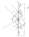
- FIG. 1 shows a transducer arrangement for a waterborne sound system with a large number N of transducer elements which are arranged along a straight line 10.
- the transducer elements are followed by a direction generator (not shown here), which consists of phase shifters with monochromatic reception or from delay elements with broadband reception.
- the received signals of the transducer elements are added instantaneously when sound waves are received from the vertical to the center 11 of the transducer arrangement and form a directional characteristic with a main lobe in the direction of the central perpendicular and secondary lobes.
- the larger the extension L of the transducer arrangement the smaller its opening angle.
- the directional characteristic can be pivoted from the central perpendicular through angle ⁇ by running time or phase control, whereby the maximum swivel angle is the drawn angle ⁇ max .
- the maximum swivel angle is the drawn angle ⁇ max .
- several directional characteristics can be formed, the main lobes of which point at different swivel angles.
- the transducer elements are at a distance d from one another, between groups 21 and 22 or 22 and 23 or 23 and 24 1.5 times the value of the distance d.
- the distance d between the transducer elements is greater than ⁇ / 2, where ⁇ is the smallest wavelength of the received sound wave.
- grating lobe With a swivel angle ⁇ max of the directional characteristic, in addition to side lobes, another lobe with the same sensitivity as the main lobe, the so-called grating lobe, occurs at a grating lobe angle ⁇ , as described, for example, in "Microwave Scanning Antennas" by RC Hansen, Academic Press, New York and London, 1964, shown on page 203.
- sin ⁇ sin ⁇ - n ⁇ / d applies.
- the number of grating-lobe angles ⁇ and their size depend on the distance d of the transducer elements with respect to the wavelength ⁇ of the received wave and on the swivel angle ⁇ . Different grating-lobe angles ⁇ are set for each swivel angle ⁇ and each frequency f.
- ⁇ m + 1 sin ⁇ ⁇ (m + 1.5)
- ⁇ d / c 3/4 sin ⁇ ⁇ ⁇ ⁇ m c + 3/4 sin ⁇ 3/2 ⁇ / c
- the received signal U ⁇ e j ⁇ (t + ⁇ 0 + ⁇ m ) of the transducer element at position A is delayed by ( ⁇ m + ⁇ m + 1 - ⁇ m ) and the received signal U ⁇ e j ⁇ (t + ⁇ 0 + ⁇ m + 1 ) of the transducer element at position D by ⁇ m and that Receive signal at position E U ⁇ e j ⁇ (t + ⁇ 0 + ⁇ m + 1 + ⁇ m ) not delayed.
- the phase signals are added:
- the received sound wave has a transit time difference t m at the transducer element at position D compared to the transducer element at position E, which in each case form the outer transducer elements of group 23 whose sign is negative compared to the delay times ⁇ .
- t m ⁇ ⁇ m c - 3/4 sin ⁇ ⁇ ⁇ m c
- the result at reception under the grating-lobe angle ⁇ is: at position E the received signal U ⁇ e j ⁇ (t + ⁇ ⁇ ) , where ⁇ ⁇ ⁇ ⁇ is any start phase.
- This reception signal at position E is not delayed, at position D the received signal U ⁇ e j ⁇ (t + ⁇ ⁇ + t m ) , which is delayed un ⁇ m , and after the onset of (1) and (3) the delayed signal U ⁇ e j ⁇ (t + ⁇ ⁇ + m ⁇ / c) , at position A the received signal U ⁇ e j ⁇ (t + ⁇ ⁇ + t m + 1 ) , which is delayed by the delay time ⁇ m + 1 , and after the onset of (2) and (4) the delayed signal U ⁇ e j ⁇ (t + ⁇ ⁇ + m ⁇ / c + 3 ⁇ / 2c) , at position B the received signal U ⁇ e j ⁇ (t + ⁇ ⁇ + t m + 1 + t m), which is delayed by ⁇ m + 1 + ⁇ m , and after the insertion of (1), (2), ( 3) and (4) the delayed signal U ⁇
- the 1.5 times the distance d causes a phase shift between the received signals at D and A by 180 ° or ⁇ / 2.
- the delayed signals are added in phase, but from groups 21/22 or 22/23 or 23/34, however, shifted against each other by half a wavelength, so that the delayed received signals add up Even number of groups 22, ..., 24, zero results.
- a compensation of the received signals is achieved by the compensation in the direction generator when sound is incident from the swivel angle ⁇ .
- the direction generator is set so that its main lobe 30 points to the maximum swivel angle ⁇ max .
- the grating-lobe angle ⁇ is located in an angular range 31, which is limited by the two highest fragmented grating praise 32, 33, which have an attenuation of R1 in relation to the directional sensitivity R of the main lobe 30.
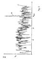
- N 100 of converter elements are accommodated with the same extension of the converter arrangement as in FIG. 2.
- their distances from one another are stochastic or noisy.
- the secondary level attenuation is almost constant over the entire angular range and is somewhat less than the fragmented grating praise 32 and 33 in FIG Grating lobe angle ⁇ itself is not as high a damping R2 as achieved in the converter arrangement according to the invention.
- the damping is comparable over the entire angular range.
- the number of converters z of the q groups is varied.
- the distance d 0.75 ⁇ ⁇ .
- the individual transducer elements in each group are at a distance of 0.75 ⁇ from each other, the groups from each other at a distance of 1.5 ⁇ 0.75 ⁇ .
- the first group 110 located on the left outer edge has only one converter element, the adjacent group 111 two, the group 112 three converter elements, the group 113 four converter elements, the group 114 five converter elements, the groups 115 and 116 six converter elements, the group 117 seven transducer elements and groups 118 and 119 each have eight transducer elements.
- the number of transducers z in the following groups have the same size symmetrically to the center 11.
- the groups with the even numbers 110, 112, ..., 128 form a sub-base 200
- the groups 111, 113, ..., 129 with odd numbers form a second sub-base 300.
- the sub-bases 200, 300 are nested one inside the other and reversed mirror-symmetrically.
- Each sub-base 200, 300 has a grid of d, which is shifted from one another by d / 2.
- the number of transducers z of the q groups are selected so that a directional characteristic according to FIG. 5 is achieved with a corresponding directional element when swiveling by the maximum swivel angle max .
- This directional characteristic is characterized by the fact that a maximum attenuation is achieved around the grating-lobe angle ⁇ and that no further periodic portions are recorded in the directional characteristic.
- the secondary levels in the area of the main lobe 30 are also particularly strongly damped. In order to obtain such a pattern of the directional characteristic, the following dimensioning instructions have been observed:
- subgroup 200 is thus in the middle 11 of the transducer arrangement. The same applies to the sub-base 300.
- FIG. 6 shows a diagram in which the standard dimension R in dB for a different number q of groups is entered over the angle Winkel.
- the sensitivities are the same if the transducer arrangement has equidistantly distributed transducer elements whose spacing is greater than half the wavelength.
- the curves r and s indicate limit values for the damping of the fragmented grating praise for the different number q of groups.
- R0 the limit value
- the number q of groups is to be dimensioned depending on the task of the entire sonar system.
Landscapes
- Measurement Of Velocity Or Position Using Acoustic Or Ultrasonic Waves (AREA)
Claims (8)
- Dispositif à transducteurs comportant une multiplicité d'éléments transducteurs pour l'émission et/ou la réception d'ondes situées dans une gamme pouvant être prédéterminée de fréquences et qui sont séparées les unes des autres par un écart supérieur à la moitié de la longueur d'onde correspondant à la fréquence maximale de la gamme de fréquences, et comportant une unité de commande de phase ou de temps de propagation pour chaque élément transducteur pour plusieurs caractéristiques directionnelles dirigées dans des directions différentes, ou une caractéristique directionnelle pivotante présentant un angle d'ouverture prédéterminé et des lobes affaiblis secondaires, caractérisé en ce que les éléments transducteurs sont disposés le long d'une ligne suivant des groupes (21, 22,23,24 ou 110,111,...,129), les éléments transducteurs à l'intérieur d'un groupe étant séparés par les mêmes distances (d), supérieures à la demi-longueur d'onde (λ), de telle sorte que les groupes sont rangées symétriquement par rapport au centre (11) du dispositif à transducteurs et que des distances limites entre des éléments transducteurs extérieurs, disposés côte-à-côte, de groupes voisins (21/22, ..., ou 110/111, 111/112, ...) sont égales à 1,5 fois (1,5d) des distances internes (d).
- Dispositif à transducteurs suivant la revendication 1, caractérisé en ce que la ligne est une droite (10).
- Dispositif à transducteurs suivant la revendication 1 ou 2, caractérisé en ce que le nombre (q) des groupes (21,22,23,24 ou 110,111,...129) pour la multiplicité N des éléments transducteurs peut être sélectionné en fonction de la distance d'affaiblissement requise entre le lobe principal (30) et les lobes secondaires divisés (31, 32).
- Dispositif à transducteurs suivant la revendication 2 ou 3, caractérisé en ce que les groupes (22/23, 21/24 ou 110/129; 111/128; ..., 119/120), qui sont disposés symétriquement par rapport au centre (11), possèdent les mêmes nombres (z) de transducteurs, que les nombres (z) de transducteurs de groupes voisins (21/22; ..., 23,24 ou 110/111,..., 119/120,...,121/122) sont choisis égaux ou différents et diminuent du centre en direction du bord du dispositif à transducteurs.
- Dispositif à transducteurs suivant la revendication 4, caractérisé en ce que les nombres (z). de transducteurs dans chaque groupe (110,...,129) sont choisis de telle sorte que les groupes (110,112,114,...,128 ou 111, 113,...,129) forment, le long des droites (10) en partant du bord et au-delà du centre (11) jusqu'à l'autre bord respectivement d'un groupe (111,113,... ou 112,114,...), en gros deux bases partielles (200,300) imbriquées l'une dans l'autre et ayant un agencement symétrique respectivement à partir du bord, et que dans chaque base partielle (200,300) il existe un décalage correspondant à la distance (d) entre les éléments transducteurs et leurs multiples et que le décalage des deux bases partielles (200,300) l'une par rapport à l'autre est décalé de la moitié de la distance (d) entre les éléments transducteurs.
- Dispositif à transducteurs suivant la revendication 5, caractérisé en ce que le nombre (z) des transducteurs des groupes (110,...,128 ou 111,...,129) sont choisis de telle sorte que pour chaque base partielle (200, 300), les sommes des distances entre le centre (11) du dispositif à transducteurs et chaque élément transducteur sont les mêmes de chaque côté.
- Dispositif à transducteurs suivant la revendication 5, caractérisé en ce que les nombres (z) des transducteurs des groupes (110,...,128 ou 111,...,129) sont choisis de telle sorte que pour chaque base partielle (200, 300), les sommes des produits des distances entre le centre (11) du dispositif à transducteurs et chaque élément transducteur, multipliées par un facteur de pondération d'amplitude, au moyen duquel un signal de réception de l'élément transducteur respectif est pondéré, sont égaux des deux côtés.
- Dispositif à transducteurs suivant l'une des revendications 1 à 7, caractérisé en ce que, dans le cas du fonctionnement impulsionnel, le nombre (q) des groupes (110,...,129) et le nombre moyen (z) de transducteurs sont choisis en fonction de la durée (Δt) des impulsions de sorte que la longueur moyenne (l) de deux groupes voisins (119/120) est multipliée par la vitesse du son (c) et est divisée par le sinus d'un angle maximum de pivotement (φmax) plus l'angle (β) du lobe du grating.
Applications Claiming Priority (2)
| Application Number | Priority Date | Filing Date | Title |
|---|---|---|---|
| DE4010502A DE4010502A1 (de) | 1990-04-02 | 1990-04-02 | Wandleranordnung |
| DE4010502 | 1990-04-02 |
Publications (3)
| Publication Number | Publication Date |
|---|---|
| EP0450191A2 EP0450191A2 (fr) | 1991-10-09 |
| EP0450191A3 EP0450191A3 (en) | 1992-01-29 |
| EP0450191B1 true EP0450191B1 (fr) | 1995-05-24 |
Family
ID=6403543
Family Applications (1)
| Application Number | Title | Priority Date | Filing Date |
|---|---|---|---|
| EP90125415A Expired - Lifetime EP0450191B1 (fr) | 1990-04-02 | 1990-12-24 | Arrangement de transducteurs |
Country Status (2)
| Country | Link |
|---|---|
| EP (1) | EP0450191B1 (fr) |
| DE (2) | DE4010502A1 (fr) |
Families Citing this family (4)
| Publication number | Priority date | Publication date | Assignee | Title |
|---|---|---|---|---|
| FR2686457B1 (fr) * | 1992-01-17 | 1994-05-20 | Thomson Csf | Antenne a balayage electronique. |
| JP2001305222A (ja) * | 2000-04-26 | 2001-10-31 | Yazaki Corp | 電子走査式超音波物体検出装置及びその方法 |
| JP2001318145A (ja) * | 2000-05-01 | 2001-11-16 | Yazaki Corp | 電子走査式超音波物体検出装置及びその方法 |
| DE102005031973B3 (de) * | 2005-07-08 | 2006-08-31 | Atlas Elektronik Gmbh | Vorrichtung zum Bestimmen der Eigengeschwindigkeit eines Wasserfahrzeugs |
Family Cites Families (2)
| Publication number | Priority date | Publication date | Assignee | Title |
|---|---|---|---|---|
| US4580141A (en) * | 1983-09-19 | 1986-04-01 | The United States Of America As Represented By The Secretary Of The Army | Linear array antenna employing the summation of subarrays |
| DE3839945C2 (de) * | 1988-11-26 | 1997-04-10 | Daimler Benz Aerospace Ag | Phasengesteuerte Gruppenantenne |
-
1990
- 1990-04-02 DE DE4010502A patent/DE4010502A1/de not_active Withdrawn
- 1990-12-24 EP EP90125415A patent/EP0450191B1/fr not_active Expired - Lifetime
- 1990-12-24 DE DE59009149T patent/DE59009149D1/de not_active Expired - Fee Related
Also Published As
| Publication number | Publication date |
|---|---|
| EP0450191A2 (fr) | 1991-10-09 |
| DE4010502A1 (de) | 1991-10-10 |
| EP0450191A3 (en) | 1992-01-29 |
| DE59009149D1 (de) | 1995-06-29 |
Similar Documents
| Publication | Publication Date | Title |
|---|---|---|
| DE60218244T2 (de) | Digitale adaptive Subarray-Strahlformung und deterministische Summen-und Differenz-Strahlformung mit Störungsauslöschung und Aufrechterhaltung des Monopulsverhältnisses | |
| US5537367A (en) | Sparse array structures | |
| DE112008000513B4 (de) | Elektronisch abtastendes Radarsystem | |
| EP3039444B1 (fr) | Capteur radar pour véhicules à moteur | |
| DE102016102241B4 (de) | Auf digitaler strahlformung basierendes auflösen von nicht-im-weg-zielen, die aufgrund von gitterkeulen in array-antennen-radars als im-weg-ziele erscheinen | |
| DE69109994T2 (de) | Mikrowellenplattenantenne, insbesondere für Dopplerradar. | |
| EP3673292B1 (fr) | Système radar d'imagerie avec un réseau de récepteurs pour la détermination de l'angle d'objets en deux dimensions par une disposition étalée des antennes de réception dans une dimension | |
| DE69715297T2 (de) | Logarithmische spiralförmige Wandleranordnung | |
| DE2825396A1 (de) | Reversible elektroakustusche wandleranordnung | |
| DE102019134304A1 (de) | Radarsystem und Verfahren zum Betreiben eines Radarsystems | |
| EP0450191B1 (fr) | Arrangement de transducteurs | |
| EP0882244B1 (fr) | Procede de formation de faisceau hertzien dans des systemes de reperage | |
| DE3330672C2 (fr) | ||
| DE102019134303A1 (de) | Radarsystem und Verfahren zum Betreiben eines Radarsystems | |
| DE2226435A1 (de) | Radiointerferometer | |
| US5329495A (en) | Passive beamformer with low side lobes | |
| WO2001069798A2 (fr) | Dispositif et procede destine a un reseau d'antennes a caracteristique panoramique commandable | |
| EP1902330B1 (fr) | Procede pour determiner la vitesse propre d'un bateau | |
| EP3082273A1 (fr) | Procédé et dispositif de réduction de signaux parasites corrélés dans des systèmes de réception multi-canaux à formation de faisceau numérique | |
| DE10153443C1 (de) | Verfahren zur passiven Ortung von schallabstrahlenden Zielen | |
| EP0263314B1 (fr) | Disposition de transducteurs | |
| DE957767C (de) | Anordnung zur elektromagnetischen Rückstrahlortung mit Frequenzmodulation | |
| DE2744985C2 (de) | Einrichtung zur Beseitigung des Schielfehlers und der Schielfehlerrate einer durch ein Radom umhüllten Richtantenne | |
| DE69318524T2 (de) | Verfahren zur Strahlungskeulenkompression in Radarantennendiagrammen | |
| DE60217750T2 (de) | Gruppenantenne und Strahlformung durch Berechnung |
Legal Events
| Date | Code | Title | Description |
|---|---|---|---|
| PUAI | Public reference made under article 153(3) epc to a published international application that has entered the european phase |
Free format text: ORIGINAL CODE: 0009012 |
|
| AK | Designated contracting states |
Kind code of ref document: A2 Designated state(s): DE FR GB IT SE |
|
| PUAL | Search report despatched |
Free format text: ORIGINAL CODE: 0009013 |
|
| AK | Designated contracting states |
Kind code of ref document: A3 Designated state(s): DE FR GB IT SE |
|
| 17P | Request for examination filed |
Effective date: 19920228 |
|
| RAP1 | Party data changed (applicant data changed or rights of an application transferred) |
Owner name: ATLAS ELEKTRONIK GMBH |
|
| 17Q | First examination report despatched |
Effective date: 19940210 |
|
| RAP1 | Party data changed (applicant data changed or rights of an application transferred) |
Owner name: STN ATLAS ELEKTRONIK GMBH |
|
| GRAA | (expected) grant |
Free format text: ORIGINAL CODE: 0009210 |
|
| AK | Designated contracting states |
Kind code of ref document: B1 Designated state(s): DE FR GB IT SE |
|
| PG25 | Lapsed in a contracting state [announced via postgrant information from national office to epo] |
Ref country code: IT Free format text: LAPSE BECAUSE OF FAILURE TO SUBMIT A TRANSLATION OF THE DESCRIPTION OR TO PAY THE FEE WITHIN THE PRE;WARNING: LAPSES OF ITALIAN PATENTS WITH EFFECTIVE DATE BEFORE 2007 MAY HAVE OCCURRED AT ANY TIME BEFORE 2007. THE CORRECT EFFECTIVE DATE MAY BE DIFFERENT FROM THE ONE RECORDED.SCRIBED TIME-LIMIT Effective date: 19950524 |
|
| REF | Corresponds to: |
Ref document number: 59009149 Country of ref document: DE Date of ref document: 19950629 |
|
| ET | Fr: translation filed | ||
| GBT | Gb: translation of ep patent filed (gb section 77(6)(a)/1977) |
Effective date: 19950615 |
|
| PG25 | Lapsed in a contracting state [announced via postgrant information from national office to epo] |
Ref country code: SE Effective date: 19950824 |
|
| PGFP | Annual fee paid to national office [announced via postgrant information from national office to epo] |
Ref country code: GB Payment date: 19951102 Year of fee payment: 6 |
|
| PGFP | Annual fee paid to national office [announced via postgrant information from national office to epo] |
Ref country code: FR Payment date: 19951117 Year of fee payment: 6 |
|
| PLBE | No opposition filed within time limit |
Free format text: ORIGINAL CODE: 0009261 |
|
| STAA | Information on the status of an ep patent application or granted ep patent |
Free format text: STATUS: NO OPPOSITION FILED WITHIN TIME LIMIT |
|
| 26N | No opposition filed | ||
| PG25 | Lapsed in a contracting state [announced via postgrant information from national office to epo] |
Ref country code: GB Effective date: 19961224 |
|
| GBPC | Gb: european patent ceased through non-payment of renewal fee |
Effective date: 19961224 |
|
| PG25 | Lapsed in a contracting state [announced via postgrant information from national office to epo] |
Ref country code: FR Effective date: 19970829 |
|
| REG | Reference to a national code |
Ref country code: FR Ref legal event code: ST |
|
| PGFP | Annual fee paid to national office [announced via postgrant information from national office to epo] |
Ref country code: DE Payment date: 19990127 Year of fee payment: 9 |
|
| PG25 | Lapsed in a contracting state [announced via postgrant information from national office to epo] |
Ref country code: DE Free format text: LAPSE BECAUSE OF NON-PAYMENT OF DUE FEES Effective date: 20001003 |