EP0450357B1 - Regelungssystem zur Rauchgaskonditionierung - Google Patents
Regelungssystem zur Rauchgaskonditionierung Download PDFInfo
- Publication number
- EP0450357B1 EP0450357B1 EP91103878A EP91103878A EP0450357B1 EP 0450357 B1 EP0450357 B1 EP 0450357B1 EP 91103878 A EP91103878 A EP 91103878A EP 91103878 A EP91103878 A EP 91103878A EP 0450357 B1 EP0450357 B1 EP 0450357B1
- Authority
- EP
- European Patent Office
- Prior art keywords
- flow rate
- conditioning agent
- power consumption
- time
- operating range
- Prior art date
- Legal status (The legal status is an assumption and is not a legal conclusion. Google has not performed a legal analysis and makes no representation as to the accuracy of the status listed.)
- Expired - Lifetime
Links
- 230000003750 conditioning effect Effects 0.000 title claims description 111
- 239000003546 flue gas Substances 0.000 title claims description 46
- UGFAIRIUMAVXCW-UHFFFAOYSA-N Carbon monoxide Chemical compound [O+]#[C-] UGFAIRIUMAVXCW-UHFFFAOYSA-N 0.000 title claims description 44
- 239000003795 chemical substances by application Substances 0.000 claims description 86
- 239000012717 electrostatic precipitator Substances 0.000 claims description 38
- AKEJUJNQAAGONA-UHFFFAOYSA-N sulfur trioxide Chemical group O=S(=O)=O AKEJUJNQAAGONA-UHFFFAOYSA-N 0.000 claims description 28
- 238000000034 method Methods 0.000 claims description 27
- 239000013618 particulate matter Substances 0.000 claims description 10
- 230000003247 decreasing effect Effects 0.000 claims description 9
- 238000005259 measurement Methods 0.000 claims description 5
- 238000005367 electrostatic precipitation Methods 0.000 claims description 4
- 239000012716 precipitator Substances 0.000 description 26
- 238000013459 approach Methods 0.000 description 24
- 239000007789 gas Substances 0.000 description 24
- 230000008859 change Effects 0.000 description 18
- 230000006870 function Effects 0.000 description 17
- 239000000567 combustion gas Substances 0.000 description 9
- 238000004364 calculation method Methods 0.000 description 8
- 239000003245 coal Substances 0.000 description 8
- 239000010881 fly ash Substances 0.000 description 8
- 230000006399 behavior Effects 0.000 description 7
- QAOWNCQODCNURD-UHFFFAOYSA-N Sulfuric acid Chemical compound OS(O)(=O)=O QAOWNCQODCNURD-UHFFFAOYSA-N 0.000 description 6
- 230000000694 effects Effects 0.000 description 6
- XLYOFNOQVPJJNP-UHFFFAOYSA-N water Substances O XLYOFNOQVPJJNP-UHFFFAOYSA-N 0.000 description 6
- NINIDFKCEFEMDL-UHFFFAOYSA-N Sulfur Chemical compound [S] NINIDFKCEFEMDL-UHFFFAOYSA-N 0.000 description 4
- 238000007792 addition Methods 0.000 description 4
- 239000002245 particle Substances 0.000 description 4
- 239000011593 sulfur Substances 0.000 description 4
- 238000004458 analytical method Methods 0.000 description 3
- 230000008901 benefit Effects 0.000 description 3
- 238000002485 combustion reaction Methods 0.000 description 3
- 230000007423 decrease Effects 0.000 description 3
- 238000010586 diagram Methods 0.000 description 3
- 238000002347 injection Methods 0.000 description 3
- 239000007924 injection Substances 0.000 description 3
- MWUXSHHQAYIFBG-UHFFFAOYSA-N nitrogen oxide Inorganic materials O=[N] MWUXSHHQAYIFBG-UHFFFAOYSA-N 0.000 description 3
- 239000007787 solid Substances 0.000 description 3
- 229910052717 sulfur Inorganic materials 0.000 description 3
- QGZKDVFQNNGYKY-UHFFFAOYSA-N Ammonia Chemical compound N QGZKDVFQNNGYKY-UHFFFAOYSA-N 0.000 description 2
- 230000001419 dependent effect Effects 0.000 description 2
- 230000005611 electricity Effects 0.000 description 2
- 238000005516 engineering process Methods 0.000 description 2
- 239000003344 environmental pollutant Substances 0.000 description 2
- 231100000719 pollutant Toxicity 0.000 description 2
- 238000011282 treatment Methods 0.000 description 2
- 238000011144 upstream manufacturing Methods 0.000 description 2
- 238000010795 Steam Flooding Methods 0.000 description 1
- 229910021529 ammonia Inorganic materials 0.000 description 1
- 230000015572 biosynthetic process Effects 0.000 description 1
- 230000001143 conditioned effect Effects 0.000 description 1
- 238000010276 construction Methods 0.000 description 1
- 238000013461 design Methods 0.000 description 1
- 230000004069 differentiation Effects 0.000 description 1
- 239000000428 dust Substances 0.000 description 1
- 230000005686 electrostatic field Effects 0.000 description 1
- 230000007613 environmental effect Effects 0.000 description 1
- 238000011156 evaluation Methods 0.000 description 1
- 239000000446 fuel Substances 0.000 description 1
- 238000010438 heat treatment Methods 0.000 description 1
- 239000007788 liquid Substances 0.000 description 1
- 239000000463 material Substances 0.000 description 1
- 230000007246 mechanism Effects 0.000 description 1
- 230000010355 oscillation Effects 0.000 description 1
- 230000001376 precipitating effect Effects 0.000 description 1
- 230000008569 process Effects 0.000 description 1
- 238000000926 separation method Methods 0.000 description 1
- 229910052815 sulfur oxide Inorganic materials 0.000 description 1
- 230000001052 transient effect Effects 0.000 description 1
Images


Classifications
-
- B—PERFORMING OPERATIONS; TRANSPORTING
- B03—SEPARATION OF SOLID MATERIALS USING LIQUIDS OR USING PNEUMATIC TABLES OR JIGS; MAGNETIC OR ELECTROSTATIC SEPARATION OF SOLID MATERIALS FROM SOLID MATERIALS OR FLUIDS; SEPARATION BY HIGH-VOLTAGE ELECTRIC FIELDS
- B03C—MAGNETIC OR ELECTROSTATIC SEPARATION OF SOLID MATERIALS FROM SOLID MATERIALS OR FLUIDS; SEPARATION BY HIGH-VOLTAGE ELECTRIC FIELDS
- B03C3/00—Separating dispersed particles from gases or vapour, e.g. air, by electrostatic effect
- B03C3/01—Pretreatment of the gases prior to electrostatic precipitation
- B03C3/013—Conditioning by chemical additives, e.g. with SO3
-
- B—PERFORMING OPERATIONS; TRANSPORTING
- B01—PHYSICAL OR CHEMICAL PROCESSES OR APPARATUS IN GENERAL
- B01D—SEPARATION
- B01D51/00—Auxiliary pretreatment of gases or vapours to be cleaned
- B01D51/10—Conditioning the gas to be cleaned
Definitions
- This invention relates to the control of particulate matter in flue gases, and, more particularly, to a control system for the addition of conditioning agents to the flue gas.
- coal In a coal-fired power plant, coal is burned to heat air, which in turn boils water to form steam. The steam drives a turbine and thence an electric generator, producing electricity. Besides heat, the burning of the coal produces gaseous pollutants such as sulfur and nitrogen oxides, and a solid particulate known as fly ash.
- gaseous pollutants such as sulfur and nitrogen oxides
- fly ash a solid particulate known as fly ash.
- Environmental protection laws mandate that the amounts of gaseous pollutants and solid particulate emitted from the power plant be maintained at acceptably low levels, and the present invention deals generally with the technology for controlling particulate emissions.
- the flue gas stream with entrained particulate is passed between electrically energized electrodes that charge the particles so that they are attracted to, and deposited upon, a collection electrode.
- the particulate may optionally be charged prior to entry into the precipitator to increase the efficiency of removal.
- the cleaned combustion gases are released to the atmosphere, and the precipitated particulate is removed from the collection electrode.
- a conditioning gas such as sulfur trioxide is injected into the combustion gas stream.
- the sulfur trioxide conditioning gas reacts with water vapor in the gas stream to produce sulfuric acid that is deposited upon the surface of the particulate.
- the sulfuric acid reduces the electrical resistance of the particulate, which is equivalent to raising the electrical conductivity of the fly ash particulate, so that the electrostatic precipitation treatment works well.
- Conditioning treatments are routinely used where the sulfur content of the coal burned in the power plant is so low that the electrical resistivity of the resulting particulate is too high to permit the electrostatic precipitators to operate with optimum collection rates.
- the amount of conditioning agent added to the flue gas should be selected to optimize the precipitator performance.
- the control procedures are performed manually, based upon the observations of the operator, or by a feedback control based upon maintaining a particular value of the power consumption of the electrostatic precipitator.
- the document EP-A-0 274 132 describes a SO3 flue gas conditioning system where a stream of flue gas is provided to an electrostatic precipitator, with a conditioning agent being added to the flue gas before it enters the electrostatic precipitator.
- the input power level to the electrostatic precipitator and the amount of conditioning agent are monitored in order to maintain the input power at a predetermined level.
- the present invention provides a method and apparatus for controlling the addition of conditioning agent to flue gas streams containing particulate matter.
- the approach utilizes measurements of system performance as the basis for feedback control of the conditioning agent flow rate. It requires no operator input, and therefore is not affected by variations in operator judgment.
- a proper amount of conditioning agent may be added to reach and maintain optimum or near-optimum electrostatic precipitator performance.
- a method for controlling the flow rate of a conditioning agent in a flue gas conditioning operation comprises the steps of providing a stream of flue gas to an electrostatic precipitator, with a conditioning agent being added to the flue gas before it enters the electrostatic precipitator; establishing a flow rate F of the conditioning agent into the flue gas as a function of time; measuring the electrostatic precipitator power consumption P as a function of time; and controlling the flow rate of the conditioning agent such that the first derivative of the power consumption as a function of the flow rate of the conditioning agent, dP/dF, is within a preselected operating range defined by numerically positive values.
- the flow rate F is expressed relative to the flow rate of the flue gas, and is typically in parts per million by volume. Thus, to determine the mass flow rate of the conditioning agent, as in pounds per unit time, it is necessary to multiply F by the flow rate of the flue gas.
- apparatus for controlling the flow rate of a conditioning agent added into a stream of a flue gas that is subsequently subjected to electrostatic precipitation to remove particulate matter from the flue gas comprises means for measuring the power consumption of the electrostatic precipitator P as a function of time; means for determining the flow rate of the conditioning agent F as a function of time; and means for controlling the flow rate of the conditioning agent such that the first derivative of the power consumption P as a function of the flow rate of the conditioning agent F is within a preselected operating range greater than zero.
- Power consumption P of the electrostatic precipitator is a good measure of the effectiveness of the conditioning process.
- the power consumption is dependent upon the amount of particulate matter being deposited upon the collection plates. Where the power consumption is low, few particles are deposited. Maximum power consumption results from a large voltage charging particles and electrical current carried through the deposited particles to the collector electrode, and thence capture of a large fraction of the particulate matter in the flue gas.
- the present invention utilizes the slope of the functional relationship as the basis for control of the conditioning agent flow rate. At flow rates of conditioning agent near or just below the possible branching point, the slope is always positive. A preselected value of the slope, termed the operating range, is selected as the control point, and the flow rate of the conditioning agent is adjusted to maintain the slope within the operating range. If the measured slope is less than the operating range, the flow rate of conditioning agent is decreased. If the measured slope is greater than the operating range, the flow rate of conditioning agent is increased.
- the present invention provides a reproducible approach for automatically controlling the flow rate of the conditioning agent to achieve near-optimal operation of the electrostatic precipitator.
- the approach provides a control system and method that is operable with existing precipitators and conditioning apparatus.
- the present invention is preferably used in conjunction with an apparatus 10 for precipitating particulate from a combustion gas stream, which is depicted in Figure 1.
- a combustion gas stream which is depicted in Figure 1.
- coal is burned by a combustor 12, and the resulting hot flue or combustion gas is passed through a boiler 14, where it heats and boils water.
- the resulting steam in a loop 16 flows to a turbine/generator set 18, where electricity for consumption is produced.
- the steam is condensed, and the water flows back through the loop 16.
- the flue gas stream leaving the boiler 14, indicated by numeral 20 cannot normally be exhausted directly to the atmosphere, because it contains the particulate or fly ash resulting from the combustion 12. If it were exhausted to the atmosphere, the fly ash would contaminate the environment. Fortunately, the fly ash can be removed from the flue gas stream 20 by electrostatic precipitator technology, if the fly ash has an acceptable electrical resistivity.
- the fly ash produced by some types of coal, particularly coal containing a low sulfur content, has too high an electrical resistance to be processed in an electrostatic precipitator, and therefore must be conditioned before entering the precipitator. It is known to inject a conditioning agent into the combustion gas stream by a conditioning apparatus 30, illustrated schematically in Figure 1.
- the conditioning apparatus 30 injects a conditioning agent (that may be a gas, a liquid, or a solid, but is preferably a gas) into the flue gas stream 20.
- the conditioning agent is preferably sulfur trioxide, but may be, for example, other gaseous oxides of sulfur, ammonia, or water vapor.
- the preferred apparatus 30 therefore includes a source 32 of the conditioning gas, and a plurality of injector nozzles 34 that extend into the flue gas stream 20 to inject the conditioning gas directly into the stream 20.
- a valve 36, or other flow control device meters the conditioning gas into the combustion gas stream 20 through the nozzles 34 at a volumetric or mass flow rate.
- a preferred source 32 is disclosed in US patent 3,993,429, and a preferred construction of the nozzles 34 is disclosed in US patent 4,179,071. The disclosures of both of these patents are incorporated herein by reference.
- the injector nozzles 34 are shown as injecting the conditioning agent at a location upstream (on the hot side) of a preheater 39.
- the injector nozzles 34 may also be located downstream (on the cold side) of the preheater 39.
- the injector nozzles 34 must, however, be upstream of the precipitator, so that the conditioning agent is injected into the gas stream before it is processed by the precipitator.
- the injected conditioning gas molecules react with the particulate in the gas stream to modify the conductivity of the particulate, or, alternatively stated, to adjust its resistivity.
- the conditioning gas reacts with the residual moisture (water vapor) in the flue gas to form sulfuric acid on the surface of the particulate, which increases the electrical conductivity of the particulate.
- the combustion gas stream 20 of flue gas flows through the preheater 39 which cools the stream 20 of flue gas by heating the stream of incoming air flowing to the combustor 12, and then to an electrostatic precipitator 40.
- the precipitator 40 may be of any of the many types commercially available and known in the art.
- the precipitator 40 includes a plurality of electrodes 42 charged with a high voltage, and grounded collector plates 44. The particulate in the gas stream 20 is charged by the electrostatic field established between the electrodes 42 and the plates 44, and is attracted to be deposited as a layer 46 upon the plates 44 for subsequent removal.
- electrostatic precipitator 40 to effect removal of particulate from the gas stream, including the voltage and current applied to the electrodes 42, the rapping of the plates 44 to cause the collected particulate to fall into hoppers, and auxiliary control and display functions are under the control of an electrostatic precipitator controller 48.
- the gas stream that leaves the electrostatic precipitator 40 is forced up an exhaust stack 50 by a blower 52, and thence into the atmosphere.
- the present invention provides a method for determining the best value for the flow rate of the conditioning agent through the valve 36 and the injectors 34, to mix with the flue gas stream 20.
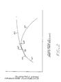
- Figure 2 illustrates the basis for the approach.
- Figure 2 is a graph of the power P in kilowatts flowing in the electrostatic precipitator 40 from the electrodes 42 to the plates 44, which can be viewed as the power consumed by the precipitator 40, as a function of the flow rate F of the preferred sulfur trioxide conditioning agent in parts per million of the gas stream 20, by volume.
- Power is defined as the product of the current and the voltage, but since the voltage may remain approximately constant during any particular operating period, current flow is an alternative acceptable measure in some cases.
- the flow rate F is the total mass flow rate of conditioning agent divided by the total mass flow rate of the gas stream 20, and is such can be viewed as a normalized flow rate.
- the power consumption of the electrostatic precipitator measures the effectiveness of the collection of particulate matter by the precipitator. Up to a point, the larger the power consumed, the more particulate matter is collected in the layer 46.
- the functional relationship shows that increasing the sulfur trioxide flow results in increased power consumption, as desired.
- a branching point 62 there may be either of two different behaviors, depending upon a number of factors, such as type of precipitator, gas flow rate, type of fuel being burned, etc.
- increasing the sulfur trioxide flow rate results in decreased power consumption.
- the first branch behavior is often observed for high gas velocities across the precipitator face, where precipitated material is blown away.
- increasing the sulfur trioxide flow rate results in increased power consumption.
- Second branch behavior is sometimes observed for low velocities of gas across the precipitator face, for example.
- the conditioning agent is introduced at a flow rate near to, but slightly below, that corresponding to a maximum point 68 in the first branch curve 64.
- a desired operating range 70 is slightly less than the maximum point 68, to avoid the inherent instability resulting from the separation between the first branch 64 and the second branch 66.
- the slope or derivative of the functional relationship between power consumption P and flow rate of conditioning agent F, dP/dF, has been selected as the basis for controlling the flow rate of the conditioning agent. Because the value of P decreases to the right of the maximum point of the first branch curve 64, the use of the functional value of P as a function of F (as distinct from the derivative) runs the risk of producing ambiguous results. Thus, attempting to control the conditioning agent flow based upon a preselected value of power consumption or upon maximizing the power consumption can lead to control system error. The derivative, however, when properly used is without ambiguity.
- the derivative dP/dF of the functional relationship between P and F, at an operating point within the operating range 70, is represented by a line 72. If the value of dP/dF is specified to be a preselected, small positive number (or, more generally, to be a small positive value within a specified operating range defined by numerically positive values of the slope, with zero considered to be within the range of positive numbers for this purpose), there is no ambiguity as to its associated flow rate F or its functional relation within the region 60 or on either branch 64 or 66.
- the derivative dP/dF is greater than the preselected operating range, then the value of F is to the left of the operating range 70, and the flow rate of conditioning agent must be increased to bring the system back to the operating point and operating range.
- the system may be operating either on the second branch 66 if the derivative is slightly less than the operating range, or on the first branch 64 if the derivative is much less than the operating range, or less than zero. In either of these cases, however, it is known with certainty that the flow rate F must be decreased to bring the system back to the desired operating range 70.
- the operating point of the first derivative dP/dF and the operating range are selected empirically for any particular power plant operation.
- the desired value for the derivative dP/dF might be 0.05 kilowatts of power per part per million of the conditioning gas.
- the operating range in this case might be selected as from zero to 0.10 kilowatts per part per million.
- the power level P may not respond instantaneously to changes in the conditioning agent flow rate F, and in fact there may be a lag time of up to several hours between a change in F and a responsive change in P.
- this phenomenon is taken into account by a delay time used in pairing F values with P values. That is, one may use the F value measured at an earlier time in conjunction with a currently measured value of P. The time difference between the taking of the F measurement and the P measurement then becomes the delay or lag time for the computation. To introduce the delay time into the computations, a chain rule derivative approach is used.
- a method for controlling the flow of a conditioning agent added to a flue gas stream prior to the flue gas stream entering an electrostatic precipitator comprises the steps of measuring a derivative dF/dt of a flow rate F of the conditioning agent into the flue gas as a function of time t, at a first time t1; measuring a derivative dP/dt of an electrostatic precipitator power consumption P as a function of time t, at a second time t2; and controlling the flow rate of the conditioning agent such that the first derivative of the power consumption as a function of the flow rate of the conditioning agent, dP/dF, is within a preselected operating range, the step of conditioning including the substeps of determining a measured value of dP/dF by dividing dP/dt by dF/dt, comparing the measured value of dP/dF with the preselected operating range, adjusting the flow rate F as necessary so as to maintain the value of dP/dF within
- a controller 80 that controls the flow rate F of the conditioning agent is illustrated in Figure 1 in relation to the other components of the system, and in detail in Figure 3.
- Four analog inputs 82 of power consumption from individual pairs of electrodes 42 and plates 44 are provided to the controller 80 from the precipitator controller 48.
- These analog inputs 82 are used in two ways. First, they are provided to a rate alarm 84 that senses whether the individual input 82 has changed status, that is, has gone out of service or entered service.
- the individual outputs of the rate alarms 84 are logically OR'd in OR function 86 to signal whether any of the individual analog inputs has changed status. If so, then a timer 88 activates a switch block 108 to output a value equal to the measured flow rate F for a pre-selected time period.
- the output of the switch block 108 is the setpoint to the controller to be described subsequently.
- the analog inputs 82 of the power consumption P are also added together at adder 90 to obtain a total instantaneous power consumption of the electrostatic precipitator.
- the adder 90 may be programmed to add together all of the analog inputs 82, as illustrated, or only some portion or grouping of the analog inputs 82. For example, it may be known from prior experience with a particular power plant that some group of analog inputs 82 is most quickly and strongly indicative of total precipitator performance, or that analog inputs corresponding to a particular region of the precipitator provide the best tracking of overall performance. In another example, if one of the precipitator power supplies has just been started up, its analog input values may reflect a transient condition, and its inclusion in the calculations might distort the results. In that case, that particular analog value could be excluded for a period of time to permit steady state operation to be achieved.
- the approach of the invention provides sufficient computational flexibility to take such information into account in developing the control parameters of the system.
- the derivative of the power P with time t, dP/dt is calculated by a differentiator 92. This differentiation takes place over a period of time, and a moving average derivative may be used. It is important to understand gross changes of power consumption as a result of changes in operating conditions and conditioning gas, not short term changes that might occur from local fluctuations. While a power plant is a large piece of apparatus and structure, it can undergo short term fluctuations. If the controller were permitted to adjust to each short term fluctuation, it would tend to oscillate widely. Instead, overall performance averaged over time periods of minutes or hours is used.
- the current measured flow rate of the conditioning agent relative to the flow rate of the gas stream, the rate F in parts per million shown at numeral 94, is obtained from measuring instrumentation in the source 32 and/or the valve 36.
- the current power consumption may be a result of a flow rate of conditioning agent that occurred some time previously, and therefore a delay 95 is provided. That is, the value of F used in a calculation may be that obtained at time t1 and the value of P that obtained at time t2. t1 and t2 may be same, or t1 may be earlier than t2.
- values of F and P are measured and stored in a memory, a running time average of each is calculated to avoid short term fluctuations, and these averages are stored. The appropriate derivatives may then be calculated, as described below.
- the delay time used in selecting values varies with the configuration of each power plant and its operating conditions, and no fixed value can be stated.
- Delay time information is developed during initial operating trials of the power plant and the controller 80. The delay time values for particular operating conditions and changes in operating conditions are then refined with continued experience, using the information stored in the manner discussed above.
- the derivative of the flow rate F of the conditioning agent with time t, dF/dt is determined by a differentiator 96 of the same general type as differentiator 92.
- the current measured value of dP/dF is found by dividing dP/dt by dF/dt at divider 98.
- the value of dP/dF is the local slope of the curve of Figure 2, and is the fundamental basis for control.
- the value of dP/dF is compared with a setpoint value, the preselected operating range 100, in a proportional integral derivative calculation 102, whose output is a measure of the degree of deviation between the measured value of dP/dF and the operating range 100.
- This output is supplied to a scaling multiplier 104.
- the output of the multiplier 104 is then supplied through the switch block 108 as the set point to a second proportional integral derivative calculation 106. (As described previously, alarm conditions cause the setpoint of 106, produced by the switch block 108, to be set equal to the measured value of flow rate for a pre-selected time period.)
- the other input to this calculation 106 is the measured value of the flow rate 94.
- the output of the calculation 106 is a signal that controls whether the valve 36 should open further to introduce more conditioning agent to the stream 20, or close down to restrict the flow of the conditioning agent. If the derivative dP/dF is smaller than the operating range, then F is decreased, and if the derivative dP/dF is greater than the operating range, F is increased.
- the amount by which F is changed may be in linear or nonlinear proportion to the value of dP/dF, or may be an externally preset constant amount.
- the particular operating range for a power plant is also determined for the plant and particular operating conditions, and no fixed value can be specified.
- the operating range of the derivative dP/dF is preferably as narrow as possible, and the absolute value of dP/dF is also as small as possible while maintaining stability of the system. Instability is judged by whether P values fluctuate between values on the first and second branches. If such fluctuations are observed, then the absolute value of the operating range is adjusted to a slightly higher value, and the observations are repeated. A stable operating range of dP/dF is eventually reached, and the controller 80 operates about that point.
- a well-defined set of system evaluations is used to determine the control parameters used in the control system of the invention for each power plant.
- the controller 80 can be implemented entirely by a digital computer (after converting analog inputs to digital form), or by dedicated circuit components, or by a combination of the two.
- the logical and mathematical manipulations of the digitized analog inputs are performed by a digital microprocessor. That is, the procedures of the preferred embodiment illustrated in relation to Figure 3 are performed by the microprocessor, in the manner described previously.
- An important advantage of implementing the functions of the controller 80 with a microprocessor is that the experience gained during operation of a power plant can be integrated into the basic operating algorithm so that the system becomes fully automatic. For example, experience gained during initial and ongoing operations can be used to adjust the control values in particular operating ranges, to minimize the time required to reach a new optimal performance after a change in power plant operating conditions such as boiler load or type of coal being used.
- the power plant output such as indicated by boiler load
- the prior experience gained from such changes performed previously is used to estimate the flow rate of conditioning agent required at the higher power output.
- the controller makes a coarse adjustment based upon the estimate, and then uses the procedures described herein to make fine adjustments to optimize the injection of conditioning agent.
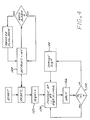
- the general control logic for the alternative approach is illustrated in Figure 4.
- the setpoint for the flow rate F is initially set at a measured value MV at block 120.
- the flow rate is then changed by an amount equal to SIGN(INCR), where "SIGN” is plus (+) or negative (-) and "INCR” is a preselected flow rate incremental change.
- the increment INCR might be selected to be 1 part conditioning agent per million parts flue gas (i.e., 1 ppm).
- the SIGN attached to INCR is determined by an analysis of the effects of a prior change, and can be plus (+), indicating an increase, or minus (-), indicating a decrease.
- the value of SIGN is determined by the control logic of Figure 4, as will be described.
- the value of "INCR”, i.e., 1 ppm, 2 ppm, etc., is initially selected based upon experience, but may subsequently be adjusted in proportion to the value of the P x measurement described hereafter. The smaller the value of INCR, the longer it will take to reach a near-optimum flow rate, but the smaller the swings about that near-optimum flow rate when it is reached.
- the sign is set positive, block 122.
- the set point SP of the flow rate F is +INCR so that the flow rate is increased by the amount of INCR, block 124.
- a value P x is calculated and tested, block 128. (The calculation of P x will be discussed below in relation to Figure 5.) If the value of P x is positive, in the next control cycle the sign remains unchanged and the set point is again changed in the same direction as in the prior control cycle.
- SIGN SIGN(INCR).
- SIGN SIGN
- the value of P x is an indicator of the location of the system in relation to the various possibilities previously indicated in relation to Figure 1. If P x is positive, the prior change in set point of the conditioning agent flow rate F was in the proper direction to move the system toward the operating range 70. If P x is negative, the prior change in set point was in the wrong direction to move the system toward the operating range 70, and the next increment must be reversed.
- a zero value of P x means that the system is within the proper operating range and at the preferred operating point. In this case of a zero value of P x , there are several options. In the preferred approach illustrated in Figure 4, SIGN is changed to establish a perturbation about the preselected operating point of F.
- SIGN could be maintained the same to drive the value of F past the preferred operating point until the system was moved to the extremum of the operating range.
- a further change in SP could simply be deferred for some period of time.
- the preferred approach establishes an oscillation about the preferred operating point, in the preselected operating range.
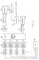
- a precipitator power level P is established using the same approach of analog inputs 82, rate alarms 84, OR function 86, and adder 90 as discussed previously.
- a flow rate F is measured in the same manner previously described, block 94.
- a change in flow rate F occurs according to block 124 of Figure 4.
- the initial flow rate before the change is made F o is measured and stored, block 140.
- the current flow rate F1 is measured, as indicated at block 94.
- the difference F1 - F0 is calculated in a subtraction 142, and then multiplied by a constant K in a multiplication 144.
- K is a constant, preselected value equal to the desired slope dP/dF at the desired operating point within the operating range 70.
- the initial precipitator power before the change is made P o is measured and stored, block 146.
- the current precipitator power P1 is measured, as indicated at block 90.
- D1 is often chosen to be the same as D2, but can be made different to account for system lag effects as discussed previously.
- the difference P1 - P o is calculated in a subtraction 148.
- the value of P x is calculated as P x - (P1 - P o ) - K (F1 - F o ) at subtraction 150. It is this value of P x that is used at block 128 of the logic of Figure 4.
- the values of power P1 and P o and the values of flow rate F1 and F o may be, and usually are, determined as averages calculated over time periods which are short compared to the delay times, but are sufficiently long to eliminate short term fluctuations.
- the present invention provides a reliable, reproducible approach to controlling the flow of a conditioning agent such as sulfur trioxide for introduction to a flue gas stream. Control is based upon the feedback of precipitator operating parameters, which are then optimized in a closed loop fashion.
Landscapes
- Chemical & Material Sciences (AREA)
- Chemical Kinetics & Catalysis (AREA)
- General Chemical & Material Sciences (AREA)
- Treating Waste Gases (AREA)
- Electrostatic Separation (AREA)
Claims (20)
- Verfahren zum Steuern der Durchflußmenge eines Konditionierungsagens in einem Rauchgaskonditionierungsvorgang, welches folgende Schritte aufweist:- Zuführen eines Rauchgasstromes an einen elektrostatischen Niederschlagsapparat, wobei dem Rauchgas ein Konditionierungsagens hinzugefügt wird, bevor es in den Niederschlagsapparat eintritt;- Einstellen einer Durchflußmenge F des Konditionierungsagens in das Rauchgas als eine Funktion der Zeit;- Messung der Leistungsaufnahme P des elektrostatischen Niederschlagsapparats als eine Funktion der Zeit;gekennzeichnet durch- Steuern der Durchflußmenge des Konditionierungsagens derart, daß die erste Ableitung dP/dF der Leistungsaufnahme P als Funktion der Durchflußmenge F des Konditionierungsagens sich innerhalb eines vorgegebenen Arbeitsbereiches befindet, der durch numerisch positive Werte bestimmt ist.
- Verfahren nach Anspruch 1 mit dem zusätzlichen Schritt, der dem Einstellschritt vorangeht,- Messen der Beziehung zwischen der Leistungsaufnahme P des elektrostatischen Niederschlagsapparates und der Durchflußmenge F des Konditionierungsagens.
- Verfahren nach Anspruch 1, dadurch gekennzeichnet, daß der Steuerungsschritt eine Durchflußmenge F einstellt derart, daß die Ableitung dP/dF eine positive Zahl ist.
- Verfahren nach Anspruch 1, dadurch gekennzeichnet, daß der Steuerungsschritt den Wert dP/dF dadurch einstellt, daß dP/dt durch dF/dt dividiert wird, wobei t die Zeit darstellt.
- Verfahren zum Steuern der Durchflußmenge eines Konditionierungsagens in einem Rauchgaskonditionierungsvorgang, um den Wirkungsgrad eines elektrostatischen Niederschlagsapparates zu erhöhen, welches folgende Schritte aufweist:- Hinzufügen einer Menge eines Konditionierungsagens mit einer Massenstrommenge F zum Rauchgasstrom bevor dieser in den elektrostatischen Niederschlagsapparat eintritt;- Messen der Leistungsaufnahmen P₂ und P₁ des elektrostatischen Niederschlagsapparates bei entsprechenden Durchflußmengen F₂ und F₁;- Bestimmen der aktuellen Steigung der Kurve der Leistungsaufnahme über der Durchflußmenge während relativ stationärer Zustände der Leistungsaufnahme über der Zeit unter Verwendung der Formel

wobei
F₂ = eine zweite Durchflußmenge
F₁ = eine erste Durchflußmenge
P₂ = gemessene Leistungsaufnahme bei F₂
P₁ = gemessene Leistungsaufnahme bei F₁;- und selektive Steuerung der Durchflußmenge F in Bezug auf die Leistungsaufnahme P derart, daß die Steigung sich innerhalb eines vorgegebenen Arbeitsbereiches befindet, der durch numerisch positive Werte bestimmt ist. - Verfahren nach Anspruch 5, dadurch gekennzeichnet, daß der Steuerungsschritt eine Durchflußmenge F einstellt, so daß die Formel eine positive Zahl ergibt.
- Verfahren nach Anspruch 1 oder 5, dadurch gekennzeichnet, daß das Konditionierungsagens Schwefeltrioxid ist.
- Verfahren nach Anspruch 7, dadurch gekennzeichnet, daß der Steuerungsschritt den Unterschritt aufweist- Erhöhen der Durchflußmenge des Konditionierungsagens, wenn die erste Ableitung größer ist als der vorgegebene Arbeitsbereich, und- Verringern der Durchflußmenge des Konditionierungsagens, wenn die erste Ableitung kleiner ist als der vorgegebene Arbeitsbereich.
- Verfahren nach Anspruch 8 mit dem zusätzlichen Schritt, der dem Steuerungsschritt vorangeht- Einsetzen einer vorgegebenen Zeitverzögerung in die Messung der Leistungsaufnahme P, die als Funktion der Zeit gemessen wird, so daß der Wert der Durchflußmenge F der im Steuerungsschritt verwendet wird, um den Wert der Zeitverzögerung vor dem Wert der Leistungsaufnahme P gemessen wird, die im Steuerungsschritt verwendet wird.
- Verfahren nach Anspruch 1, dadurch gekennzeichnet, daß der Meßschritt folgende Unterschritte aufweist:- Messen der Ableitung dF/dt der Durchflußmenge F eines Konditionierungsagens in das Rauchgas als Funktion der Zeit t zu einem ersten Zeitpunkt t₁; und- Messen der Ableitung dP/dt einer Leistungsaufnahme P eines elektrostatischen Niederschlagsapparates als Funktion der Zeit, zu einem zweiten Zeitpunkt t₂.
- Verfahren nach Anspruch 10, dadurch gekennzeichnet, daß der erste Zeitpunkt t₁ und der zweite Zeitpunkt t₂ der gleiche Zeitpunkt ist.
- Verfahren nach Anspruch 10, dadurch gekennzeichnet, daß der erste Zeitpunkt t₁ vor t₂ liegt.
- Verfahren nach Anspruch 10, dadurch gekennzeichnet, daß der Arbeitsbereich größer als Null ist.
- Verfahren nach Anspruch 10, dadurch gekennzeichnet, daß das Konditionierungsagens Schwefeltrioxid ist.
- Verfahren nach Anspruch 10, dadurch gekennzeichnet, daß der Steuerungsschritt folgende Unterschritte aufweist:- Erhöhen der Durchflußmenge des Kondtionierungsagens, wenn die erste Ableitung größer ist als der vorgegebene Arbeitsbereich, und- Verringern der Durchflußmenge des Konditionierungsagens, wenn die erste Ableitung kleiner ist als der vorgegebene Arbeitsbereich.
- Vorrichtung zum Steuern der Durchflußmenge eines Konditionierungsagens, welches einem Rauchgasstrom zugefügt wird, der anschließend einer elektrostatischen Ausfällung unterworfen wird, um Feststoffe aus dem Rauchgas zu entfernen, mit- Mitteln zum Messen der Leistungsaufnahme P des elektrostatischen Niederschlagsapparates als Funktion der Zeit;- Mitteln zum Bestimmen der Durchflußmenge F des Konditionierungsagens als Funktion der Zeit;gekennzeichnet durch- Mittel zum Steuern der Durchflußmenge F des Konditionierungsagens derart, daß die erste Ableitung dP/dF der Leistungsaufnahme P als Funktion der Durchflußrate F des Konditionierungsagens eine vorgegebene positive Zahl größer als Null ist.
- Vorrichtung nach Anspruch 16, dadurch gekennzeichnet, daß der Arbeitsbereich größer als Null ist.
- Vorrichtung nach Anspruch 16, dadurch gekennzeichnet, daß der untere Grenzwert des Arbeitsbereichs eine positive Zahl größer als Null ist.
- Vorrichtung nach Anspruch 16, dadurch gekennzeichnet, daß das Konditionierungsagens Schwefeltrioxid ist.
- Vorrichtung nach Anspruch 16, dadurch gekennzeichnet, daß die Mittel zum Steuern aufweisen- Mittel zum Erhöhen der Durchflußmenge des Kondtionierungsagens, wenn die erste Ableitung größer als der vorgegebene Arbeitsbereich ist, und- Mittel zum Verringern der Durchflußmenge des Konditionierungsagens, wenn die erste Ableitung kleiner als der vorgegebene Arbeitsbereich ist.
Applications Claiming Priority (2)
| Application Number | Priority Date | Filing Date | Title |
|---|---|---|---|
| US07/496,873 US5122162A (en) | 1990-03-19 | 1990-03-19 | Control system for flue gas conditioning |
| US496873 | 1995-06-30 |
Publications (2)
| Publication Number | Publication Date |
|---|---|
| EP0450357A1 EP0450357A1 (de) | 1991-10-09 |
| EP0450357B1 true EP0450357B1 (de) | 1995-05-17 |
Family
ID=23974545
Family Applications (1)
| Application Number | Title | Priority Date | Filing Date |
|---|---|---|---|
| EP91103878A Expired - Lifetime EP0450357B1 (de) | 1990-03-19 | 1991-03-14 | Regelungssystem zur Rauchgaskonditionierung |
Country Status (5)
| Country | Link |
|---|---|
| US (1) | US5122162A (de) |
| EP (1) | EP0450357B1 (de) |
| CA (1) | CA2038451A1 (de) |
| DE (1) | DE69109726D1 (de) |
| ES (1) | ES2073605T3 (de) |
Families Citing this family (9)
| Publication number | Priority date | Publication date | Assignee | Title |
|---|---|---|---|---|
| FI88343C (fi) * | 1989-12-28 | 1993-04-26 | Antti Johannes Niemi | Foerfarande och anordning foer beaktande av varierande volym och floede vid reglering av genomstroemningsprocesser |
| US5567226A (en) * | 1992-10-09 | 1996-10-22 | Lookman; Aziz A. | Apparatus and method for enhancing the performance of a particulate collection device |
| US5370720A (en) * | 1993-07-23 | 1994-12-06 | Welhelm Environmental Technologies, Inc. | Flue gas conditioning system |
| WO1995005343A1 (en) * | 1993-08-19 | 1995-02-23 | Ogden Projects, Inc. | Method and apparatus for reducing ammonia in combustion gases |
| US5665142A (en) * | 1994-04-12 | 1997-09-09 | Wilhelm Environmental Technologies, Inc. | Flue gas conditioning system and method using native SO2 feedstock |
| US5597403A (en) * | 1994-06-07 | 1997-01-28 | The Chemithon Corporation | Flue gas conditioning system for intermittently energized precipitation |
| US5538539A (en) * | 1995-01-20 | 1996-07-23 | Wahlco, Inc. | Catalytic sulfur trioxide flue gas conditioning |
| US5678493A (en) * | 1995-08-07 | 1997-10-21 | Wilson Eugene Kelley | Boiler flue gas conditioning system |
| US5842110A (en) * | 1996-03-11 | 1998-11-24 | University Of Central Florida | Apparatus and method for photocatalytic conditioning of fuel gas fly-ash particles |
Family Cites Families (7)
| Publication number | Priority date | Publication date | Assignee | Title |
|---|---|---|---|---|
| GB1093617A (en) * | 1964-09-01 | 1967-12-06 | Lodge Cottrell Ltd | Improvements in or relating to electro-precipitation |
| SU567496A1 (ru) * | 1971-01-14 | 1977-08-05 | Предприятие П/Я А-7229 | Способ автоматического регулировани процесса очистки газов от высокоомных пылей в электрофильтрах |
| US3993429A (en) * | 1974-10-29 | 1976-11-23 | Wahlco, Inc. | Gas conditioning means |
| DE3430016A1 (de) * | 1984-08-16 | 1986-03-20 | Metallgesellschaft Ag, 6000 Frankfurt | Optimierung der Rauchgaskonditionierung |
| US4779207A (en) * | 1987-01-06 | 1988-10-18 | The Chemithon Corporation | SO3 flue gas conditioning system |
| US4872887A (en) * | 1988-09-12 | 1989-10-10 | Electric Power Research Institute, Inc. | Method for flue gas conditioning with the decomposition products of ammonium sulfate or ammonium bisulfate |
| US4987839A (en) * | 1990-05-14 | 1991-01-29 | Wahlco, Inc. | Removal of particulate matter from combustion gas streams |
-
1990
- 1990-03-19 US US07/496,873 patent/US5122162A/en not_active Expired - Fee Related
-
1991
- 1991-03-14 EP EP91103878A patent/EP0450357B1/de not_active Expired - Lifetime
- 1991-03-14 DE DE69109726T patent/DE69109726D1/de not_active Expired - Lifetime
- 1991-03-14 ES ES91103878T patent/ES2073605T3/es not_active Expired - Lifetime
- 1991-03-18 CA CA002038451A patent/CA2038451A1/en not_active Abandoned
Also Published As
| Publication number | Publication date |
|---|---|
| EP0450357A1 (de) | 1991-10-09 |
| ES2073605T3 (es) | 1995-08-16 |
| DE69109726D1 (de) | 1995-06-22 |
| US5122162A (en) | 1992-06-16 |
| CA2038451A1 (en) | 1991-09-20 |
Similar Documents
| Publication | Publication Date | Title |
|---|---|---|
| US4987839A (en) | Removal of particulate matter from combustion gas streams | |
| EP0457225B1 (de) | Regelung der Zugabe von Konditionierungsmitteln in Abgasen | |
| US5032154A (en) | Flue gas conditioning system | |
| US5288309A (en) | Flue gas conditioning agent demand control apparatus | |
| US4624685A (en) | Method and apparatus for optimizing power consumption in an electrostatic precipitator | |
| EP0450357B1 (de) | Regelungssystem zur Rauchgaskonditionierung | |
| EP0274132B1 (de) | S03-Konditionierungssystem für Abgase | |
| McCain et al. | Results of field measurements of industrial particulate sources and electrostatic precipitator performance | |
| JP3447294B2 (ja) | 静電沈降分離装置に対する調節剤の供給の制御方法 | |
| JPH0715822B2 (ja) | 燃料電池発電プラント | |
| WO1995033568A1 (en) | Flue gas conditioning system for intermittently energized precipitation | |
| US5678493A (en) | Boiler flue gas conditioning system | |
| CN1098819C (zh) | 水泥生产设备及其废气温度的控制方法 | |
| JPS5936559A (ja) | 電気集塵機の制御方法 | |
| Reese et al. | Experience with electrostatic fly-ash collection equipment serving steam-electric generating plants | |
| Grass | Fuzzy-logic-based power control system for multifield electrostatic precipitators | |
| JP2664909B2 (ja) | ごみ焼却設備の運転方法 | |
| US11406933B1 (en) | Flue gas conditioning system controller | |
| JPH09170736A (ja) | ごみ焼却炉のごみ定量供給方法 | |
| JP3819458B2 (ja) | ごみ供給計測装置およびこれを用いた燃焼制御方法 | |
| Krigmont et al. | Development of the Intelligent Flue Gas Conditioning Injection Rate Control | |
| KR100194446B1 (ko) | 쓰레기소각로의 연소제어방법 및 그 장치 | |
| RU2045091C1 (ru) | Устройство управления процессом очистки газа в электрофильтре | |
| JP3705042B2 (ja) | 排煙処理システム | |
| Plaks | Fabric filtration with integral particle charging and collection in a combined electric and flow field: Part II. Development and verification of the mathematical engineering design model |
Legal Events
| Date | Code | Title | Description |
|---|---|---|---|
| PUAI | Public reference made under article 153(3) epc to a published international application that has entered the european phase |
Free format text: ORIGINAL CODE: 0009012 |
|
| AK | Designated contracting states |
Kind code of ref document: A1 Designated state(s): DE ES FR GB IT |
|
| 17P | Request for examination filed |
Effective date: 19920407 |
|
| 17Q | First examination report despatched |
Effective date: 19930621 |
|
| GRAA | (expected) grant |
Free format text: ORIGINAL CODE: 0009210 |
|
| AK | Designated contracting states |
Kind code of ref document: B1 Designated state(s): DE ES FR GB IT |
|
| PG25 | Lapsed in a contracting state [announced via postgrant information from national office to epo] |
Ref country code: IT Free format text: LAPSE BECAUSE OF FAILURE TO SUBMIT A TRANSLATION OF THE DESCRIPTION OR TO PAY THE FEE WITHIN THE PRE;WARNING: LAPSES OF ITALIAN PATENTS WITH EFFECTIVE DATE BEFORE 2007 MAY HAVE OCCURRED AT ANY TIME BEFORE 2007. THE CORRECT EFFECTIVE DATE MAY BE DIFFERENT FROM THE ONE RECORDED.SCRIBED TIME-LIMIT Effective date: 19950517 Ref country code: FR Effective date: 19950517 |
|
| REF | Corresponds to: |
Ref document number: 69109726 Country of ref document: DE Date of ref document: 19950622 |
|
| REG | Reference to a national code |
Ref country code: ES Ref legal event code: FG2A Ref document number: 2073605 Country of ref document: ES Kind code of ref document: T3 |
|
| PG25 | Lapsed in a contracting state [announced via postgrant information from national office to epo] |
Ref country code: DE Effective date: 19950818 |
|
| EN | Fr: translation not filed | ||
| PG25 | Lapsed in a contracting state [announced via postgrant information from national office to epo] |
Ref country code: GB Effective date: 19960314 |
|
| PLBE | No opposition filed within time limit |
Free format text: ORIGINAL CODE: 0009261 |
|
| STAA | Information on the status of an ep patent application or granted ep patent |
Free format text: STATUS: NO OPPOSITION FILED WITHIN TIME LIMIT |
|
| 26N | No opposition filed | ||
| GBPC | Gb: european patent ceased through non-payment of renewal fee |
Effective date: 19960314 |
|
| PGFP | Annual fee paid to national office [announced via postgrant information from national office to epo] |
Ref country code: ES Payment date: 19980323 Year of fee payment: 8 |
|
| PG25 | Lapsed in a contracting state [announced via postgrant information from national office to epo] |
Ref country code: ES Free format text: LAPSE BECAUSE OF NON-PAYMENT OF DUE FEES Effective date: 19990315 |
|
| REG | Reference to a national code |
Ref country code: ES Ref legal event code: FD2A Effective date: 20010503 |