EP0450402A2 - Imprimante avec un dispositif pour éliminer les charges statiques et pour compenser le relâchement du ruban encreur - Google Patents
Imprimante avec un dispositif pour éliminer les charges statiques et pour compenser le relâchement du ruban encreur Download PDFInfo
- Publication number
- EP0450402A2 EP0450402A2 EP91104339A EP91104339A EP0450402A2 EP 0450402 A2 EP0450402 A2 EP 0450402A2 EP 91104339 A EP91104339 A EP 91104339A EP 91104339 A EP91104339 A EP 91104339A EP 0450402 A2 EP0450402 A2 EP 0450402A2
- Authority
- EP
- European Patent Office
- Prior art keywords
- printer
- ink ribbon
- paper
- accordance
- reel
- Prior art date
- Legal status (The legal status is an assumption and is not a legal conclusion. Google has not performed a legal analysis and makes no representation as to the accuracy of the status listed.)
- Withdrawn
Links
- 230000003068 static effect Effects 0.000 title claims abstract description 26
- 230000005611 electricity Effects 0.000 title claims abstract description 12
- 238000001514 detection method Methods 0.000 claims description 15
- 239000004020 conductor Substances 0.000 claims description 2
- 230000000452 restraining effect Effects 0.000 claims description 2
- 230000000694 effects Effects 0.000 description 5
- 238000010438 heat treatment Methods 0.000 description 3
- 230000003287 optical effect Effects 0.000 description 2
- 229920002799 BoPET Polymers 0.000 description 1
- 239000003575 carbonaceous material Substances 0.000 description 1
- 238000010276 construction Methods 0.000 description 1
- 238000007599 discharging Methods 0.000 description 1
- 230000008030 elimination Effects 0.000 description 1
- 238000003379 elimination reaction Methods 0.000 description 1
- 239000000463 material Substances 0.000 description 1
- 239000007769 metal material Substances 0.000 description 1
- 238000012986 modification Methods 0.000 description 1
- 230000004048 modification Effects 0.000 description 1
- 238000004080 punching Methods 0.000 description 1
- 229910001220 stainless steel Inorganic materials 0.000 description 1
- 239000010935 stainless steel Substances 0.000 description 1
Images


Classifications
-
- B—PERFORMING OPERATIONS; TRANSPORTING
- B41—PRINTING; LINING MACHINES; TYPEWRITERS; STAMPS
- B41J—TYPEWRITERS; SELECTIVE PRINTING MECHANISMS, i.e. MECHANISMS PRINTING OTHERWISE THAN FROM A FORME; CORRECTION OF TYPOGRAPHICAL ERRORS
- B41J29/00—Details of, or accessories for, typewriters or selective printing mechanisms not otherwise provided for
-
- B—PERFORMING OPERATIONS; TRANSPORTING
- B41—PRINTING; LINING MACHINES; TYPEWRITERS; STAMPS
- B41J—TYPEWRITERS; SELECTIVE PRINTING MECHANISMS, i.e. MECHANISMS PRINTING OTHERWISE THAN FROM A FORME; CORRECTION OF TYPOGRAPHICAL ERRORS
- B41J33/00—Apparatus or arrangements for feeding ink ribbons or like character-size impression-transfer material
- B41J33/14—Ribbon-feed devices or mechanisms
- B41J33/52—Braking devices therefor
Definitions
- the present invention relates to a printer which is provided in copying machines, facsimiles, printing equipment, and the like, and more particularly to a printer which performs printing by abutting a printer head against a paper behind an ink ribbon while allowing the paper to pass between the ink ribbon and a platen roller and which moves said printer head backward when not performing printing.
- Fig. 1 shows the printer when not performing printing.
- members such as an ink ribbon 241, a rotatable thermal head 205, a supply reel 243 and a take-up reel 244.
- Fig. 2 is a view of the ink ribbon cassette 204 when the printer is performing printing.
- a paper P has been supplied onto a platen roller 290, while the thermal head 205 has rotated downward to cause the ink ribbon 241 to project beyond the cassette 204, thereby pressing the ink ribbon 241 against the paper P.
- a heating element of the thermal head 205 is energized to effect printing.
- the thermal head 205 is moved upward, and the ink ribbon 241 having a slack is taken up by rotating the take-up reel 244 to eliminate the slack, thereby preparing the printing for the next paper P.
- the present invention is a printer which performs printing by abutting a printer head against a paper behind an ink ribbon while allowing the paper to pass between the ink ribbon and a platen roller and which moves said printer head backward when not performing printing, wherein static eliminator means for eliminating a static electricity developing on the ink ribbon or the paper is located near the place where the ink ribbon is in contact with the paper.
- the present invention is a printer which performs printing by abutting a printer head against a paper behind an ink ribbon while allowing the paper to pass between said ink ribbon and a platen roller and which moves the printer head backward when not performing printing, comprising; start-possibility detection means for detecting the start-possibility of the operation of the printer assembly, a take-up reel for taking up the ink ribbon, reel drive means for driving the take-up reel, and control means for driving the reel drive means based on the result detected by the start-possibility detection means to allow the reel to take up the ink ribbon.
- Fig. 5 is a schematic side view showing a condition that a printer as one embodiment of the present invention is used in a copying machine, where in a housing 1 as a body of the copying machine are provided an optical system 11 for forming an electrostatic latent image corresponding to a manuscript image on a photosensitive material 12a, an image processing section 12 for developing said electrostatic latent image to a toner image and transferring the toner image onto a paper supplied from a manual paper-feeding section 14, a paper-feeding cassette 15a or a paper-feeding cassette 15b, a fixing device 17 for heating and fixing the image on the copying paper, a printer 2 , a punching device 18 , and a paper conveying section 13 to convey a paper to a discharge tray 19.
- an optical system 11 for forming an electrostatic latent image corresponding to a manuscript image on a photosensitive material 12a
- an image processing section 12 for developing said electrostatic latent image to a toner image and transferring the toner image onto a paper supplied
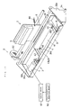
- Fig. 6 is a schematic perspective view of the printer 2
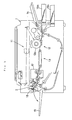
- Fig. 7 is a schematic sectional view of the inside of the copying machine showing mainly the printer 2.
- the printer 2 has a casing 3, an ink ribbon cassette 4 which is mounted removably to the casing 3 and houses a belt-like ink ribbon 41 described later, and a head supporting member 6 which is mounted rotatably to the casing 3 and supports a thermal head 5 as an example of printer heads.
- the supporting member 6 is fixed to a spindle 61, and is rotatable through an operating strip 86 mounted on one end of the spindle 61 by the rotation of a cam 82.
- the casing 3 is equipped with a box 31 whose top side is released, and side plates 32a and 32b which are fixedly secured to the both ends of the box 31.
- the side plates 32a and 32b have a substantially triangular shape, and are mounted by a spindle 34 at the lower end thereof directly or indirectly to the housing 1 of the copying machine assembly.
- the casing 3 is pivotally moved with the spindle 34 as a center.
- the ink ribbon cassette 4 is equipped with the ink ribbon 41, a body 42, and a supply reel 43 and a take-up reel the both of which are mounted parallel to the body 42, so that the ink ribbon 41 supplied from the supply reel 43 is taken up by the take-up reel 44.
- An opening 42b is formed in a bottom wall 49 of the cassette, and a bottom plate 31a of the casing 3 has an opening 33. Said print head 5 and part of the ink ribbon 41 can project through the openings 42a and 33 beyond the cassette, thereby abutting against a paper P on a platen roller 90.
- ink ribbon cassette 4 In the box 31 of the casing 3 are provided said ink ribbon cassette 4, drive means 7 for driving the take-up reel 44 of the ink ribbon cassette 4 to allow the reel to take up the ink ribbon 41, and a lock member 9 for holding a condition that the ink ribbon cassette 4 is mounted to the casing 3.
- the thermal head 5 heats a plurality of micro resistors by being energized, forming a print pattern on the paper P.
- the thermal head 5 can be raised by a spring 88 mounted to the housing of the fixing device 17.
- Fig. 8 is a perspective view showing a condition that the ink ribbon cassette 4 is removed from the box 31 of the casing 3.
- Static eliminator means 200 is mounted to the front (based on the conveyance direction of the paper P, and in the lower left direction on Fig. 8) edge of said opening 33 in the bottom plate 31a of said casing 3.
- the mounting position of the static eliminator means 200 is not particularly limited to the position of the embodiment shown, provided that the mounting position is near the place where said ink ribbon 41 is in contact with said paper P.
- the position may be beneath the paper P.
- the static eliminator means 200 may be any means utilizing an electrically-conductive material capable of eliminating static electricity such as metal material including SUS-based stainless steel, and carbon-based material.
- the shape of the means may be an arbitrary shape such as plate and comb, without being limited to brush shown in the embodiment.
- the paper P after having been fixed by fixing rollers 171 and 172 of the fixing device 17, is adapted to be fed in such a manner that it passes through conveyance rollers 100 and 101, passes over the platen roller 90, and is discharged from a discharge guide 102 to the outside of the copying machine.
- the thermal head 5 is housed in the ink ribbon cassette 4.
- the ink ribbon 41 is also housed in the ink ribbon cassette 4 after having been taken up by the take-up reel 44.
- the paper P When the paper P is supplied after having been transferred and fixed , as shown in Fig. 9, the paper P brings down a limit switch 17b at the exit of the fixing device 17, and is fed through the conveyance rollers 100 and 101 onto the platen roller 90. Based on a signal from the limit switch 17b, discharge rollers 48 and the platen roller 90 reduce the conveyance speed of the paper P to an extent that the printer can perform printing.
- the thermal head 5 is rotated downward through the operating strip 86 and the support member 6 by the rotation of the cam 82.
- the ink ribbon 41 is pulled downward accordingly, as shown in Fig. 9. Then, the ink ribbon 41 is pressed through the paper P against the platen roller 90 by the force of the thermal head 5.
- the thermal head 5 is energized to effect printing. Then, the paper P and the ink ribbon 41 thus pressed leave the place of the platen roller 90. At that time, even if a static electricity develops, the static electricity will be eliminated through the brush of the static eliminator 200 which is located near the contact place. Accordingly, even if a static electricity develops, it is immediately eliminated, whereby the paper P and the ink ribbon 41 are immediately separated from each other, and the ink ribbon 41 is taken up by the take-up reel 44, without such a misgiving that the paper P and the ink ribbon 41 are discharged while adhering to each other because of the action of the static electricity. The paper P is also smoothly discharged.
- the brush of the static eliminator 200 can eliminate sufficiently the static electricity because the brush is located near the ribbon or the paper. Where the brush is in directly contact with them, in addition to the effect of static elimination, the brush can prevent physically the paper P from floating or the ink ribbon 41 from being pulled by the paper P.
- the ink ribbon and the printer head of a printer according to the present invention may be of an arbitrary type such as impact type, without being limited to heat transfer type.
- the printer according to the present invention can be applied to any printer of facsimiles, computer printers and the like, without being limited to copying machines.
- the printer according to the present invention is equipped with static eliminator means to eliminate static electricity, whereby an ink ribbon and a paper are separated smoothly from each other. Accordingly, the printer can prevent such an inconvenience that an ink ribbon is pulled toward the discharging exit while adhering to a paper.
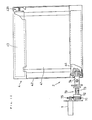
- Fig. 10 is a schematic sectional view showing the inside of a copying machine mainly concerning the printer 2
- Fig. 11 is a perspective view of the printer 2.
- the printer 2 is similar in construction to that described in Fig. 6. That is, the numeral 92 indicates start-possibility detection means for detecting the start-possibility of the operation of the printer assembly.
- the means 92 is such that it detects the on/off of a main power switch of the copying machine, or detects the on/off of a safety switch.
- the safety switch is such that it detects the open/close condition of the front cover plate which is opened if paper clogging occurs, or the open/close condition of the discharge cover plate on the discharge side of the copying machine, and a condition that an optical system such as reflecting mirrors and lenses is rotated upward beyond and pulled out of the upper part of the copying machine.
- the start-possibility detection means 92 is usually implemented by utilizing a microcomputer and sensor.
- the numeral 91 indicates control means for controlling the drive means 7 to rotate the take-up reel 44 based on a signal from the start-possibility detection means 92.
- a gear 75 is mounted to the motor shaft of the drive means 7, while a connecting shaft 74 is mounted at one end of the take-up reel 44, and a torque limiter 79 is connected between the connecting shaft 74 and said gear 75.
- the torque limiter 79 is equipped with a disk 72 urged by a spring 73 and with a friction gear 71 adhering to the disk 72 and engaged with the gear 75.
- the disk 72 is always pressed against the friction gear 71 by the spring 73, so that the disk 72 rotates following the rotation of the friction gear 71 by the friction force.
- a rotation torque is transmitted from the drive means 7 through the gear 75, the friction gear 71, the disk 72 and the connecting shaft 74 to the take-up reel 44.
- the disk 72 and the friction gear 71 begin to slide to cause the rotation torque of the drive means 7 not to be transmitted to the take-up reel 44, whereby the gear 75 rotates idly and the take-up reel 44 fails to rotate.
- the supply reel 43 is rotatably supported in a condition that it is pressed against the ink ribbon body 42 with a proper force by a spring 431 as an example of restraint means for restraining the rotation of the reel. Accordingly, in a condition that the take-up reel 44 stretches fully the ink ribbon 41 after having taken up the loosened ribbon, when the supply reel 43 begins to rotate by being pulled by the ink ribbon 41, said pressing force causes a counter torque against the take-up reel 44, whereby the drive means 7 begins to rotate idly and the take-up reel 44 takes up no more ink ribbon 41.
- the thermal head 5 heats a plurality of microresistors by being energized, thereby forming a print pattern on the paper P.
- the thermal head 5, as shown in Fig. 10, can be raised by the spring 88 mounted to the fixing device 17.
- the head may be arranged in a manner to be always urged upward and raised by the spring 88 mounted on the shaft member located in the housing 1 of the copying machine assembly.
- the paper after having been fixed by the fixing rollers 171 and 172 of the fixing device 17, is adapted to be fed in such a manner that it passes through the conveyance rollers 100 and 101, passes over the platen roller 90, and is discharged from the discharge guide 102 to the outside of the copying machine.
- the thermal head 5 is housed in the ink ribbon cassette 4.
- the ink ribbon 41 is also housed in the ink ribbon cassette 4 after having been taken up by the take-up reel 44.
- the paper P When the paper P is supplied after having been transferred and fixed during printing, as shown in Fig. 13, the paper P brings down the limit switch 17b at the exit of the fixing device 17, and is fed through the conveyance rollers 100 and 101 onto the platen roller 90. Based on a signal from the limit switch 17b, discharge rollers 48 and the platen roller 90 reduce the conveyance speed of the paper P to an extent that the printer 2 can perform printing.
- the thermal head 5 is rotated downward through the operating strip 86 and the support member 6 by the rotation of the cam 82.
- the ink ribbon 41 is pulled downward accordingly, as shown in Fig. Then, the ink ribbon 41 is pressed through the paper P against the platen roller 90 by the force of the thermal head 5. In that condition, the thermal head 5 is energized to effect printing. Then, the paper P and the ink ribbon 41 thus pressed leave the place of the platen roller 90.
- the thermal head 5 is moved upward by the urging force of the spring 88 with the rotation of the cam 82.
- the ink ribbon 41 remains slack temporarily as shown in Fig. 14.
- the take-up slack of the ink ribbon 41 is usually eliminated by rotating the take-up reel 44 with the drive means 7 driven.
- the initialization of a microcomputer is to be checked as shown in the flowchart of Fig. 15 (step S1). Then, the start-possibility detection means 92 checks that the main power switch has been turned on (step S2).
- the means 92 checks that the safety switch has been turned on (step S3).
- the start-possibility detection means 92 detects such operation, and following such detection, the control means 91 drives the drive means 7, whereby the take-up reel 44 is rotated to cause the slack of the ink ribbon 41 to be eliminated (step S4).
- the duration of the rotation is set to a time during which the slack may be sufficiently eliminated, for example, 0.8 second (step S5). If the switch is turned off again before the time of 0.8 second lapses (steps S5 and S6), the drive means 7 is to be turned off (step S7). Then, the check operation is to be returned to step S2.
- step S8 Concluding that the ink ribbon 41 has been sufficiently taken up when the time of 0.8 second thus lapsed, the drive means 7 is to be stopped (step S8). There is no misgiving about the development of over take-up because, if it develops, the drive means 7 will rotate idly by the action of the torque limiter 79 as described above.
- the ink ribbon and the printer head of a printer according to the present invention may be of an arbitrary type such as impact type, without being limited to heat transfer type.
- the printer according to the present invention can be applied to any printer of facsimiles, computer printers and the like, without being limited to copying machines.
- the printer according to the present invention is equipped with start-possibility detection means for detecting the start-possibility of the operation of the printer assembly, and based on the detection, the slack of an ink ribbon can be surely eliminated, thereby providing an advantage that, even if the printer assembly stops in a condition that the ink ribbon slacks, no ink ribbon will be damaged and no paper be stained when the operation is started again.
Landscapes
- Impression-Transfer Materials And Handling Thereof (AREA)
- Electronic Switches (AREA)
Applications Claiming Priority (4)
| Application Number | Priority Date | Filing Date | Title |
|---|---|---|---|
| JP71044/90 | 1990-03-20 | ||
| JP2071046A JP2777453B2 (ja) | 1990-03-20 | 1990-03-20 | プリンタ |
| JP71046/90 | 1990-03-20 | ||
| JP2071044A JP2656989B2 (ja) | 1990-03-20 | 1990-03-20 | プリンタ装置 |
Publications (2)
| Publication Number | Publication Date |
|---|---|
| EP0450402A2 true EP0450402A2 (fr) | 1991-10-09 |
| EP0450402A3 EP0450402A3 (en) | 1992-01-22 |
Family
ID=26412166
Family Applications (1)
| Application Number | Title | Priority Date | Filing Date |
|---|---|---|---|
| EP19910104339 Withdrawn EP0450402A3 (en) | 1990-03-20 | 1991-03-20 | Printer with a static electricity eliminator and a taking-up means for an ink ribbon slack |
Country Status (1)
| Country | Link |
|---|---|
| EP (1) | EP0450402A3 (fr) |
Cited By (5)
| Publication number | Priority date | Publication date | Assignee | Title |
|---|---|---|---|---|
| US5431504A (en) * | 1993-01-14 | 1995-07-11 | Esselte Dymo N.V. | Printing apparatus with cassette |
| EP0778135A3 (fr) * | 1995-12-08 | 1997-10-22 | Nec Corp | Dispositif d'enregistrement électrostatique à jet d'encre |
| EP0679528A3 (fr) * | 1994-04-30 | 1997-12-10 | Casio Computer Co., Ltd. | Dérouleur pour dérouler une feuille en forme de ruban |
| EP1260376A3 (fr) * | 2001-05-23 | 2003-11-12 | Isermatic Systemes | Procédé et dispositif d'impression en couleurs d'un support par transfert thermique |
| CN119610907A (zh) * | 2025-02-13 | 2025-03-14 | 珠海恒盛条码设备有限公司 | 一种新型的标签打印机 |
Family Cites Families (6)
| Publication number | Priority date | Publication date | Assignee | Title |
|---|---|---|---|---|
| DE2517766C3 (de) * | 1975-04-18 | 1982-01-07 | Mannesmann AG, 4000 Düsseldorf | Schutzschaltung für einen Matrixdrucker |
| US4494166A (en) * | 1982-09-21 | 1985-01-15 | Xerox Corporation | Printing machine with static elimination system |
| US4706320A (en) * | 1985-12-04 | 1987-11-17 | Xerox Corporation | Electrostatic charging and cleaning brushes |
| DE3603807C1 (de) * | 1986-02-07 | 1987-07-30 | Triumph Adler Ag | Verfahren und Schaltungsanordnung zum Schutz von Schreib- oder aehnlichen Bueromaschinen vor den Folgen von elektrostatischen Entladungen |
| JPH0274378A (ja) * | 1988-09-09 | 1990-03-14 | Sony Corp | リボンカートリッジ |
| JPH0719805Y2 (ja) * | 1989-02-08 | 1995-05-10 | ブラザー工業株式会社 | 印字装置 |
-
1991
- 1991-03-20 EP EP19910104339 patent/EP0450402A3/en not_active Withdrawn
Cited By (8)
| Publication number | Priority date | Publication date | Assignee | Title |
|---|---|---|---|---|
| US5431504A (en) * | 1993-01-14 | 1995-07-11 | Esselte Dymo N.V. | Printing apparatus with cassette |
| AU667412B2 (en) * | 1993-01-14 | 1996-03-21 | Esselte Dymo N.V. | Printing apparatus with cassette |
| EP0679528A3 (fr) * | 1994-04-30 | 1997-12-10 | Casio Computer Co., Ltd. | Dérouleur pour dérouler une feuille en forme de ruban |
| CN1059872C (zh) * | 1994-04-30 | 2000-12-27 | 卡西欧计算机公司 | 磁带式带状件的开卷装置 |
| EP0778135A3 (fr) * | 1995-12-08 | 1997-10-22 | Nec Corp | Dispositif d'enregistrement électrostatique à jet d'encre |
| EP1260376A3 (fr) * | 2001-05-23 | 2003-11-12 | Isermatic Systemes | Procédé et dispositif d'impression en couleurs d'un support par transfert thermique |
| CN119610907A (zh) * | 2025-02-13 | 2025-03-14 | 珠海恒盛条码设备有限公司 | 一种新型的标签打印机 |
| CN119610907B (zh) * | 2025-02-13 | 2026-03-24 | 珠海恒盛条码设备有限公司 | 一种标签打印机 |
Also Published As
| Publication number | Publication date |
|---|---|
| EP0450402A3 (en) | 1992-01-22 |
Similar Documents
| Publication | Publication Date | Title |
|---|---|---|
| US5038173A (en) | Replaceable unit determination mechanism | |
| EP0362842B1 (fr) | Appareil d'enregistrement électrophotographique | |
| US5432593A (en) | Sheet overheat prevention mechanism for fixing device | |
| EP2047996B1 (fr) | Unité de nettoyage et imprimante | |
| US5280224A (en) | Process cartridge drive mechanism and image forming apparatus | |
| EP0450402A2 (fr) | Imprimante avec un dispositif pour éliminer les charges statiques et pour compenser le relâchement du ruban encreur | |
| JPH0711070Y2 (ja) | 排紙装置 | |
| US5493318A (en) | Continuous form positioning device with control of rollers in response to a tip sensor | |
| EP3858625B1 (fr) | Appareil d'impression | |
| US5847747A (en) | Tractor unit | |
| JP2003341889A (ja) | 記録紙ロール用給紙マガジン | |
| JPS62211263A (ja) | 用紙搬送装置 | |
| JP2656989B2 (ja) | プリンタ装置 | |
| JPH0663538U (ja) | 画像形成装置 | |
| JPH0512184Y2 (fr) | ||
| JP2777453B2 (ja) | プリンタ | |
| JPH06143722A (ja) | 回転検出装置及び記録装置 | |
| JPH08211756A (ja) | 後段転写コルゲータ | |
| JPH0440204Y2 (fr) | ||
| JPH0376676A (ja) | 画像形成装置 | |
| JPH0887201A (ja) | 用紙厚検出装置及び印刷装置 | |
| JP2734996B2 (ja) | ファクシミリ装置 | |
| JP3154583B2 (ja) | プリンタの安全装置 | |
| JP2744686B2 (ja) | 画像形成装置 | |
| JP2004233823A (ja) | 画像形成装置 |
Legal Events
| Date | Code | Title | Description |
|---|---|---|---|
| PUAI | Public reference made under article 153(3) epc to a published international application that has entered the european phase |
Free format text: ORIGINAL CODE: 0009012 |
|
| AK | Designated contracting states |
Kind code of ref document: A2 Designated state(s): DE FR GB NL |
|
| PUAL | Search report despatched |
Free format text: ORIGINAL CODE: 0009013 |
|
| AK | Designated contracting states |
Kind code of ref document: A3 Designated state(s): DE FR GB NL |
|
| 17P | Request for examination filed |
Effective date: 19920709 |
|
| 17Q | First examination report despatched |
Effective date: 19930426 |
|
| STAA | Information on the status of an ep patent application or granted ep patent |
Free format text: STATUS: THE APPLICATION IS DEEMED TO BE WITHDRAWN |
|
| 18D | Application deemed to be withdrawn |
Effective date: 19930908 |