EP0450524A2 - Système de transmission optique avec un amplificateur à fibre optique - Google Patents
Système de transmission optique avec un amplificateur à fibre optique Download PDFInfo
- Publication number
- EP0450524A2 EP0450524A2 EP19910105045 EP91105045A EP0450524A2 EP 0450524 A2 EP0450524 A2 EP 0450524A2 EP 19910105045 EP19910105045 EP 19910105045 EP 91105045 A EP91105045 A EP 91105045A EP 0450524 A2 EP0450524 A2 EP 0450524A2
- Authority
- EP
- European Patent Office
- Prior art keywords
- optical signal
- fiber
- connection
- pump light
- coupler
- Prior art date
- Legal status (The legal status is an assumption and is not a legal conclusion. Google has not performed a legal analysis and makes no representation as to the accuracy of the status listed.)
- Withdrawn
Links
- 230000003287 optical effect Effects 0.000 title claims abstract description 49
- 239000000835 fiber Substances 0.000 title claims abstract description 27
- 230000005540 biological transmission Effects 0.000 title claims abstract description 17
- 230000008878 coupling Effects 0.000 claims abstract description 7
- 238000010168 coupling process Methods 0.000 claims abstract description 7
- 238000005859 coupling reaction Methods 0.000 claims abstract description 7
- 239000012783 reinforcing fiber Substances 0.000 claims abstract 2
- 239000013307 optical fiber Substances 0.000 abstract description 6
- 230000003321 amplification Effects 0.000 description 1
- 238000003199 nucleic acid amplification method Methods 0.000 description 1
Images

Classifications
-
- H—ELECTRICITY
- H04—ELECTRIC COMMUNICATION TECHNIQUE
- H04B—TRANSMISSION
- H04B10/00—Transmission systems employing electromagnetic waves other than radio-waves, e.g. infrared, visible or ultraviolet light, or employing corpuscular radiation, e.g. quantum communication
- H04B10/29—Repeaters
- H04B10/291—Repeaters in which processing or amplification is carried out without conversion of the main signal from optical form
-
- H—ELECTRICITY
- H04—ELECTRIC COMMUNICATION TECHNIQUE
- H04B—TRANSMISSION
- H04B10/00—Transmission systems employing electromagnetic waves other than radio-waves, e.g. infrared, visible or ultraviolet light, or employing corpuscular radiation, e.g. quantum communication
- H04B10/07—Arrangements for monitoring or testing transmission systems; Arrangements for fault measurement of transmission systems
- H04B10/075—Arrangements for monitoring or testing transmission systems; Arrangements for fault measurement of transmission systems using an in-service signal
- H04B10/077—Arrangements for monitoring or testing transmission systems; Arrangements for fault measurement of transmission systems using an in-service signal using a supervisory or additional signal
-
- H—ELECTRICITY
- H04—ELECTRIC COMMUNICATION TECHNIQUE
- H04B—TRANSMISSION
- H04B10/00—Transmission systems employing electromagnetic waves other than radio-waves, e.g. infrared, visible or ultraviolet light, or employing corpuscular radiation, e.g. quantum communication
- H04B10/29—Repeaters
- H04B10/291—Repeaters in which processing or amplification is carried out without conversion of the main signal from optical form
- H04B10/2912—Repeaters in which processing or amplification is carried out without conversion of the main signal from optical form characterised by the medium used for amplification or processing
-
- H—ELECTRICITY
- H04—ELECTRIC COMMUNICATION TECHNIQUE
- H04B—TRANSMISSION
- H04B2210/00—Indexing scheme relating to optical transmission systems
- H04B2210/07—Monitoring an optical transmission system using a supervisory signal
- H04B2210/078—Monitoring an optical transmission system using a supervisory signal using a separate wavelength
Definitions
- the invention relates to a system for transmitting an optical signal, as described in the preamble of claim 1.
- the light from the pump light source is coupled into the Er3+-doped fiber piece via a coupler, which is arranged in front of the amplifying fiber piece based on the direction of transmission of the optical signal to be amplified.
- the coupler coupling the pump light into the amplifying fiber piece is located behind the fiber piece, based on the direction of transmission of the signal to be amplified.
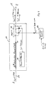
- FIG. 1 shows a transmission system with which an optical signal is to be transmitted from a point A to a point B.
- an optical transmitter not shown
- an optical receiver not shown
- the optical signal to be transmitted from A to B has a wavelength ⁇ 1 of 1540 nm.
- a monomode optical fiber 15 is used as the transmission path, which has sufficiently good transmission properties at the wavelength ⁇ 1.
- the system according to FIG. 1 also contains a fiber optic amplifier 10, which consists of an Er3+-doped fiber piece 11, a wavelength-selective fiber optic coupler 12 and a pump light source 13.
- the coupler 12 has four connections 1 to 4. Its connector 1 is connected to the optical fiber 15 coming from the end point A, its connector 2 is connected to the Er3+-doped fiber piece 11 and its connector 3 is connected to the pump light source 13 via an optical fiber piece.
- such a wavelength-selective coupler is to be used, which has the property of outputting the optical signal to be transmitted from A to B with the wavelength ⁇ 1 as undamped as possible at the coupler output 2 and the pump light generated by the pump light source 13 with the wavelength ⁇ 2 of Output 980 nm from coupler input 3 as lossless as possible also at coupler output 2.
- the optical signal to be amplified not only the optical signal to be amplified but also the pump light required for amplification reaches the Er3+-doped fiber piece 11.
- the further coupler connection 4 is used to transmit a second optical signal from the location of the fiber optic amplifier towards the end point A of the transmission system.
- the electrical signals to be transmitted in this direction e.g. from service channels or return channels, converts an optical transmitter 14 into an optical signal with a wavelength ⁇ 3 of 1300 nm, which reaches the coupler connection 4 via an optical waveguide piece from the optical transmitter 14.
- the coupler 12 has the property that it, optimized for the coupling of the pump light described above, without special measures fulfills the additional task of coupling the optical signal from the connection 4 with little loss to the coupler connection 1, from where it is then transmitted via the optical fiber 15 in the direction of the end point A of the system.
- the coupler 12 is located in the direction of transmission of the signal to be transmitted from A to B behind the Er3+-doped fiber piece 11. It also couples the actual transmission signal from its connection 1 to its connection 2 and the pump light from its connection 3 into the fiber piece 11 a, the latter via the connection 1 instead of as in Fig. 1 via the connection 2.
- this configuration is by connecting an optical transmitter 14 with the light wavelength ⁇ 3 of 1300 nm via a piece of optical fiber with the coupler connection 4, a second optical signal from the location of fiber-optic amplifier 10 in the direction of the end point B of the transmission system.
- the second optical signal with the wavelength ⁇ 3 runs in the same direction as the first optical signal with the wavelength ⁇ 1, whereas it runs in the system according to FIG. 1 opposite to it.
- couplers can also be present on both sides, as in the known system mentioned at the beginning, so that it is possible to select an additional signal from FIG. 1 or FIG. 2 from the location of the fiber optic amplifier in one way or another Direction or a first additional signal in one direction and a second additional signal in the other direction.
- wavelengths mentioned in the exemplary embodiment of the above description are only examples of wavelengths for which the available system components are suitable. Of course, other wavelengths can also be used, provided the affected system components are suitable.
Landscapes
- Physics & Mathematics (AREA)
- Electromagnetism (AREA)
- Engineering & Computer Science (AREA)
- Computer Networks & Wireless Communication (AREA)
- Signal Processing (AREA)
- Lasers (AREA)
- Optical Communication System (AREA)
- Light Guides In General And Applications Therefor (AREA)
Applications Claiming Priority (2)
| Application Number | Priority Date | Filing Date | Title |
|---|---|---|---|
| DE4010712 | 1990-04-03 | ||
| DE4010712A DE4010712A1 (de) | 1990-04-03 | 1990-04-03 | Optisches nachrichtenuebertragungssystem mit einem faseroptischen verstaerker |
Publications (2)
| Publication Number | Publication Date |
|---|---|
| EP0450524A2 true EP0450524A2 (fr) | 1991-10-09 |
| EP0450524A3 EP0450524A3 (en) | 1992-09-16 |
Family
ID=6403660
Family Applications (1)
| Application Number | Title | Priority Date | Filing Date |
|---|---|---|---|
| EP19910105045 Withdrawn EP0450524A3 (en) | 1990-04-03 | 1991-03-28 | Optical transmission system with a fiber optic amplifier |
Country Status (5)
| Country | Link |
|---|---|
| US (1) | US5170447A (fr) |
| EP (1) | EP0450524A3 (fr) |
| JP (1) | JP2935913B2 (fr) |
| AU (1) | AU641225B2 (fr) |
| DE (1) | DE4010712A1 (fr) |
Cited By (3)
| Publication number | Priority date | Publication date | Assignee | Title |
|---|---|---|---|---|
| WO1993021706A1 (fr) * | 1992-04-09 | 1993-10-28 | British Telecommunications Public Limited Company | Systeme de traitement optique |
| FR2696302A1 (fr) * | 1992-09-28 | 1994-04-01 | Cit Alcatel | Liaison à fibres optiques et amplificateur pour cette liaison. |
| WO1995009492A1 (fr) * | 1993-09-30 | 1995-04-06 | Robert Bosch Gmbh | Poste emetteur, repeteurs intermediaires et poste recepteur pour un systeme de transmission optique de messages |
Families Citing this family (9)
| Publication number | Priority date | Publication date | Assignee | Title |
|---|---|---|---|---|
| US5408356A (en) * | 1993-08-02 | 1995-04-18 | The United States Of America As Represented By The United States Department Of Energy | Fiber optic signal amplifier using thermoelectric power generation |
| JPH07321413A (ja) * | 1994-05-27 | 1995-12-08 | Fuji Xerox Co Ltd | 光中継増幅器 |
| US5532864A (en) * | 1995-06-01 | 1996-07-02 | Ciena Corporation | Optical monitoring channel for wavelength division multiplexed optical communication system |
| DE19602674C1 (de) * | 1996-01-25 | 1996-11-07 | Siemens Ag | Schaltungsanordnung zur optischen Verstärkung in einem WDM-Multiplexer/-Demultiplexer mit einem Optical Phased Array |
| DE19622011A1 (de) * | 1996-05-31 | 1997-12-04 | Siemens Ag | Ferngepumpter optischer Leitungsverstärker mit verteilter Verstärkung als Empfängervorverstärker |
| DE19622012A1 (de) * | 1996-05-31 | 1997-12-04 | Siemens Ag | Ferngepumpter optischer Leistungsverstärker mit verteilter Verstärkung |
| US6411407B1 (en) | 1998-09-17 | 2002-06-25 | Alcatel | Method for providing a bidirectional optical supervisory channel |
| US6362916B2 (en) * | 1998-09-25 | 2002-03-26 | Fiver Laboratories | All fiber gain flattening optical filter |
| US7479106B2 (en) * | 2004-09-30 | 2009-01-20 | Boston Scientific Scimed, Inc. | Automated control of irrigation and aspiration in a single-use endoscope |
Family Cites Families (14)
| Publication number | Priority date | Publication date | Assignee | Title |
|---|---|---|---|---|
| US4515431A (en) * | 1982-08-11 | 1985-05-07 | The Board Of Trustees Of The Leland Stanford Junior University | Fiber optic amplifier |
| US4546476A (en) * | 1982-12-10 | 1985-10-08 | The Board Of Trustees Of The Leland Stanford Junior University | Fiber optic amplifier |
| DE3317541A1 (de) * | 1983-05-13 | 1984-11-15 | Siemens AG, 1000 Berlin und 8000 München | Koppeleinrichtung fuer einen lichtwellenleiter |
| US4554510A (en) * | 1983-09-12 | 1985-11-19 | The Board Of Trustees Of Leland Stanford Junior University | Switching fiber optic amplifier |
| US4553238A (en) * | 1983-09-30 | 1985-11-12 | The Board Of Trustees Of The Leland Stanford University | Fiber optic amplifier |
| US4674830A (en) * | 1983-11-25 | 1987-06-23 | The Board Of Trustees Of The Leland Stanford Junior University | Fiber optic amplifier |
| US4723824A (en) * | 1983-11-25 | 1988-02-09 | The Board Of Trustees Of The Leland Stanford Junior University | Fiber optic amplifier |
| JPS6175326A (ja) * | 1984-09-21 | 1986-04-17 | Nec Corp | フアイバ内光増幅送信装置 |
| US4708421A (en) * | 1985-02-08 | 1987-11-24 | The Board Of Trustees Of The Leland Stanford Junior University | In-line fiber optic memory |
| US4738503A (en) * | 1985-02-08 | 1988-04-19 | The Board Of Trustees Of The Leland Stanford Junion University | In-line fiber optic memory |
| US4815804A (en) * | 1985-02-08 | 1989-03-28 | The Board Of Trustees Of The Leland Stanford Junior University | In-line fiber optic memory and method of using same |
| US4973169A (en) * | 1987-06-24 | 1990-11-27 | Martin Marietta Corporation | Method and apparatus for securing information communicated through optical fibers |
| US4786140A (en) * | 1987-10-30 | 1988-11-22 | Gte Laboratories Incorporated | Method of modulating large-power light beams using fiber raman amplification |
| IT1238032B (it) * | 1990-01-30 | 1993-06-23 | Pirelli Cavi Spa | Linea di telecomunicazione a fibre ottiche con canali separati di servizio |
-
1990
- 1990-04-03 DE DE4010712A patent/DE4010712A1/de not_active Withdrawn
-
1991
- 1991-03-25 US US07/675,093 patent/US5170447A/en not_active Expired - Fee Related
- 1991-03-26 AU AU73826/91A patent/AU641225B2/en not_active Ceased
- 1991-03-27 JP JP3085787A patent/JP2935913B2/ja not_active Expired - Lifetime
- 1991-03-28 EP EP19910105045 patent/EP0450524A3/de not_active Withdrawn
Cited By (5)
| Publication number | Priority date | Publication date | Assignee | Title |
|---|---|---|---|---|
| WO1993021706A1 (fr) * | 1992-04-09 | 1993-10-28 | British Telecommunications Public Limited Company | Systeme de traitement optique |
| US5488501A (en) * | 1992-04-09 | 1996-01-30 | British Telecommunications Plc | Optical processing system |
| FR2696302A1 (fr) * | 1992-09-28 | 1994-04-01 | Cit Alcatel | Liaison à fibres optiques et amplificateur pour cette liaison. |
| WO1995009492A1 (fr) * | 1993-09-30 | 1995-04-06 | Robert Bosch Gmbh | Poste emetteur, repeteurs intermediaires et poste recepteur pour un systeme de transmission optique de messages |
| US5777764A (en) * | 1993-09-30 | 1998-07-07 | Robert Bosch Gmbh | Transmission station, intermediate repeater and receiver station for a fibre-optic communications-transmission system |
Also Published As
| Publication number | Publication date |
|---|---|
| AU7382691A (en) | 1991-10-10 |
| DE4010712A1 (de) | 1991-10-10 |
| JPH04223448A (ja) | 1992-08-13 |
| US5170447A (en) | 1992-12-08 |
| EP0450524A3 (en) | 1992-09-16 |
| JP2935913B2 (ja) | 1999-08-16 |
| AU641225B2 (en) | 1993-09-16 |
Similar Documents
| Publication | Publication Date | Title |
|---|---|---|
| DE3821772B4 (de) | Optische Zweiwege-Signalübertragungsvorrichtung mit einer Einrichtung zur Fehlerlokalisierung | |
| EP0502386B1 (fr) | Transducteur opto-électrique à dynamique élargie | |
| DD299205A5 (de) | Faseroptische fernmeldeleitung und verstaerker fuer diese leitung | |
| EP0096327A1 (fr) | Réseau de distribution | |
| DE4010712A1 (de) | Optisches nachrichtenuebertragungssystem mit einem faseroptischen verstaerker | |
| EP0349766A2 (fr) | Système de transmission d'informations optique, concernant en particulier le raccordement d'abonnés | |
| DE3871604T2 (de) | Sender und senderempfaenger fuer ein kohaerentes optisches system. | |
| DE69020362T2 (de) | Verlustfreie optische komponente. | |
| DE69720450T2 (de) | Optische Dispersionskompensation | |
| EP0485813B1 (fr) | Système de télécommunications optique avec amplificateur en fibre optique | |
| EP1180859B1 (fr) | Amplificateur optique bidirectionnel | |
| DE69115390T2 (de) | Optischer Sternkoppler mit der Verwendung von faseroptischer Verstärkungstechnik | |
| EP0675351A2 (fr) | Procédé de détermination dans un fibre optique la longeur d'ondes pour laquelle il y n'a pas de dispersion | |
| DE69419340T2 (de) | Evaluationsanordnung der Übertragungsqualität einer optischen Verstärkungseinrichtung | |
| EP0073314B1 (fr) | Système de transmission pour une utilisation multiple bidirectionnelle d'une fibre optique | |
| DE19806584C1 (de) | Bidirektionaler Dispersionskompensator | |
| EP0288418A2 (fr) | Procédé pour la transmission optique d'informations à réception hétérodyne | |
| EP0499066A1 (fr) | Amplificateur à fibre optique | |
| EP0701308A1 (fr) | Circuit pour une fibre amplificatrice | |
| DE3042815C2 (de) | Verfahren zur Fehlerortung auf einer optischen Übertragungsstrecke und Anordnungen zur Durchführung des Verfahrens | |
| DE69829330T2 (de) | Zuverlässigkeitsverbesserung eines optischen Übertragungssystems und Verfahren geeignet dafür | |
| EP1332395B1 (fr) | Systeme optique de transmission de signaux | |
| EP0666996B1 (fr) | Dispositif de transmission de donnees | |
| EP0378087B1 (fr) | Système de transmission optique à large bande, en particulier dans la zone d'abonné | |
| EP0621699A1 (fr) | Système de transmission optique à amplificateurs optiques |
Legal Events
| Date | Code | Title | Description |
|---|---|---|---|
| PUAI | Public reference made under article 153(3) epc to a published international application that has entered the european phase |
Free format text: ORIGINAL CODE: 0009012 |
|
| AK | Designated contracting states |
Kind code of ref document: A2 Designated state(s): AT BE CH DE DK ES FR GB IT LI NL SE |
|
| PUAL | Search report despatched |
Free format text: ORIGINAL CODE: 0009013 |
|
| AK | Designated contracting states |
Kind code of ref document: A3 Designated state(s): AT BE CH DE DK ES FR GB IT LI NL SE |
|
| RAP3 | Party data changed (applicant data changed or rights of an application transferred) |
Owner name: ALCATEL SEL AKTIENGESELLSCHAFT |
|
| STAA | Information on the status of an ep patent application or granted ep patent |
Free format text: STATUS: THE APPLICATION IS DEEMED TO BE WITHDRAWN |
|
| 18D | Application deemed to be withdrawn |
Effective date: 19930317 |