EP0450563A1 - Débitmètre d'air thermique - Google Patents
Débitmètre d'air thermique Download PDFInfo
- Publication number
- EP0450563A1 EP0450563A1 EP91105175A EP91105175A EP0450563A1 EP 0450563 A1 EP0450563 A1 EP 0450563A1 EP 91105175 A EP91105175 A EP 91105175A EP 91105175 A EP91105175 A EP 91105175A EP 0450563 A1 EP0450563 A1 EP 0450563A1
- Authority
- EP
- European Patent Office
- Prior art keywords
- air flow
- flow passage
- auxiliary air
- main air
- auxiliary
- Prior art date
- Legal status (The legal status is an assumption and is not a legal conclusion. Google has not performed a legal analysis and makes no representation as to the accuracy of the status listed.)
- Granted
Links
- 241000239290 Araneae Species 0.000 abstract description 30
- 238000009826 distribution Methods 0.000 abstract description 21
- 230000010349 pulsation Effects 0.000 abstract description 13
- 230000007423 decrease Effects 0.000 abstract description 7
- 238000011144 upstream manufacturing Methods 0.000 abstract description 7
- 238000002485 combustion reaction Methods 0.000 abstract description 2
- 230000002093 peripheral effect Effects 0.000 description 7
- XAGFODPZIPBFFR-UHFFFAOYSA-N aluminium Chemical compound [Al] XAGFODPZIPBFFR-UHFFFAOYSA-N 0.000 description 2
- 229910052782 aluminium Inorganic materials 0.000 description 2
- 239000002131 composite material Substances 0.000 description 2
- 230000003247 decreasing effect Effects 0.000 description 2
- 238000012423 maintenance Methods 0.000 description 2
- 238000000926 separation method Methods 0.000 description 2
- 238000000638 solvent extraction Methods 0.000 description 2
- 230000001419 dependent effect Effects 0.000 description 1
- 238000004512 die casting Methods 0.000 description 1
- 238000002474 experimental method Methods 0.000 description 1
- 239000000463 material Substances 0.000 description 1
- 238000005259 measurement Methods 0.000 description 1
- 229920003023 plastic Polymers 0.000 description 1
- 239000004033 plastic Substances 0.000 description 1
- 230000003068 static effect Effects 0.000 description 1
Images


Classifications
-
- G—PHYSICS
- G01—MEASURING; TESTING
- G01F—MEASURING VOLUME, VOLUME FLOW, MASS FLOW OR LIQUID LEVEL; METERING BY VOLUME
- G01F1/00—Measuring the volume flow or mass flow of fluid or fluent solid material wherein the fluid passes through a meter in a continuous flow
- G01F1/68—Measuring the volume flow or mass flow of fluid or fluent solid material wherein the fluid passes through a meter in a continuous flow by using thermal effects
- G01F1/684—Structural arrangements; Mounting of elements, e.g. in relation to fluid flow
- G01F1/6842—Structural arrangements; Mounting of elements, e.g. in relation to fluid flow with means for influencing the fluid flow
-
- G—PHYSICS
- G01—MEASURING; TESTING
- G01F—MEASURING VOLUME, VOLUME FLOW, MASS FLOW OR LIQUID LEVEL; METERING BY VOLUME
- G01F5/00—Measuring a proportion of the volume flow
Definitions
- the present invention relates to a thermo-type air flow meter, and more particularly, to an axial flow thermo-type air flow meter suitably used to measure the rate of intake air flow in internal combustion engines for automobiles, the axial flow thermo-type air flow meter being of the type in which an auxiliary air flow passage with a heat-generating resistor element for detecting the rate of engine intake air flow accommodated therein is disposed within a main air flow passage.
- Hot-wire type air flow meters have been proposed in, for example, Japanese Patent Unexamined Publication Nos. 57-64109 and 61-65053. These hot-wire type air flow meters each have an auxiliary air flow passage which extends in a direction substantially perpendicular to a main air flow passage and which has a portion for changing the direction of air flow by 180°.
- a radial auxiliary air flow passage is separated into two portions by a partitioning wall extending in the radial direction, and the connecting portion of these two separate portions is formed by an axial air flow passage.
- the structure of the air flow meter mounted on an engine is complicated. Furthermore, since the corner portion of the air flow passage which changes the direction of air flow by 180° is made of a thin plate, pressure loss in the air flow passage is increased, thus decreasing the air flow velocity and increasing changes in the air flow velocity, with a resultant in the noises in the output of the hot-wire type air flow meter.
- Japanese Patent Unexamined Publication No. 61-65053 the direction of the air flow in the auxiliary air flow passage is changed by 180° in total by using two right-angled elbow tubes each of which changes the direction of the air flow passage by 90°.
- the air flow passage is not formed in the same plane, as in the former type of air flow meter. Consequently, the structure of the air flow meter mounted on the engine is complicated. Furthermore, pressure loss at the right-angled elbow tube portions is large, and the same problems as those of the former type thus occur.
- Japanese Patent Unexamined Publication No. 1-206223 discloses the axial hot-wire type air flow meter in which an auxiliary flow passage is formed within a main air flow passage.
- the auxiliary air flow passage includes an axial auxiliary air flow passage portion having an inlet open to the main air flow passage and extending parallel to the main air flow passage, and two radial auxiliary air flow passage portions formed in a straight line in directions perpendicular to the direction of the main air flow passage and in the radial directions and respectively having outlets open to the main air flow passage in the vicinity of the peripheral wall of the main air flow passage.
- a hot-wire element is disposed within the axial auxiliary air flow passage portion.
- the two-value phenomena of the average output voltage (inversion of the output) of the air flow meter caused by pulsations in the engine intake air flow are of serious problem. Occurrence of the two-value phenomena may be reduced by attenuating the magnitude of the pulsations which is achieved by increasing the total length of the auxiliary air flow passage.
- Occurrence of the two-value phenomena may be reduced by attenuating the magnitude of the pulsations which is achieved by increasing the total length of the auxiliary air flow passage.
- a primary object of the present invention is to provide a hot-wire type air flow meter which is less affected by pulsations of the engine intake air flow which occur downstream of the meter.
- Upstream of the air flow meter are disposed an air cleaner and a duct which may be the cause of the occurrence of separation and swirled air flow. Consequently, air flow velocity distribution in which air flow velocities are varied at the radial and circumferential positions of a main air flow passage, that is, an unbalanced air flow velocity distribution, occurs on the upstream side of the air flow meter due to the separation or swirled air flow.
- This unbalanced air flow velocity distribution pattern is varied according to the position and shape of the air cleaner and the duct.
- a second object of the present invention is to provide a hot-wire type air flow meter which is less affected by changes in an unbalanced air flow velocity distribution which occurs upstream of the air flow meter.
- the present invention provides an axial flow thermo-type air flow meter which includes a body having formed therein a main air flow passage through which an intake air flows and a radial wall portion disposed in the main air flow passage and having formed therein an axuiliary air flow passage through which a part of the intake air flows.
- the auxiliary air flow passage accommodates a heat-generating resistor element for detecting a rate of engine intake air flow.
- the auxiliary air flow passage includes an axial auxiliary air flow passage portion having an inlet open to the main air flow passage and extending parallel to the main air flow passage and at least one radial auxiliary air flow passage portion extending in a direction substantially perpendicular to the main air flow passage and having an outlet open to the main air flow passage.
- the heat-generating resistor element is disposed in the axial auxiliary air flow passage portion.
- the radial auxiliary air flow passage portion is formed in one plane perpendicular to the axis of the main air flow passage and is bent at least at one portion thereof to change the direction of the air flow by about 180°.
- the inlet opening of the axial auxiliary air flow passage portion is located at the center of the main air flow passage, and the radial auxiliary air flow passage portion is formed by a single air flow passage portion connected to the axial auxiliary air flow passage portion and either a plurality of air flow passage portions which branch from the single air flow passage portion and extend to the respective outlet openings or a single air flow passage portion which extends to the outlet opening thereof.
- the outlet opening of the radial auxiliary air flow passage portion is located within a range of a radius from the axis of the main air flow passage, which radius is 1/2 of the radius of the main air flow passage.
- the radial auxiliary air flow passage portion is formed in the radial wall portion such that the outlet opening thereof is located at the central portion of the main air flow passage.
- the radial auxiliary air flow passage portion is curved at least at one portion thereof in a single plane substantially perpendicular to the main air flow passage so that it changes a direction of the air flow by about 180°. Consequently, the length of the radial auxiliary air flow passage portion can be increased, thereby reducing pulsations sufficiently. Furthermore, since the air flow passage is formed in a single plane, the structure of the air flow meter can be simplified. Furthermore, if the portion for changing the direction of the air flow by 180° is smoothly curved in order to achieve reduction in the pressure loss, reduction in the air flow velocity will be prevented, and generation of noises in the output due to changes in time caused by separated air flow which is generated at a corner portion of the curved portion will also be reduced. In consequence, the output of the air flow meter can be made stable and the two-value phenomena due to pulsations in the engine intake air flow will not be readily generated.
- a body 1 made by aluminum die casting has a main air flow passage 2 in it.
- a spider 3 formed integrally with the body 1 is disposed across the main air flow passage 2 in the radial direction thereof.
- the spider 3 has in it an auxiliary air flow passage 4 through which a part of intake air passes.
- the auxiliary air flow passage 4 includes an inlet opening 4a open to the central portion of the main air flow passage 2, an axial auxiliary passage portion 4b connected to the opening 4a and formed parallel to the main air flow passage 2, and two radial auxiliary passage portions 4e and 4f formed in the directions perpendicular to the main air flow passage 2 and in the radial directions, which are separated from each other by 180°, and respectively having outlet openings 4c and 4d open to the main air flow passage 2.
- the radial auxiliary passage portions 4e and 4f each are in the form of a groove which opens to the end face of the spider 3.
- Fig. 1 shows the state in which the passage cover 5 is removed.
- Reference numerals 6a denote screw holes into which the attaching screws 6 are screwed.
- the two radial auxiliary passage portions 4e and 4f respectively have substantially semi-circular smoothly curved portions 4g and 4h which change the directions of air flows by substantially 180°.
- outlet openings 4c and 4d of these radial auxiliary passage portions 4e and 4f are each located within the range of a radius from the axis of the main air flow passage which radius is 1/2 of the a radius 'd' of the main air flow passage, as shown in Fig. 3.
- the spider 3 having the two radial auxiliary air flow passage portions 4e and 4f divides the main air flow passage 2 having the circular cross-section into two main air flow passage portions 2a and 2b.
- the outlet openings 4c and 4d of the radial auxiliary air flow passage portions 4e and 4f are respectively open to the main air flow passage portions 2a and 2b.
- a heat-generating resistor element 7 for detecting the rate of engine intake air flow and a temperature resistor element 8 for detecting the temperature of intake air.
- An electronic control module 9 for converting the rate of engine intake air flow detected by the heat-generating resistor element 7 into an electric signal is mounted on the outer surface of the body 1.
- auxiliary air flow passage 4 After air eaters the body 1, it flows into both the main air flow passage 2 and the auxiliary air flow passage 4, as indicated by arrows in Fig. 2.
- the air which flows into the auxiliary air flow passage 4 flows first through the axial auxiliary air flow passage portion 4b where it makes contact with the heat-generating resistor body 7 and the temperature resistor element 8 and then flows into both the radial auxiliary air flow passage portions 4d and 4f.
- auxiliary air flow passage portions 4d and 4f air flows first outwardly, then passes through the curved portions 4g and 4h which are curved by about 180° near the peripheral wall of the main air flow passage 2, then flows inwardly in the radial direction and finally flows out of the auxiliary air flow passage from the outlet openings 4c and 4d into the main air flow passage portions 2a and 2b at the central portion of the main air flow passage 2.
- the body 1 may also be made of materials other than aluminum, such as plastics.
- thermo-type air flow meter designed in the manner described above, if it is assumed that the pressure loss of the auxiliary air flow passage 4 is equal to the pressure loss of the main air flow passage 2 between the inlet and outlet openings of the auxiliary air flow passage 4, the relation between the main air flow passage 2 and the auxiliary air flow passage 4 is expressed as follows:
- the two-value phenomena of the output voltage of the air flow meter caused due to pulsations in the engine intake air is a serious problem. More specifically, as the boost pressure (vacuum) is increased by increasing the opening of a throttle valve, the air flow rate detected by the air flow meter increases. However, when the boost pressure is increased to a value higher than a certain level, which is achieved by opening the throttle value almost fully, the air flow rate detected by the air flow meter decreases, as shown in Fig. 5. This means that there are two boost pressures (openings) corresponding to the air flow rate detected when the boost pressure is higher than the certain level. Hence, the control unit cannot determine the corresponding operation condition when it receives electric signals representing those two values. This is the two-value phenomena. Since an increase in lb with respect to Lm is effective to decrease pulsations in the auxiliary air flow passage, as described above, the increase in lb is very effective for preventing the two-value phenomena.
- the curved portions 4g and 4h for changing the directions of air flows by substantially 180° are respectively provided in the radial auxiliary air flow passage portions 4e and 4f.
- the length of each of the radial auxiliary air flow passage portions 4e and 4f can be made greater than the radius of the main air flow passage 2.
- the outlet openings 4c and 4d of the radial auxiliary air flow passage portions 4e and 4f are located within the range of 1/2 of the radius 'd' of the main air flow passage in this embodiment, the length of each of the radial auxiliary air flow passage portions 4e and 4f can be made about two times that of the radius of the main air flow passage 2.
- pulsations in the intake air flow in the auxiliary air flow passage can be reduced, to thereby decrease the occurrence of the two-value phenomena caused by the pulsations in the engine intake air flow.
- Figs. 4A to 4D show examples of the air flow velocity distribution pattern.
- the velocity of air flow is substantially uniform in all the radial and circumferential positions.
- the velocity of air flow is distributed non-uniformly in the radial and circumferential directions. Similar air flow velocity distributions occur in the vicinity of the outlet openings of the auxiliary air flow passage.
- changes in the air flow velocity caused in accordance with the changes in an unbalanced air flow distribution pattern are greater in the vicinity of the peripheral wall which defines the body 1 than in the central portion of the main air flow passage.
- the air flow meter is less affected by changes in the air flow velocity distribution, and can thus be used in the air intake systems designed in various manners.
- the present inventors have confirmed through experiments that the aforementioned advantages can be similarly assured when the inlet and outlet openings of the auxiliary air flow passage 4 are located within the range of a radius from the central axis of the main air flow passage which radius is 1/2 of the radius of the main air flow passage.
- FIG. 6 is a view similar to Fig. 1 shows the state in which the passage cover is removed.
- Fig. 6 is a view similar to Fig. 1 shows the state in which the passage cover is removed.
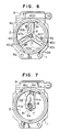
- three radial auxiliary air flow passage portions are formed in different radial directions.
- a spider 3A has a shape which divides the main air flow passage 2 into three portions.
- the spider 3A has in it an axial auxiliary air flow passage portion 40 whose inlet opening is located at the central portion of the main air flow passage 2, and three radial auxiliary air flow passage portions 40a, 40b and 40c having the same form as that of the radial auxiliary air flow passage portions 4e and 4f in the first embodiment. That is, the radial auxiliary air flow passage portions 40a, 40b and 40c respectively have curved portions 40g, 40h and 40i for changing the directions of air flows by about 180°, and outlet openings 40d, 40e and 40f thereof located at the central portion of the main air flow passage 2.
- the radial auxiliary air flow passage portions may be provided in the number of four or more.
- Figs. 7 to 9 are views similar to Fig. 1 and show the states of the air flow meters in which the passage covers are removed.
- a cantilever type spider 3B has an axial auxiliary air flow passage portion 41 whose inlet opening is located at the central portion of the main air flow passage 2, and one radial auxiliary air flow passage portion 41a having the same form as that of the radial auxiliary air flow passage portions 4e and 4f in the first embodiment. That is, the radial auxiliary air flow passage portion 41a has a curved portion 41c for changing the direction of air flow by about 180°, and an outlet opening 41b thereof is located at the central portion of the main air flow passage 2.
- a sensor unit consisting of the spider 3B formed separately from the body 1 and an integral electronic control module mounted on the spider 3B, may be detachably mounted on the body 1.
- the structure of the body 1 which defines the main air flow passage is simplified.
- the sensor unit can be handled as a single unit, initial adjustment and maintenance of the electronic control module are facilitated.
- a spider 3C is disposed across the main air flow passage 2, like the spider 3 shown in Fig. 1.
- the spider 3C has in it an axial auxiliary air flow passage portion 42 whose inlet opening is located at the central portion of the main air flow passage 2, and a radial auxiliary air flow passage portion 42a having a single outlet opening 42b at the central portion of the main air flow passage 2 and two curved portions 42c and 42d for respectively changing the direction of air flow by about 180°. Consequently, the length of the auxiliary air flow passage is increased to about four times that of the radius of the main air flow passage.
- a spider 3D is of the cantilever type, as in the case of the third embodiment shown in Fig. 7.
- the spider 3D has in it an axial auxiliary air flow passage portion 43 whose inlet opening is located at the central portion of the main air flow passage 2, and a composite radial auxiliary air flow passage portion 43e consisting of a single radial air flow passage portion 43a connected to the axial auxiliary air flow passage portion 43 and two divided air flow passage portions 43b and 43c branching from the radial air flow passage portion 43a.
- the air flow passage portions 43b and 43c of the radial auxiliary air flow passage portion 43e respectively have outlet openings 43f and 43g at the central portion of the main air flow passage.
- the portions of the divided air flow passage portions 43b and 43c which are blanched from the single air flow passage portion 43a are curved to form curved portions 43h and 43i for changing the direction of air flow by about 180°.
- a sensor unit that can be detachably mounted on the body 1 by the spider 3D and the electronic control module 9, as in the case of the embodiment shown in Fig. 7. Such a structure facilitates initial adjustment and maintenance of the electronic control module.
- a spider 3E is disposed across the main air flow passage 2, like the spider 3 shown in Fig. 1.
- the spider 3E has in it an axial auxiliary air flow passage portion 44 whose inlet is located at the central portion of the main air flow passage 2, and a single radial auxiliary air flow passage portion 44a having a curved portion 44c for changing the direction of air flow by about 180°.
- An outlet opening 44b of the radial auxiliary air flow passage portion 44a is located at a position offset from the axis of the main air flow passage 2.
- a spider 3F is disposed across the main air flow passage 2.
- the spider 3F has in it an axial auxiliary air flow passage portion 45 whose inlet is located at a position offset from the axis of the main air flow passage 2, and a single radial auxiliary air flow passage portion 45a having a curved portion 45c for changing the direction of air flow by 180°.
- An outlet opening 45b of the radial auxiliary air flow passage portion 45a is also located at a position offset from the axis of the main air flow passage.
- a spider 3G is disposed across the main air flow passage 2, like the spider 3 shown in Fig. 1.
- the spider 3G has in it an axial auxiliary air flow passage portion 46 whose inlet opening is located at a position offset from the axis of the main air flow passage 2, and a single radial auxiliary air flow passage portion 46a having a curved portion 46c for changing the direction of air flow by about 180°.
- An outlet opening 46b of the radial auxiliary air flow passage 46a is located at the central portion of the main air flow passage 2. Consequently, the length of the auxiliary air flow passage can be increased to about three times that of the radius of the main air flow passage.
- a spider 3I is disposed across the main air flow passage, like the spider 3G shown in Fig. 12.
- the spider has in it an axial auxiliary air flow passage portion 47 whose inlet opening is located at a position offset from the axis of the main air flow passage 2, and a single composite radial auxiliary air flow passage portion 47e consisting of a single radial air flow passage portion 47a connected to the axial auxiliary air flow passage portion 47, and two air flow passage portions 47b and 47c branching from the air flow passage portion 47a, as in the case of the embodiment shown in Fig. 9.
- the air flow passage portions 47b and 47c respectively have outlet openings 47f and 47g at the central portion of the main air flow passage.
- the portions of the air flow passage portions 47b and 47c which branch from the air flow passage portion 47a are curved to form curved portions 47h and 47i for changing the direction of air flow by about 180°.
- the inlet opening of each of the axial auxiliary air flow passage portions 45, 46 and 47 is offset from the center of the main air flow passage.
- the inlet opening may have an elliptical form in order to enhance stability thereof against the unbalanced air flow.
- a hot-wire type air flow meter which is less affected by changes in the unbalanced air flow distribution which occurs upstream of the spider and which can be applied to the air intake systems designed in various manners. It is also possible to provide a hot-wire type air flow meter which decreases the occurrence of the two-value phenomena caused by pulsations in the engine intake air flow and which is hence highly reliable.
Landscapes
- Physics & Mathematics (AREA)
- Fluid Mechanics (AREA)
- General Physics & Mathematics (AREA)
- Measuring Volume Flow (AREA)
Applications Claiming Priority (2)
| Application Number | Priority Date | Filing Date | Title |
|---|---|---|---|
| JP88049/90 | 1990-04-02 | ||
| JP8804990 | 1990-04-02 |
Publications (2)
| Publication Number | Publication Date |
|---|---|
| EP0450563A1 true EP0450563A1 (fr) | 1991-10-09 |
| EP0450563B1 EP0450563B1 (fr) | 1996-07-03 |
Family
ID=13931976
Family Applications (1)
| Application Number | Title | Priority Date | Filing Date |
|---|---|---|---|
| EP91105175A Expired - Lifetime EP0450563B1 (fr) | 1990-04-02 | 1991-04-02 | Débitmètre d'air thermique |
Country Status (4)
| Country | Link |
|---|---|
| US (1) | US5243859A (fr) |
| EP (1) | EP0450563B1 (fr) |
| KR (1) | KR100217793B1 (fr) |
| DE (1) | DE69120576T2 (fr) |
Cited By (4)
| Publication number | Priority date | Publication date | Assignee | Title |
|---|---|---|---|---|
| EP0629862A1 (fr) * | 1993-06-18 | 1994-12-21 | Siemens Aktiengesellschaft | Dispositif de mesure d'un écoulement radial d'un gaz ou d'un liquide avec un pont de wheatstone comprenant quatre résistances dépendant de la température |
| WO1996016317A1 (fr) * | 1994-11-24 | 1996-05-30 | Robert Bosch Gmbh | Dispositif permettant de mesurer le debit volumetrique d'une substance en ecoulement |
| EP0708315A3 (fr) * | 1994-10-18 | 1996-06-26 | Hitachi Ltd | Instrument du type thermique pour la mesure de l'écoulement d'air |
| FR2773610A1 (fr) * | 1998-01-09 | 1999-07-16 | Bosch Gmbh Robert | Dispositif de mesure de la masse d'un milieu circulant dans une conduite |
Families Citing this family (3)
| Publication number | Priority date | Publication date | Assignee | Title |
|---|---|---|---|---|
| JPH08283570A (ja) * | 1995-04-17 | 1996-10-29 | Sumitomo Chem Co Ltd | 樹脂組成物 |
| JP2002005713A (ja) | 2000-04-17 | 2002-01-09 | Denso Corp | 空気流量測定装置 |
| JP2008088937A (ja) * | 2006-10-04 | 2008-04-17 | Mitsubishi Electric Corp | 検出装置及びエンジン制御装置 |
Citations (2)
| Publication number | Priority date | Publication date | Assignee | Title |
|---|---|---|---|---|
| EP0087621A1 (fr) * | 1982-02-08 | 1983-09-07 | Hitachi, Ltd. | Débitmètre d'air pour un moteur à combustion |
| US4709581A (en) * | 1984-09-07 | 1987-12-01 | Hitachi, Ltd. | Air flow meter |
Family Cites Families (1)
| Publication number | Priority date | Publication date | Assignee | Title |
|---|---|---|---|---|
| KR950009044B1 (ko) * | 1987-06-17 | 1995-08-14 | 가부시키가이샤 히타치세이사쿠쇼 | 발열저항식 공기유량측정장치 |
-
1991
- 1991-04-01 KR KR1019910005234A patent/KR100217793B1/ko not_active Expired - Fee Related
- 1991-04-02 DE DE69120576T patent/DE69120576T2/de not_active Expired - Fee Related
- 1991-04-02 EP EP91105175A patent/EP0450563B1/fr not_active Expired - Lifetime
- 1991-04-02 US US07/679,316 patent/US5243859A/en not_active Expired - Lifetime
Patent Citations (2)
| Publication number | Priority date | Publication date | Assignee | Title |
|---|---|---|---|---|
| EP0087621A1 (fr) * | 1982-02-08 | 1983-09-07 | Hitachi, Ltd. | Débitmètre d'air pour un moteur à combustion |
| US4709581A (en) * | 1984-09-07 | 1987-12-01 | Hitachi, Ltd. | Air flow meter |
Non-Patent Citations (2)
| Title |
|---|
| PATENT ABSTRACTS OF JAPAN, unexamined applications, P field, vol. 13, No. 508, 15 November 1989; THE PATENT OFFICE JAPANESE GOVERNMENT, page 106, P 960. * |
| PATENT ABSTRACTS OF JAPAN, unexamined applications, P field, vol. 6, No. 141, 30 July 1982; THE PATENT OFFICE JAPANESE GOVERNMENT, page 120, P 131. * |
Cited By (7)
| Publication number | Priority date | Publication date | Assignee | Title |
|---|---|---|---|---|
| EP0629862A1 (fr) * | 1993-06-18 | 1994-12-21 | Siemens Aktiengesellschaft | Dispositif de mesure d'un écoulement radial d'un gaz ou d'un liquide avec un pont de wheatstone comprenant quatre résistances dépendant de la température |
| EP0708315A3 (fr) * | 1994-10-18 | 1996-06-26 | Hitachi Ltd | Instrument du type thermique pour la mesure de l'écoulement d'air |
| US5696321A (en) * | 1994-10-18 | 1997-12-09 | Hitachi, Ltd. | Thermal-type air flow measuring instrument with fluid-direction judging capability |
| EP1146320A1 (fr) * | 1994-10-18 | 2001-10-17 | Hitachi, Ltd. | Dispositif de mesure thermique de débit d'air |
| EP1304551A1 (fr) * | 1994-10-18 | 2003-04-23 | Hitachi, Ltd. | Débitmètre à air du type thermique |
| WO1996016317A1 (fr) * | 1994-11-24 | 1996-05-30 | Robert Bosch Gmbh | Dispositif permettant de mesurer le debit volumetrique d'une substance en ecoulement |
| FR2773610A1 (fr) * | 1998-01-09 | 1999-07-16 | Bosch Gmbh Robert | Dispositif de mesure de la masse d'un milieu circulant dans une conduite |
Also Published As
| Publication number | Publication date |
|---|---|
| US5243859A (en) | 1993-09-14 |
| KR910018780A (ko) | 1991-11-30 |
| DE69120576T2 (de) | 1996-11-07 |
| EP0450563B1 (fr) | 1996-07-03 |
| KR100217793B1 (ko) | 1999-09-01 |
| DE69120576D1 (de) | 1996-08-08 |
Similar Documents
| Publication | Publication Date | Title |
|---|---|---|
| EP0660090B1 (fr) | Arrangement d'un débitmètre d'air de type à fil chaud pour moteurs à combustion interne | |
| EP0933620B1 (fr) | Boitier pour débitmètre et procédé | |
| US5672822A (en) | Thermal flow meter with less turbulence in fluid flow | |
| US6003490A (en) | Throttle device having air flow compensation function | |
| JP3478592B2 (ja) | 空気流量センサー構造 | |
| EP0386966A2 (fr) | Débimètre d'air à fil chaud et moteur à combustion interne pourvu du même | |
| JPH06194199A (ja) | 空気流量測定装置 | |
| US5581026A (en) | Flow meter | |
| KR940000704Y1 (ko) | 와동 유량계 | |
| EP0450563A1 (fr) | Débitmètre d'air thermique | |
| US6101869A (en) | Air flow rate measuring device for an internal combustion engine | |
| US4232549A (en) | Two stage flowmeter | |
| EP0487346A2 (fr) | Débimètre d'air | |
| US4136565A (en) | Variable geometry fluid flowmeter | |
| EP0218216B1 (fr) | Débitmètre d'air d'admission | |
| JP4108842B2 (ja) | エアクリーナ | |
| US5119672A (en) | Air flow rate meter | |
| US5201216A (en) | Air flow meter for internal combustion engines and a manufacturing method thereof | |
| JP2921150B2 (ja) | 熱式空気流量計 | |
| CA1158896A (fr) | Debitmetre reglable a circulation unique | |
| US5908991A (en) | Karman vortex flow meter | |
| EP0107641A2 (fr) | Débitmètre à vortex | |
| KR100255475B1 (ko) | 유량계 | |
| US5193399A (en) | Vortex flowmeter | |
| JPH11229979A (ja) | エアクリーナ |
Legal Events
| Date | Code | Title | Description |
|---|---|---|---|
| PUAI | Public reference made under article 153(3) epc to a published international application that has entered the european phase |
Free format text: ORIGINAL CODE: 0009012 |
|
| AK | Designated contracting states |
Kind code of ref document: A1 Designated state(s): DE GB |
|
| 17P | Request for examination filed |
Effective date: 19911014 |
|
| 17Q | First examination report despatched |
Effective date: 19940120 |
|
| GRAH | Despatch of communication of intention to grant a patent |
Free format text: ORIGINAL CODE: EPIDOS IGRA |
|
| GRAA | (expected) grant |
Free format text: ORIGINAL CODE: 0009210 |
|
| AK | Designated contracting states |
Kind code of ref document: B1 Designated state(s): DE GB |
|
| REF | Corresponds to: |
Ref document number: 69120576 Country of ref document: DE Date of ref document: 19960808 |
|
| PLBE | No opposition filed within time limit |
Free format text: ORIGINAL CODE: 0009261 |
|
| STAA | Information on the status of an ep patent application or granted ep patent |
Free format text: STATUS: NO OPPOSITION FILED WITHIN TIME LIMIT |
|
| 26N | No opposition filed | ||
| REG | Reference to a national code |
Ref country code: GB Ref legal event code: IF02 |
|
| PGFP | Annual fee paid to national office [announced via postgrant information from national office to epo] |
Ref country code: GB Payment date: 20080329 Year of fee payment: 18 |
|
| PGFP | Annual fee paid to national office [announced via postgrant information from national office to epo] |
Ref country code: DE Payment date: 20080606 Year of fee payment: 18 |
|
| GBPC | Gb: european patent ceased through non-payment of renewal fee |
Effective date: 20090402 |
|
| PG25 | Lapsed in a contracting state [announced via postgrant information from national office to epo] |
Ref country code: DE Free format text: LAPSE BECAUSE OF NON-PAYMENT OF DUE FEES Effective date: 20091103 |
|
| PG25 | Lapsed in a contracting state [announced via postgrant information from national office to epo] |
Ref country code: GB Free format text: LAPSE BECAUSE OF NON-PAYMENT OF DUE FEES Effective date: 20090402 |