EP0450909A1 - Connecteur réversible - Google Patents
Connecteur réversible Download PDFInfo
- Publication number
- EP0450909A1 EP0450909A1 EP91302868A EP91302868A EP0450909A1 EP 0450909 A1 EP0450909 A1 EP 0450909A1 EP 91302868 A EP91302868 A EP 91302868A EP 91302868 A EP91302868 A EP 91302868A EP 0450909 A1 EP0450909 A1 EP 0450909A1
- Authority
- EP
- European Patent Office
- Prior art keywords
- coupling
- locking
- contact
- contacts
- coupling member
- Prior art date
- Legal status (The legal status is an assumption and is not a legal conclusion. Google has not performed a legal analysis and makes no representation as to the accuracy of the status listed.)
- Granted
Links
Images
Classifications
-
- H—ELECTRICITY
- H01—ELECTRIC ELEMENTS
- H01R—ELECTRICALLY-CONDUCTIVE CONNECTIONS; STRUCTURAL ASSOCIATIONS OF A PLURALITY OF MUTUALLY-INSULATED ELECTRICAL CONNECTING ELEMENTS; COUPLING DEVICES; CURRENT COLLECTORS
- H01R24/00—Two-part coupling devices, or either of their cooperating parts, characterised by their overall structure
- H01R24/84—Hermaphroditic coupling devices
-
- H—ELECTRICITY
- H01—ELECTRIC ELEMENTS
- H01R—ELECTRICALLY-CONDUCTIVE CONNECTIONS; STRUCTURAL ASSOCIATIONS OF A PLURALITY OF MUTUALLY-INSULATED ELECTRICAL CONNECTING ELEMENTS; COUPLING DEVICES; CURRENT COLLECTORS
- H01R24/00—Two-part coupling devices, or either of their cooperating parts, characterised by their overall structure
- H01R24/38—Two-part coupling devices, or either of their cooperating parts, characterised by their overall structure having concentrically or coaxially arranged contacts
- H01R24/40—Two-part coupling devices, or either of their cooperating parts, characterised by their overall structure having concentrically or coaxially arranged contacts specially adapted for high frequency
- H01R24/56—Two-part coupling devices, or either of their cooperating parts, characterised by their overall structure having concentrically or coaxially arranged contacts specially adapted for high frequency specially adapted to a specific shape of cables, e.g. corrugated cables, twisted pair cables, cables with two screens or hollow cables
Definitions
- This invention relates to the field of cable coupling, and in particular to a hermaphroditic coupling mechanism for a cable contact arrangement.
- pin and socket contact permits connection of two cables by simply sliding a pin on one cable into a socket on the other.
- pin and socket contact One type of widely used pin and socket contact, is the "twinax" contact which is used to connect cables carrying two electrical wires surrounded by a common jacket.
- latching mechanism Because it is desirable to design such contacts to be as simple as possible, many of the conventional pin and socket contact arrangements lack any sort of latching mechanism. This is completely satisfactory for uses in which no strain is placed on the cables in a direction which would cause the contacts to be pulled apart. However, for many applications, some type of latching mechanism is required in order to prevent the contacts from pulling apart. The most common means of providing this latching mechanism is by trapping the contact inside an elaborate connector. The connector then provides the mating and unmating mechanism as well as the latching mechanism.
- hermaphroditic or sexless coupling mechanisms are known. Nevertheless, hermaphroditic coupling mechanisms which may be easily retrofitted onto conventional contacts have so far not been developed, thus limiting application of the known hermaphroditic couplers.
- a coupling mechanism which includes two identical coupling members, each of which includes a latching arm provided with a latch arm ramp surface which faces an interface portion of the coupler member, and a complimentary locking ramp surface which faces away from the interface portion of the coupler.
- the locking ramp surface includes a detent over which the latch arm ramp surface passes when the coupler members are rotated relative to each other, the detent thereafter holding the latch arm ramp surface relative to the locking ramp surface in order to secure the couplers together.
- the locking ramp surface is provided on a collar which extends around the coupler member and which includes a groove through which the latching arm is inserted prior to relative rotation of the couplers.
- the coupling members are easily retrofitted onto respective contacts by a ramp and detent mechanism provided in an inner bore of the coupler.
- the contact is inserted into the bore until a collar on the contact passes over the detent and is retained thereby.
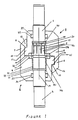
- Figure 1 is a cross-sectional view of a mated coupler and twinax contact pair according to a preferred embodiment of the invention.
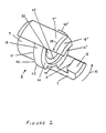
- Figure 2 is an isometric view of one of the couplers of the pair shown in Figure 1.
- Figures 1 and 2 illustrate a coupling mechanism for coupling two cable contacts and locking them against disengagement according to a preferred embodiment of the invention.
- the contacts illustrated are "twinax" contacts, one of which is a pin and the other a socket, it will be appreciated that any of a large variety of cable contacts, including power coaxial and triaxial contacts, may be used with the coupler mechanism of the invention.
- twinax contact pin 1 slides into twinax contact socket 2 to effect an electrical connection between two twin axial cables (not shown).
- the manner in which the contacts are connected to the cables is conventional and forms no part of the invention.
- the pin 1 and socket 2 would be free to disengage from each other because they do not include an internal latching mechanism, other than the resilience of the tines 3 which form part of socket 2.
- the coupler mechanism of the invention is intended to prevent such disengagement, and may be used with any contact mechanism which might otherwise be disengageable under tension.
- FIG 2 is a perspective view of coupling member 5, which is identical in structure to coupling member 4.
- Coupling member 5 is generally cylindrical in shape, the axis of the cylinder coinciding with principal axis 14 of the two contacts 1 and 2 as shown in Figure 1.
- the coupling member shown in Figure 2 includes two latch arms extending from a main body 9 of the coupling member, and two locking ramp surfaces provided on a collar 18 which extends generally around main body 9. Because the coupling member has a 180 degree mirror symmetry, i.e., the coupler member will always appear identical when rotated 180 degrees, only one of the latch arms and one of the locking arms ramps is described in detail. Elements having primed reference numerals (e.g., latch arm 7′ and groove 24′) are identical to corresponding unprimed elements (e.g., latch arm 7 and groove 24).
- Latch arm 7 includes a latch arm ramp surface 11 which is engageable with a complementary ramp surface 21 on the corresponding mating coupling member 4 and which faces an interface portion 20 of coupler member 5.
- Interface 20 is an annular surface surrounding the bore 26 through which the contacts are inserted.
- Ramp surface 11 is provided on a radially inward extending projection 13 at the distal end of latch arm 7.
- a corresponding latch arm 6 including projection 12 and ramp surface 10 is provided on coupler member 4 and is engageable with ramp surface 21 on coupler member 5.
- Interface surface 20 faces a corresponding interface surface 19 when the two coupling members 4 and 5 are joined as shown in Figure 1. Although illustrated as being slightly apart after coupling, it is also contemplated that the coupling members may contact each other, or contact each other during coupling and then separate.
- Locking ramp surface 21 faces away from interface surface 20 and is provided on collar 18, best shown in Figure 2.
- a detent 22 on each of the ramp surfaces provides the means by which coupled coupler member 4 and 5 are coupled, as will be described in more detail below.
- Collar 18 includes a latch bypass groove 24 which permits corresponding projection 12 of latch arm 6 on coupler member 4 to be inserted through the collar.
- Groove 24 must be wide enough to permit passage of the corresponding latch arm 6 and ramp 10 on the mating coupling member 4, and must be positioned such that complementary locking latches will not interfere with each other when the coupling members 4 and 5 are united.
- collar 18 extends around main body 9 and therefore includes a second, mirror symmetric, groove 24′, and that coupler member 4 is provided with identical grooves provided in collar 17.
- bypass groove 24 be located adjacent a locking latch arm as shown. However, this is not essential as long as it is possible for the corresponding latch arm 6 on coupler 4 to bypass collar 18 and engage locking ramp surface 21 provided on the collar.
- Ramp surface 21 generally slopes away from the mating interface in the direction in which the corresponding coupling member 4 will be turned during the latching process.
- the locking direction for member 5 shall be counter-clockwise as indicated by arrows 35, although a clockwise locking direction could easily be obtained by locating bypass groove 24 adjacent the other of the locking latches 7′and by sloping the ramp surface 11 in a direction opposite the direction shown.
- detent 22 is designed so that latch arm ramp surface 10 on latch arm 6 of member 4 will pass over the detent and engage ramp surface 21 upon coupling, detent 22 preventing backwards rotational movement of member 4 upon engagement. The operation of the coupling mechanism will be described more fully below.
- interface surfaces 19 and 20 between the coupling members 4 and 5 preferably each includes a groove for retaining o-rings 38 and 27 which effect an environmental seal between the coupled unit formed by members 4 and 5. It will of course be appreciated that other environmental sealing arrangements will also occur to those skilled in the art.
- o-rings 38 and 27 may provide resilience in order to bias the latch arm ramp surfaces against respective locking ramp surfaces.
- the latch arms or the detents may be formed of a plastically deformable material such that the material deforms as the latching ramp surfaces ride over the detents during coupling, the restoring force of the material causing the detents to regain their shape in order to retain the latch arms in place.
- coupling members 4 and 5 preferably also include a contact snap retention feature.
- a ramp and a detent are located on the inner surface of bores 26 and 46 in each of members 4 and 5 through which the contacts are separately inserted.
- Contacts 1 and 2 are provided in this embodiment with annular collars 28 and 31. During separate insertion of the contacts into bore 26 and 46, the collars press against respective ramp surfaces 29 and 32, which plastically deform until the collars pass detents 30 and 33, at which time the ramps and detents are restored to their original positions, holding the collars in place against annular shoulders 40 and 41.
- the contacts may be retained within the coupling members by any of a variety of suitable contact retention mechanisms, and also that retention may be obtained without any additional means provided on the members, for example by an interference fit.
- grooves 36 and 39 are provided in the main bodies 8 and 9 of each coupling member for holding seals 34 and 37, preferably o-rings, between the respective contacts and bodies to seal the rear of each coupling member.
- Coupling numbers 4 and 5 are first respectively secured on pin 1 and socket 2 by inserting the respective contacts through bores 26 and 46 until collars 28 and 31 pass detents 30 and 33, which plastically deform as the collars pass the detents, after which the time the ramps and detents are restored to their original position, holding the collars in place against annular shoulders 40 and 41.
- the respective coupling members must be inserted over the cables or secured to their contacts before the cables are connected thereto.
- the order of the ramps, detents and annular shoulders those skilled in the art will recognize that it would then be possible to slide the coupling member over contact from the leading portion of the contact rather than from the cable side of the contact, thus permitting the coupling member to be added after the contact had already been secured to the cable.
- the coupling members Once the coupling members have been snap-locked onto the respective contacts, they are coupled by initially aligning respective latch arms with respective grooves on the complimentary locking members. The pin and socket are slid together as the aligned latch arms are inserted through the grooves. The coupling members 4 and 5 are then rotated in a counter-clockwise direction relative to each other in the preferred embodiment, so that the latch arm ramp surfaces ride up over the groove curved surfaces, over the detents, and onto the locking ramp surfaces, at which point the coupling members are locked together preventing disengagement of the contacts.
- each coupling member while desirable, is not essential.
- the invention would work with a single latch arm or with, for example, three latch arms and locking ramps having a 120 degree symmetry.
Landscapes
- Details Of Connecting Devices For Male And Female Coupling (AREA)
- Dental Preparations (AREA)
- Measurement And Recording Of Electrical Phenomena And Electrical Characteristics Of The Living Body (AREA)
- Snaps, Bayonet Connections, Set Pins, And Snap Rings (AREA)
- Connection Of Plates (AREA)
- Pens And Brushes (AREA)
- Inks, Pencil-Leads, Or Crayons (AREA)
- Polyesters Or Polycarbonates (AREA)
- Developing Agents For Electrophotography (AREA)
- Nitrogen And Oxygen Or Sulfur-Condensed Heterocyclic Ring Systems (AREA)
- Saccharide Compounds (AREA)
- Pharmaceuticals Containing Other Organic And Inorganic Compounds (AREA)
Applications Claiming Priority (2)
| Application Number | Priority Date | Filing Date | Title |
|---|---|---|---|
| US50269390A | 1990-04-02 | 1990-04-02 | |
| US502693 | 1990-04-02 |
Publications (2)
| Publication Number | Publication Date |
|---|---|
| EP0450909A1 true EP0450909A1 (fr) | 1991-10-09 |
| EP0450909B1 EP0450909B1 (fr) | 1995-11-29 |
Family
ID=23998965
Family Applications (1)
| Application Number | Title | Priority Date | Filing Date |
|---|---|---|---|
| EP91302868A Expired - Lifetime EP0450909B1 (fr) | 1990-04-02 | 1991-04-02 | Connecteur réversible |
Country Status (6)
| Country | Link |
|---|---|
| EP (1) | EP0450909B1 (fr) |
| AT (1) | ATE130969T1 (fr) |
| DE (1) | DE69114888T2 (fr) |
| DK (1) | DK0450909T3 (fr) |
| ES (1) | ES2080892T3 (fr) |
| GR (1) | GR3018656T3 (fr) |
Cited By (6)
| Publication number | Priority date | Publication date | Assignee | Title |
|---|---|---|---|---|
| WO1994016474A1 (fr) * | 1992-12-31 | 1994-07-21 | Connector Systems Technology N.V. | Systeme d'interconnexion |
| EP0875959A1 (fr) * | 1997-04-30 | 1998-11-04 | Interlemo Holding S.A. | Système de connexion |
| GB2326538A (en) * | 1997-06-20 | 1998-12-23 | Nokia Mobile Phones Ltd | Bayonet connector |
| FR2765034A1 (fr) * | 1997-06-19 | 1998-12-24 | Framatome Connectors France | Mecanisme de verrouillage hermaphrodite |
| FR2782197A1 (fr) * | 1998-08-06 | 2000-02-11 | Sercel Rech Const Elect | Dispositif hermaphrodite de connexion electrique |
| US6227895B1 (en) | 1997-04-30 | 2001-05-08 | Intertemo Holding S.A. | Connector system |
Families Citing this family (2)
| Publication number | Priority date | Publication date | Assignee | Title |
|---|---|---|---|---|
| DE102017118251A1 (de) * | 2017-08-10 | 2019-02-14 | Airbus Operations Gmbh | Kopplungselement und Kopplungssystem sowie Verfahren zum Koppeln von zwei Modulen und Luftfahrzeug |
| DE102024103972A1 (de) * | 2024-02-13 | 2025-08-14 | Harting Electric Stiftung & Co. Kg | Hermaphroditisches Isoliergehäuse für einen Steckverbinder, Steckverbindersystem, Baugruppe, Verfahren und Bausatz |
Citations (4)
| Publication number | Priority date | Publication date | Assignee | Title |
|---|---|---|---|---|
| US3252124A (en) * | 1961-03-10 | 1966-05-17 | Wago Klemmenwerk G M B H | Push-in connector |
| DE2115580A1 (de) * | 1970-03-31 | 1971-11-11 | Staff & Schwarz Gmbh | Elektrische Kupplung zum Verbinden elektrischer Leitungen oder Kontakte |
| EP0132099A2 (fr) * | 1983-07-15 | 1985-01-23 | Sumitomo Wiring Systems, Ltd. | Connecteur étanche à l'eau |
| DE8804091U1 (de) * | 1988-03-25 | 1988-05-26 | Grote & Hartmann Gmbh & Co Kg, 5600 Wuppertal | Elektrischer Steckverbinder |
-
1991
- 1991-04-02 AT AT91302868T patent/ATE130969T1/de not_active IP Right Cessation
- 1991-04-02 ES ES91302868T patent/ES2080892T3/es not_active Expired - Lifetime
- 1991-04-02 EP EP91302868A patent/EP0450909B1/fr not_active Expired - Lifetime
- 1991-04-02 DK DK91302868.4T patent/DK0450909T3/da active
- 1991-04-02 DE DE69114888T patent/DE69114888T2/de not_active Expired - Fee Related
-
1996
- 1996-01-11 GR GR960400054T patent/GR3018656T3/el unknown
Patent Citations (4)
| Publication number | Priority date | Publication date | Assignee | Title |
|---|---|---|---|---|
| US3252124A (en) * | 1961-03-10 | 1966-05-17 | Wago Klemmenwerk G M B H | Push-in connector |
| DE2115580A1 (de) * | 1970-03-31 | 1971-11-11 | Staff & Schwarz Gmbh | Elektrische Kupplung zum Verbinden elektrischer Leitungen oder Kontakte |
| EP0132099A2 (fr) * | 1983-07-15 | 1985-01-23 | Sumitomo Wiring Systems, Ltd. | Connecteur étanche à l'eau |
| DE8804091U1 (de) * | 1988-03-25 | 1988-05-26 | Grote & Hartmann Gmbh & Co Kg, 5600 Wuppertal | Elektrischer Steckverbinder |
Cited By (10)
| Publication number | Priority date | Publication date | Assignee | Title |
|---|---|---|---|---|
| WO1994016474A1 (fr) * | 1992-12-31 | 1994-07-21 | Connector Systems Technology N.V. | Systeme d'interconnexion |
| EP0875959A1 (fr) * | 1997-04-30 | 1998-11-04 | Interlemo Holding S.A. | Système de connexion |
| WO1998049753A1 (fr) * | 1997-04-30 | 1998-11-05 | Interlemo Holding S.A. | Systeme de connexion |
| AU726404B2 (en) * | 1997-04-30 | 2000-11-09 | Interlemo Holding S.A. | Connector system |
| US6227895B1 (en) | 1997-04-30 | 2001-05-08 | Intertemo Holding S.A. | Connector system |
| FR2765034A1 (fr) * | 1997-06-19 | 1998-12-24 | Framatome Connectors France | Mecanisme de verrouillage hermaphrodite |
| EP0887895A1 (fr) * | 1997-06-19 | 1998-12-30 | Framatome Connectors International | Mécanisme de verrouillage hermaphrodite |
| GB2326538A (en) * | 1997-06-20 | 1998-12-23 | Nokia Mobile Phones Ltd | Bayonet connector |
| FR2782197A1 (fr) * | 1998-08-06 | 2000-02-11 | Sercel Rech Const Elect | Dispositif hermaphrodite de connexion electrique |
| WO2000008724A1 (fr) * | 1998-08-06 | 2000-02-17 | Sercel | Dispositif hermaphrodite de connexion electrique |
Also Published As
| Publication number | Publication date |
|---|---|
| DE69114888D1 (de) | 1996-01-11 |
| ATE130969T1 (de) | 1995-12-15 |
| EP0450909B1 (fr) | 1995-11-29 |
| GR3018656T3 (en) | 1996-04-30 |
| ES2080892T3 (es) | 1996-02-16 |
| DK0450909T3 (da) | 1996-02-26 |
| DE69114888T2 (de) | 1996-04-18 |
Similar Documents
| Publication | Publication Date | Title |
|---|---|---|
| US5118303A (en) | Hermaphroditic coupler | |
| US3885851A (en) | Push-pull connector | |
| US6206579B1 (en) | Arrangement for integrating a rectangular fiber optic connector into a cylindrical connector | |
| US7074066B2 (en) | Sealed electrical connector having internal latching mechanism therefore | |
| EP0898723B1 (fr) | Connecteur électrique-optique à accouplement immergé | |
| JP4213891B2 (ja) | 湿式嵌合コネクタ | |
| US4637674A (en) | Annular connector seal | |
| US5984709A (en) | Electric connector | |
| US5823813A (en) | Connector position assurance device | |
| US3810073A (en) | Connector locking mechanism | |
| US20040106320A1 (en) | Coupling mechanism for electrical connectors | |
| US20020090856A1 (en) | Coax cable connector assembly with latching housing | |
| EP1225660A2 (fr) | Connecteur électrique coaxial encliquetable à angle droit | |
| US10355406B2 (en) | Electrical connector | |
| CA2352541A1 (fr) | Boitier pour fiches electriques | |
| US5820400A (en) | Half-fitting preventing connector | |
| EP0121610A1 (fr) | Système de couplage notamment pour un connecteur | |
| EP0450909B1 (fr) | Connecteur réversible | |
| US4500154A (en) | Electrical connector assembly having an anti-decoupling device | |
| EP1039590A3 (fr) | Assemblage de connecteur électrique | |
| EP1130691A3 (fr) | Connecteur à levier | |
| US20220320801A1 (en) | Retainer Resisting Decoupling Of Electrical Cords | |
| US4907981A (en) | Quick-release electrical connector coupling device | |
| WO2001042839A3 (fr) | Systemes de connecteurs hermaphrodites | |
| EP0971456B1 (fr) | Verrouillage positif de connecteur |
Legal Events
| Date | Code | Title | Description |
|---|---|---|---|
| PUAI | Public reference made under article 153(3) epc to a published international application that has entered the european phase |
Free format text: ORIGINAL CODE: 0009012 |
|
| AK | Designated contracting states |
Kind code of ref document: A1 Designated state(s): AT BE CH DE DK ES FR GB GR IT LI LU NL SE |
|
| 17P | Request for examination filed |
Effective date: 19920312 |
|
| 17Q | First examination report despatched |
Effective date: 19940603 |
|
| GRAA | (expected) grant |
Free format text: ORIGINAL CODE: 0009210 |
|
| AK | Designated contracting states |
Kind code of ref document: B1 Designated state(s): AT BE CH DE DK ES FR GB GR IT LI LU NL SE |
|
| REF | Corresponds to: |
Ref document number: 130969 Country of ref document: AT Date of ref document: 19951215 Kind code of ref document: T |
|
| ITF | It: translation for a ep patent filed | ||
| REF | Corresponds to: |
Ref document number: 69114888 Country of ref document: DE Date of ref document: 19960111 |
|
| REG | Reference to a national code |
Ref country code: CH Ref legal event code: NV Representative=s name: KIRKER & CIE SA |
|
| REG | Reference to a national code |
Ref country code: ES Ref legal event code: FG2A Ref document number: 2080892 Country of ref document: ES Kind code of ref document: T3 |
|
| ET | Fr: translation filed | ||
| REG | Reference to a national code |
Ref country code: DK Ref legal event code: T3 |
|
| REG | Reference to a national code |
Ref country code: GR Ref legal event code: FG4A Free format text: 3018656 |
|
| PLBE | No opposition filed within time limit |
Free format text: ORIGINAL CODE: 0009261 |
|
| STAA | Information on the status of an ep patent application or granted ep patent |
Free format text: STATUS: NO OPPOSITION FILED WITHIN TIME LIMIT |
|
| 26N | No opposition filed | ||
| REG | Reference to a national code |
Ref country code: GB Ref legal event code: IF02 |
|
| PGFP | Annual fee paid to national office [announced via postgrant information from national office to epo] |
Ref country code: AT Payment date: 20060314 Year of fee payment: 16 Ref country code: GB Payment date: 20060314 Year of fee payment: 16 |
|
| PGFP | Annual fee paid to national office [announced via postgrant information from national office to epo] |
Ref country code: DK Payment date: 20060317 Year of fee payment: 16 |
|
| PGFP | Annual fee paid to national office [announced via postgrant information from national office to epo] |
Ref country code: NL Payment date: 20060324 Year of fee payment: 16 |
|
| PGFP | Annual fee paid to national office [announced via postgrant information from national office to epo] |
Ref country code: LU Payment date: 20060328 Year of fee payment: 16 |
|
| PGFP | Annual fee paid to national office [announced via postgrant information from national office to epo] |
Ref country code: FR Payment date: 20060403 Year of fee payment: 16 |
|
| PGFP | Annual fee paid to national office [announced via postgrant information from national office to epo] |
Ref country code: SE Payment date: 20060404 Year of fee payment: 16 |
|
| PGFP | Annual fee paid to national office [announced via postgrant information from national office to epo] |
Ref country code: GR Payment date: 20060406 Year of fee payment: 16 |
|
| PGFP | Annual fee paid to national office [announced via postgrant information from national office to epo] |
Ref country code: ES Payment date: 20060424 Year of fee payment: 16 |
|
| PGFP | Annual fee paid to national office [announced via postgrant information from national office to epo] |
Ref country code: BE Payment date: 20060425 Year of fee payment: 16 |
|
| PGFP | Annual fee paid to national office [announced via postgrant information from national office to epo] |
Ref country code: DE Payment date: 20060428 Year of fee payment: 16 |
|
| PGFP | Annual fee paid to national office [announced via postgrant information from national office to epo] |
Ref country code: IT Payment date: 20060430 Year of fee payment: 16 |
|
| PGFP | Annual fee paid to national office [announced via postgrant information from national office to epo] |
Ref country code: CH Payment date: 20060608 Year of fee payment: 16 |
|
| REG | Reference to a national code |
Ref country code: DK Ref legal event code: EBP |
|
| REG | Reference to a national code |
Ref country code: CH Ref legal event code: PL |
|
| GBPC | Gb: european patent ceased through non-payment of renewal fee |
Effective date: 20070402 |
|
| BERE | Be: lapsed |
Owner name: *AMPHENOL CORP. Effective date: 20070430 |
|
| NLV4 | Nl: lapsed or anulled due to non-payment of the annual fee |
Effective date: 20071101 |
|
| PG25 | Lapsed in a contracting state [announced via postgrant information from national office to epo] |
Ref country code: NL Free format text: LAPSE BECAUSE OF NON-PAYMENT OF DUE FEES Effective date: 20071101 Ref country code: DE Free format text: LAPSE BECAUSE OF NON-PAYMENT OF DUE FEES Effective date: 20071101 |
|
| PG25 | Lapsed in a contracting state [announced via postgrant information from national office to epo] |
Ref country code: LI Free format text: LAPSE BECAUSE OF NON-PAYMENT OF DUE FEES Effective date: 20070430 Ref country code: AT Free format text: LAPSE BECAUSE OF NON-PAYMENT OF DUE FEES Effective date: 20070402 Ref country code: CH Free format text: LAPSE BECAUSE OF NON-PAYMENT OF DUE FEES Effective date: 20070430 |
|
| PG25 | Lapsed in a contracting state [announced via postgrant information from national office to epo] |
Ref country code: BE Free format text: LAPSE BECAUSE OF NON-PAYMENT OF DUE FEES Effective date: 20070430 |
|
| PG25 | Lapsed in a contracting state [announced via postgrant information from national office to epo] |
Ref country code: GB Free format text: LAPSE BECAUSE OF NON-PAYMENT OF DUE FEES Effective date: 20070402 Ref country code: DK Free format text: LAPSE BECAUSE OF NON-PAYMENT OF DUE FEES Effective date: 20070430 |
|
| PG25 | Lapsed in a contracting state [announced via postgrant information from national office to epo] |
Ref country code: SE Free format text: LAPSE BECAUSE OF NON-PAYMENT OF DUE FEES Effective date: 20070403 |
|
| REG | Reference to a national code |
Ref country code: ES Ref legal event code: FD2A Effective date: 20070403 |
|
| PG25 | Lapsed in a contracting state [announced via postgrant information from national office to epo] |
Ref country code: FR Free format text: LAPSE BECAUSE OF NON-PAYMENT OF DUE FEES Effective date: 20070430 |
|
| PG25 | Lapsed in a contracting state [announced via postgrant information from national office to epo] |
Ref country code: GR Free format text: LAPSE BECAUSE OF NON-PAYMENT OF DUE FEES Effective date: 20071102 Ref country code: ES Free format text: LAPSE BECAUSE OF NON-PAYMENT OF DUE FEES Effective date: 20070403 |
|
| PG25 | Lapsed in a contracting state [announced via postgrant information from national office to epo] |
Ref country code: LU Free format text: LAPSE BECAUSE OF NON-PAYMENT OF DUE FEES Effective date: 20070402 |
|
| PG25 | Lapsed in a contracting state [announced via postgrant information from national office to epo] |
Ref country code: IT Free format text: LAPSE BECAUSE OF NON-PAYMENT OF DUE FEES Effective date: 20070402 |