EP0450928A2 - Reflexionsfreie Viertelwellenlängen-Saw-Wandler - Google Patents
Reflexionsfreie Viertelwellenlängen-Saw-Wandler Download PDFInfo
- Publication number
- EP0450928A2 EP0450928A2 EP91302902A EP91302902A EP0450928A2 EP 0450928 A2 EP0450928 A2 EP 0450928A2 EP 91302902 A EP91302902 A EP 91302902A EP 91302902 A EP91302902 A EP 91302902A EP 0450928 A2 EP0450928 A2 EP 0450928A2
- Authority
- EP
- European Patent Office
- Prior art keywords
- saw
- substrate
- electrodes
- width
- electrode
- Prior art date
- Legal status (The legal status is an assumption and is not a legal conclusion. Google has not performed a legal analysis and makes no representation as to the accuracy of the status listed.)
- Withdrawn
Links
- 238000010897 surface acoustic wave method Methods 0.000 claims description 98
- 239000000758 substrate Substances 0.000 claims description 32
- 230000001902 propagating effect Effects 0.000 claims description 9
- 230000008878 coupling Effects 0.000 claims description 4
- 238000010168 coupling process Methods 0.000 claims description 4
- 238000005859 coupling reaction Methods 0.000 claims description 4
- 238000000034 method Methods 0.000 claims description 4
- 230000000694 effects Effects 0.000 description 2
- 238000012986 modification Methods 0.000 description 2
- 230000004048 modification Effects 0.000 description 2
- 238000005457 optimization Methods 0.000 description 2
- 230000010363 phase shift Effects 0.000 description 2
- 229910003327 LiNbO3 Inorganic materials 0.000 description 1
- 230000001413 cellular effect Effects 0.000 description 1
- 230000007423 decrease Effects 0.000 description 1
- 230000001419 dependent effect Effects 0.000 description 1
- 238000010586 diagram Methods 0.000 description 1
- 239000007772 electrode material Substances 0.000 description 1
- 239000010453 quartz Substances 0.000 description 1
- VYPSYNLAJGMNEJ-UHFFFAOYSA-N silicon dioxide Inorganic materials O=[Si]=O VYPSYNLAJGMNEJ-UHFFFAOYSA-N 0.000 description 1
- 239000007787 solid Substances 0.000 description 1
Images

Classifications
-
- H—ELECTRICITY
- H03—ELECTRONIC CIRCUITRY
- H03H—IMPEDANCE NETWORKS, e.g. RESONANT CIRCUITS; RESONATORS
- H03H9/00—Networks comprising electromechanical or electro-acoustic elements; Electromechanical resonators
- H03H9/02—Details
- H03H9/02535—Details of surface acoustic wave devices
- H03H9/02818—Means for compensation or elimination of undesirable effects
- H03H9/02842—Means for compensation or elimination of undesirable effects of reflections
Definitions
- This invention relates, in general, to surface acoustic wave (SAW) devices, and more specifically, to SAW transducers.
- SAW surface acoustic wave
- SAW devices are increasingly operating at higher frequencies. These higher frequencies demand increasingly higher line resolution in the transducer and filter electrodes.
- An optimum width for SAW electrodes is one-quarter (1/4) wavelength. This width, however, results in reflections of the generated energy. Specifically, as energy encounters an electrode edge, a reflection results at center frequency. As the energy continues through the electrode and encounters the opposite edge, an additional reflection results. This reflected energy combines with other reflected energy and results in major distortion to the SAW.
- Most of the present SAW device electrodes are designed with one-eighth (1/8) or one-sixth (1/6) wavelength widths since these widths eliminate center frequency reflections. Using the smaller wavelength widths decreases the line resolution of the electrodes. Furthermore, the smaller the wavelength, the smaller the electrode must be. For instance, at one GHz, a one-quarter wavelength electrode is approximately .9 microns, while a one-eighth wavelength is approximately .45 microns. Also, the width of the electrode is inversely proportional to the frequency. The one-quarter wavelength electrode facilitates twice the SAW operating frequency as the one-eighth wavelength electrode geometry for a given line width resolution.
- a SAW transducer eliminates mechanical energy reflections by using one-quarter wavelength electrodes spaced at predetermined intervals.
- dummy electrodes are shifted one-quarter wavelength in the direction of energy propagation to cancel energy reflections in the active electrode regions.
- a pair of dummy electrodes is required for each direction of SAW propagation from each active set of electrodes (the active set comprises one positive and two negative electrodes).
- SAW surface acoustic wave
- the invention provides in a method for eliminating energy reflections caused by a propagating surface acoustic wave (SAW) generated within a SAW transducer as the SAW encounters transducer electrodes, the SAW having a direction of propagation through a SAW device substrate, the method comprising the steps of: coupling to the substrate along the direction of SAW propagation a plurality of dummy electrodes which are not actively generating SAWs, each of the plurality of dummy electrodes having a first width of one-quarter wave length; coupling to the substrate at least one electrode having a second width of one-half wave length; phase shifting within the at least one electrode energy reflections from the plurality of dummy electrodes equal to and opposite in phase with the energy reflections caused by the propagating SAW; and combining the phase shifted energy reflections with the energy reflections caused by the propagating SAW to cancel both the phase shifted energy reflections and the reflections caused by the propagating SAW.
- SAW surface acoustic wave
- the invention provides a surface acoustic wave (SAW) transducer, comprising: a substrate for propogating a SAW of predetermined wavelength; a plurality of unit transducers coupled to the substrate, each of the unit transducers comprising; means coupled to the substrate for generating a SAW comprising a plurality of electrodes each having a first width of one-quarter wave length; a plurality of dummy electrodes coupled to the substrate in the direction of SAW propogation, each having a sidth equal to the first width; and at least one electrode coupled to the substrate in the direction of SAW propogation, having a second width of one-half wave length.
- SAW surface acoustic wave
- the invention provides a surface acoustic wave (SAW) transducer formed on a substrate and having one or more unit transducers comprising: means for generating a SAW comprising at least two electrodes coupled to the substrate; and a plurality of dummy electrodes coupled to the substrate in the direction of the SAW propagation, the arrangement being such as to reduce centre frequency reflections.
- SAW surface acoustic wave
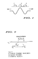
- FIG. 1 is a schematic describing how a surface acoustic wave (SAW) is generated.
- SAW surface acoustic wave
- FIG. 2 diagrams how reflections are caused within SAW transducers.
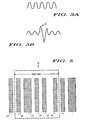
- FIG. 3 shows how reflections within a conventional SAW transducer affect a SAW.
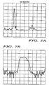
- FIG. 4 shows SAW response curves for a conventional SAW transducer using quarter wavelength electrodes.
- FIG. 5 is a schematic of a unit cell for a SAW transducer according to the present invention.
- FIG. 6 is a schematic of a SAW transducer according to the present invention.
- FIG. 7 show SAW response curves for the transducer of FIG. 6.
- FIG. 1 shows how a surface acoustic wave (SAW) is generated within a piezoelectric substrate, such as quartz.
- SAW surface acoustic wave
- a positive charged electrode 4 is separated from two negatively charged electrodes 6 and 7 a distance equal to the width of one of the electrodes.
- the electrodes and the accompanying substrate generate a SAW which propagates in both longitudinal directions.
- FIG. 2 shows the effect on a SAW encountering an additional active electrode.
- a SAW reflection from the front edge of a quarter wavelength electrode A R 1 is assumed to be 0° and is in the opposite direction from the incident SAW (labelled A I ).
- a I the incident SAW
- FIG. 3 shows the effect of the reflections on the SAW as it is received by a subsequent filter.
- a SAW is shown which was generated by a uniform, non-reflecting transducer.
- the SAW of FIG. 3b results from a transducer having several sets of reflecting electrodes.
- the energy in FIG. 3b is momentarily stored within the transducer as seen by peak 8 of the SAW, and then the entire SAW degenerates.
- FIGS. 4a and 4b The results of the the stored energy on the received SAW are shown in FIGS. 4a and 4b.
- FIG. 4a shows the main SAW time domain impulse response and major side lobe wherein a long tail response is evident.
- FIG. 4b shows the measured frequency response.
- the large ripple is due to the internal transducer reflections. Such responses are unallowable in most applications.
- Unit cell 10 of a SAW transducer is shown according to the present invention.
- This unit cell is the smallest cell for reflection cancellation, and is three wavelengths wide.
- Unit cell 10 comprises positive electrode 12 and negative electrodes 13 through 16. Electrodes 12 and 14 through 16 are one-quarter wavelength in width. Electrode 13 is one-half wavelength in width. One-quarter wavelength electrodes are used to reduce line resolution requirements. However, the present invention is insensitive to wavelength widths.
- a SAW is generated by electrodes 12 and 13. This SAW will propagate in the direction of dummy electrodes 14 through 16. Electrode 12 will also generate a SAW in the opposite direction due to another electrode 17 (outside of unit cell 10).
- the energy reflections of the SAW propagating through electrodes 13 through 16 are mechanically eliminated by dummy electrodes 14 through 16 when electrode 16 is located one-half wavelength away from electrode 15. In other words, dummy electrodes 13 through 15 are equally spaced at one-quarter wavelength apart. Dummy electrode 16 is spaced one-half wavelength from dummy electrode 15, or twice the spacing of the other dummy electrodes.
- FIG. 6 shows a transducer 30 incorporating several unit cells.
- the electrode positive/negative sets may be grouped together, and the dummy electrodes may be grouped together. This grouping facilitates weighting of the electrodes for specific SAW characteristics.
- the dummy electrodes of the various unit cells must not be removed too far from the unit cells' electrode sets. The farther away from the electrode sets the dummy electrodes are, the less impact the dummy electrodes have on reflections which are off from center frequency. In other words, the farther from the source of the SAW generation that the reflection cancellation electrodes (dummy electrodes) are, the greater the amount of reflections remain to distort the SAW characteristics over a specified band width. However, there will be no reflections at center frequency no matter how far away the dummy electrodes are from the source electrode sets.
- FIGS. 7a and 7b show the SAW impulse response and the frequency response for transducer 30.
- the SAW impulse response shows a proper side lobe response, while the frequency response shows allowable rippling and little edge reflection distortion.
- the results shown in FIGS. 7a and 7b were performed on transducer 30 without optimization. With optimization, the rippling in the frequency response of FIG. 7b would be virtually removed.
Landscapes
- Physics & Mathematics (AREA)
- Acoustics & Sound (AREA)
- Surface Acoustic Wave Elements And Circuit Networks Thereof (AREA)
Applications Claiming Priority (2)
| Application Number | Priority Date | Filing Date | Title |
|---|---|---|---|
| US07/504,506 US5028831A (en) | 1990-04-04 | 1990-04-04 | SAW reflectionless quarter-wavelength transducers |
| US504506 | 1990-04-04 |
Publications (2)
| Publication Number | Publication Date |
|---|---|
| EP0450928A2 true EP0450928A2 (de) | 1991-10-09 |
| EP0450928A3 EP0450928A3 (en) | 1992-01-02 |
Family
ID=24006567
Family Applications (1)
| Application Number | Title | Priority Date | Filing Date |
|---|---|---|---|
| EP19910302902 Withdrawn EP0450928A3 (en) | 1990-04-04 | 1991-04-03 | Saw reflectionless quarterwavelength transducers |
Country Status (3)
| Country | Link |
|---|---|
| US (1) | US5028831A (de) |
| EP (1) | EP0450928A3 (de) |
| JP (1) | JPH04227310A (de) |
Cited By (2)
| Publication number | Priority date | Publication date | Assignee | Title |
|---|---|---|---|---|
| EP1363397A3 (de) * | 2002-05-16 | 2004-10-13 | Northrop Grumman Space & Mission Systems Corp. | Kaskadiertes Filtersystem mit akustischen Oberflächenwellen zur Störsignalunterdrückung |
| KR100503954B1 (ko) * | 2002-02-15 | 2005-07-26 | 가부시키가이샤 무라타 세이사쿠쇼 | 탄성표면파 장치 및 통신 장치 |
Families Citing this family (7)
| Publication number | Priority date | Publication date | Assignee | Title |
|---|---|---|---|---|
| US5162689A (en) * | 1991-05-01 | 1992-11-10 | Motorola, Inc. | Single-phase uni-directional acoustic wave transducer |
| US5274345A (en) * | 1992-05-13 | 1993-12-28 | Andersen Laboratories | Dual function reflector structures for interdigital saw transducer |
| US5952765A (en) * | 1996-11-26 | 1999-09-14 | Trw Inc. | Reduced coupling saw filter |
| TW432731B (en) * | 1998-12-01 | 2001-05-01 | Murata Manufacturing Co | Multilayer piezoelectric part |
| US7825805B2 (en) | 2006-02-16 | 2010-11-02 | University Of Central Florida Research Foundation, Inc. | Delayed offset multi-track OFC sensors and tags |
| US9106205B2 (en) | 2010-12-29 | 2015-08-11 | University Of Central Florida Research Foundation, Inc. | Wireless SAW sensors having integrated antennas |
| US8907769B2 (en) | 2011-10-16 | 2014-12-09 | Mnemonics Inc. | Maximally flat frequency coded (MFFC) passive wireless saw RFID tags and sensors |
Family Cites Families (14)
| Publication number | Priority date | Publication date | Assignee | Title |
|---|---|---|---|---|
| US4162465A (en) * | 1977-09-14 | 1979-07-24 | University Of Illinois Foundation | Surface acoustic wave device with reflection suppression |
| JPS5566118A (en) * | 1978-11-13 | 1980-05-19 | Matsushita Electric Ind Co Ltd | Elastic surface wave device |
| JPS55123222A (en) * | 1979-03-16 | 1980-09-22 | Nippon Dempa Kogyo Co Ltd | Electromechanical converter for elastic surface wave |
| DE3267639D1 (en) * | 1981-02-04 | 1986-01-09 | Matsushita Electric Industrial Co Ltd | Surface acoustic wave device |
| JPS5843609A (ja) * | 1981-09-09 | 1983-03-14 | Toshiba Corp | 弾性表面波装置 |
| JPS5844808A (ja) * | 1981-09-11 | 1983-03-15 | Toshiba Corp | 弾性表面波装置 |
| JPS58145214A (ja) * | 1982-02-03 | 1983-08-30 | Clarion Co Ltd | 弾性表面波装置 |
| GB2132048A (en) * | 1982-09-15 | 1984-06-27 | Philips Electronic Associated | Acoustic surface wave device |
| GB2127249A (en) * | 1982-09-20 | 1984-04-04 | Philips Electronic Associated | Acoustic surface wave device |
| GB2149253A (en) * | 1983-10-31 | 1985-06-05 | Philips Electronic Associated | Surface acoustic wave device |
| JPS60140917A (ja) * | 1983-12-28 | 1985-07-25 | Toshiba Corp | 弾性表面波トランスジユ−サ |
| US4616197A (en) * | 1985-12-05 | 1986-10-07 | R. F. Monolithics, Inc. | Resonator |
| US4731595A (en) * | 1986-01-24 | 1988-03-15 | Rf Monolithics, Inc. | Resonator structure |
| US4870312A (en) * | 1987-02-19 | 1989-09-26 | Hazeltine Corporation | Surface wave device having anti-reflective shield |
-
1990
- 1990-04-04 US US07/504,506 patent/US5028831A/en not_active Expired - Fee Related
-
1991
- 1991-04-03 JP JP3096098A patent/JPH04227310A/ja active Pending
- 1991-04-03 EP EP19910302902 patent/EP0450928A3/en not_active Withdrawn
Cited By (2)
| Publication number | Priority date | Publication date | Assignee | Title |
|---|---|---|---|---|
| KR100503954B1 (ko) * | 2002-02-15 | 2005-07-26 | 가부시키가이샤 무라타 세이사쿠쇼 | 탄성표면파 장치 및 통신 장치 |
| EP1363397A3 (de) * | 2002-05-16 | 2004-10-13 | Northrop Grumman Space & Mission Systems Corp. | Kaskadiertes Filtersystem mit akustischen Oberflächenwellen zur Störsignalunterdrückung |
Also Published As
| Publication number | Publication date |
|---|---|
| US5028831A (en) | 1991-07-02 |
| EP0450928A3 (en) | 1992-01-02 |
| JPH04227310A (ja) | 1992-08-17 |
Similar Documents
| Publication | Publication Date | Title |
|---|---|---|
| US4910839A (en) | Method of making a single phase unidirectional surface acoustic wave transducer | |
| US7023300B2 (en) | Surface wave devices with low passband ripple | |
| US3662293A (en) | Acoustic-wave transmitting device | |
| US5289073A (en) | Unidirectional surface acoustic wave transducer | |
| KR100397743B1 (ko) | 탄성표면파 장치 | |
| US5028831A (en) | SAW reflectionless quarter-wavelength transducers | |
| EP0026114B1 (de) | Vorrichtung mit akustischen Oberflächenwellen | |
| US5977846A (en) | Unidirectional surface acoustic wave filter | |
| US3990023A (en) | Elastic surface wave device | |
| US5336957A (en) | Surface acoustic wave convolver | |
| EP0031685B2 (de) | Akustische Oberflächenwellenvorrichtung | |
| US6246150B1 (en) | Surface acoustic wave device | |
| US4902925A (en) | Reflectionless transducer | |
| EP0802627B1 (de) | Akustischer oberflächenkonverter und akustisches wellenfilter damit | |
| US4242653A (en) | Triple transit suppression for bulk acoustic delay lines | |
| US4237432A (en) | Surface acoustic wave filter with feedforward to reduce triple transit effects | |
| US4205285A (en) | Acoustic surface wave device | |
| US3790828A (en) | Electroacoustic surface acoustic wave beam deflector | |
| US4206426A (en) | Multiple pole surface wave acoustic filters employing angled grooved distributed reflector arrays | |
| US4146852A (en) | Phase weighted acoustic reflective array compressor | |
| US6268680B1 (en) | Surface acoustic wave transducer | |
| JP5531704B2 (ja) | 弾性波フィルタ | |
| EP0881762B1 (de) | Oberflächenwellenanordnung | |
| GB2160048A (en) | Surface acoustic wave filters | |
| JPH0452006B2 (de) |
Legal Events
| Date | Code | Title | Description |
|---|---|---|---|
| PUAI | Public reference made under article 153(3) epc to a published international application that has entered the european phase |
Free format text: ORIGINAL CODE: 0009012 |
|
| AK | Designated contracting states |
Kind code of ref document: A2 Designated state(s): DE FR GB |
|
| PUAL | Search report despatched |
Free format text: ORIGINAL CODE: 0009013 |
|
| AK | Designated contracting states |
Kind code of ref document: A3 Designated state(s): DE FR GB |
|
| 17P | Request for examination filed |
Effective date: 19920201 |
|
| 17Q | First examination report despatched |
Effective date: 19940330 |
|
| STAA | Information on the status of an ep patent application or granted ep patent |
Free format text: STATUS: THE APPLICATION IS DEEMED TO BE WITHDRAWN |
|
| 18D | Application deemed to be withdrawn |
Effective date: 19960209 |