EP0451010A1 - Vorrichtung zum Beheizen, Formen und Tempern von Glastafeln - Google Patents
Vorrichtung zum Beheizen, Formen und Tempern von Glastafeln Download PDFInfo
- Publication number
- EP0451010A1 EP0451010A1 EP91400787A EP91400787A EP0451010A1 EP 0451010 A1 EP0451010 A1 EP 0451010A1 EP 91400787 A EP91400787 A EP 91400787A EP 91400787 A EP91400787 A EP 91400787A EP 0451010 A1 EP0451010 A1 EP 0451010A1
- Authority
- EP
- European Patent Office
- Prior art keywords
- glass sheets
- chamber
- forming
- plate
- rollers
- Prior art date
- Legal status (The legal status is an assumption and is not a legal conclusion. Google has not performed a legal analysis and makes no representation as to the accuracy of the status listed.)
- Withdrawn
Links
- 239000011521 glass Substances 0.000 title claims abstract description 107
- 238000009740 moulding (composite fabrication) Methods 0.000 title claims abstract description 99
- 238000010438 heat treatment Methods 0.000 title claims abstract description 12
- 238000005496 tempering Methods 0.000 title claims description 12
- 238000010791 quenching Methods 0.000 claims abstract description 8
- 238000003825 pressing Methods 0.000 claims abstract description 7
- 230000000171 quenching effect Effects 0.000 claims abstract description 7
- 238000009434 installation Methods 0.000 claims description 34
- 238000007664 blowing Methods 0.000 claims description 5
- 230000002093 peripheral effect Effects 0.000 claims description 5
- 230000000284 resting effect Effects 0.000 claims description 4
- 238000004519 manufacturing process Methods 0.000 abstract description 2
- 238000005452 bending Methods 0.000 description 4
- 238000005096 rolling process Methods 0.000 description 2
- 238000007665 sagging Methods 0.000 description 2
- 230000005540 biological transmission Effects 0.000 description 1
- 238000001816 cooling Methods 0.000 description 1
- 230000007547 defect Effects 0.000 description 1
- 230000000694 effects Effects 0.000 description 1
- 239000005357 flat glass Substances 0.000 description 1
- 230000005484 gravity Effects 0.000 description 1
- 238000012986 modification Methods 0.000 description 1
- 230000004048 modification Effects 0.000 description 1
- 238000004804 winding Methods 0.000 description 1
Images


Classifications
-
- C—CHEMISTRY; METALLURGY
- C03—GLASS; MINERAL OR SLAG WOOL
- C03B—MANUFACTURE, SHAPING, OR SUPPLEMENTARY PROCESSES
- C03B23/00—Re-forming shaped glass
- C03B23/02—Re-forming glass sheets
- C03B23/023—Re-forming glass sheets by bending
- C03B23/035—Re-forming glass sheets by bending using a gas cushion or by changing gas pressure, e.g. by applying vacuum or blowing for supporting the glass while bending
-
- C—CHEMISTRY; METALLURGY
- C03—GLASS; MINERAL OR SLAG WOOL
- C03B—MANUFACTURE, SHAPING, OR SUPPLEMENTARY PROCESSES
- C03B23/00—Re-forming shaped glass
- C03B23/02—Re-forming glass sheets
- C03B23/023—Re-forming glass sheets by bending
-
- C—CHEMISTRY; METALLURGY
- C03—GLASS; MINERAL OR SLAG WOOL
- C03B—MANUFACTURE, SHAPING, OR SUPPLEMENTARY PROCESSES
- C03B23/00—Re-forming shaped glass
- C03B23/02—Re-forming glass sheets
- C03B23/023—Re-forming glass sheets by bending
- C03B23/03—Re-forming glass sheets by bending by press-bending between shaping moulds
- C03B23/0302—Re-forming glass sheets by bending by press-bending between shaping moulds between opposing full-face shaping moulds
-
- C—CHEMISTRY; METALLURGY
- C03—GLASS; MINERAL OR SLAG WOOL
- C03B—MANUFACTURE, SHAPING, OR SUPPLEMENTARY PROCESSES
- C03B27/00—Tempering or quenching glass products
- C03B27/04—Tempering or quenching glass products using gas
- C03B27/044—Tempering or quenching glass products using gas for flat or bent glass sheets being in a horizontal position
- C03B27/0442—Tempering or quenching glass products using gas for flat or bent glass sheets being in a horizontal position for bent glass sheets
- C03B27/0445—Tempering or quenching glass products using gas for flat or bent glass sheets being in a horizontal position for bent glass sheets the quench unit being adapted to the bend of the sheet
-
- C—CHEMISTRY; METALLURGY
- C03—GLASS; MINERAL OR SLAG WOOL
- C03B—MANUFACTURE, SHAPING, OR SUPPLEMENTARY PROCESSES
- C03B35/00—Transporting of glass products during their manufacture, e.g. hot glass lenses, prisms
- C03B35/14—Transporting hot glass sheets or ribbons, e.g. by heat-resistant conveyor belts or bands
- C03B35/145—Transporting hot glass sheets or ribbons, e.g. by heat-resistant conveyor belts or bands by top-side transfer or supporting devices, e.g. lifting or conveying using suction
-
- C—CHEMISTRY; METALLURGY
- C03—GLASS; MINERAL OR SLAG WOOL
- C03B—MANUFACTURE, SHAPING, OR SUPPLEMENTARY PROCESSES
- C03B35/00—Transporting of glass products during their manufacture, e.g. hot glass lenses, prisms
- C03B35/14—Transporting hot glass sheets or ribbons, e.g. by heat-resistant conveyor belts or bands
- C03B35/22—Transporting hot glass sheets or ribbons, e.g. by heat-resistant conveyor belts or bands on a fluid support bed, e.g. on molten metal
- C03B35/24—Transporting hot glass sheets or ribbons, e.g. by heat-resistant conveyor belts or bands on a fluid support bed, e.g. on molten metal on a gas support bed
Definitions
- the present invention relates to an installation for heating, forming and tempering glass sheets.
- the invention relates in particular to the production of curved glazing such as side windows or rear glasses or, where appropriate, automobile windshields.
- glazing with bending or deep forming generally curved by pressing between two forming surfaces have defects due to the difficulty of winding the glazing around the convex forming surface and the fact that this latter surface is a surface continuous pressing, which therefore presses on the entire surface of the glazing.
- the aim of the present invention is to provide a solution to the above problems, namely an installation which makes it possible to carry out forming and tempering on any type of automotive glass, by improving the quality of the bending or forming glazing. deep.
- the installation targeted by the invention comprises a furnace for heating glass sheets, at least one so-called standard forming chamber and a tempering chamber for said glass sheets, means for supporting the glass sheets and moving them in the furnace and towards said chambers.
- this installation is characterized in that it comprises at least one second forming chamber known as deep forming, in which the forming of the glass sheets is carried out by pressing them on a lower convex surface and in that between the furnace and said forming chambers is provided a turning chamber comprising means for turning said glass sheets before their introduction into the second forming chamber.
- second forming chamber known as deep forming
- the installation according to the invention comprises at least one standard forming chamber and a deep forming chamber.
- the installation is capable of carrying out both standard and deep forming and therefore of producing all types of automotive glazing.
- the turning chamber it is possible to turn the glass sheets before routing them to the deep forming chamber and therefore to bring the glass sheet to the inverted state on the lower convex surface of the deep forming chamber on which it is formed by pressing.
- the glass sheet is not turned over and it is brought to the conventional lower concave forming surface of the standard forming chamber on which this sheet is formed by pressing.
- the convex lower forming surface of the deep forming chamber has a peripheral rim whose contour corresponds to that of the sheet in the formed state, this rim surrounding a cavity.
- the glass sheet is in contact only with the rim of the lower convex surface, so that the entire central part of the sheet is free and does not risk being marked or presenting defaults.
- the cavity located inside the peripheral rim of the convex forming surface is provided with hot air blowing holes, which makes it possible to establish under the sheet an air pressure sufficient to compensate for the own weight. of the glass sheet in position on the edge. This avoids any risk of sagging and deformation of the glass sheet in the aforementioned cavity.
- said means for turning the glass sheets comprise a plate mounted in rotation in said turning chamber, this plate being hollow and comprising at least one face provided with a series of openings distributed over the 'all of this face, the interior of this tray being connected to suction means to create a depression inside said tray, sufficient to press a glass sheet on said face provided with openings.
- This turning plate thus maintains by suction, the glass sheet which can thus be turned over and moved towards the deep forming chamber.
- the installation comprises a series of parallel and rotating rollers for supporting the glass sheets and moving them towards the turning chamber and / or towards a forming chamber aligned with the heating furnace, means being further provided for removing the glass sheets from said rollers for transferring them to said chamber or chambers.
- said means comprise a suction plate movable in translation above the rollers supporting the glass sheets and parallel to these rollers, this plate itself being provided with rollers situated in a plane parallel to that of the rollers supporting the glass sheets, the rollers of the plate projecting under the underside of this plate and suction openings being formed between said rollers.
- This suction plate thus makes it possible to move the glass sheets towards the turning chamber or directly towards the standard forming chamber, the force of application of the glass sheet on the rollers of the plate being very close to zero.
- the rollers carried by the plate are rotated.
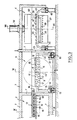
- the installation as shown in the appended figures for heating, forming and tempering glass sheets comprises an oven 1 for heating glass sheets, a suction chamber 2, a standard forming chamber 4, a deep forming chamber 5 and a quenching chamber 6. All of these chambers, with the exception of the quenching chamber, are heated to a temperature sufficient to maintain the glass sheets in a plastic state.
- the installation also includes means for supporting the glass sheets and moving them horizontally in the furnace 1 and towards said chambers 2 to 6.
- the installation further comprises, between the furnace 1 and the forming chambers 4 and 5, a turning chamber 3 comprising means for turning said sheets of glass.
- the furnace 1, the suction chamber 2, the turning chamber 3 and the standard forming chamber 4 are aligned, while the deep forming chamber 5 and the quench chamber 6 are located next to it. respectively the turning chamber 3 and the forming chamber 4. All the walls of these chambers are covered by a refractory lining 7.
- the means for turning the glass sheets 8 comprise a plate 9 rotatably mounted about an axis XX ′ in the turning chamber 3.
- This plate 9 is hollow and has on its two opposite faces 10, 11 a series of openings 12 distributed over all of these faces (see Figures 3 and 9).
- the interior of the plate 9 is connected by a pipe 9a (see fig. 6) to suction means such as a turbine not shown, to create a depression inside the plate 9, sufficient to press a sheet of glass 8 on the face 10 or 11 provided with openings 12.
- the plate 9 for turning the glass sheets 8 is supported by means making it possible to successively move the turned glass sheets 8 towards the deep forming chamber 5.
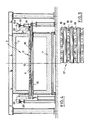
- Figures 2 and 3 show that inside the oven 1 and the suction chamber 2 is provided a series of parallel and rotating rollers 16 for supporting the glass sheets 8 (see Figure 2) and moving them horizontally towards the turning chamber 3 and / or towards the standard forming chamber 4 which is aligned with the heating oven 1.
- means are also provided for removing the glass sheets 8 from said rollers 16 in order to transfer them to the said chamber or chambers 3, 4.
- said means are suitable for sucking up the glass sheets 8.
- These means comprise (see FIGS. 2, 3, 4 and 5) a suction plate 17 movable in translation above the rollers 16 supporting the glass sheets 8 and parallel to these rollers 16.
- This plate is itself provided with rollers 18 located in a plane parallel to that of the rollers 16 supporting the glass sheets 8.
- the rollers 18 of the tray 17 protrude under the underside of this tray 17 and suction openings 19 are formed between the rollers 18 (see figure 5).
- the interior of the plate 17 is connected to a pipe 17a (FIG. 2) which is itself connected to a suction turbine not shown.
- rollers 18 carried by the plate 17 are rotated by pulleys 20 mounted at the end of their axis 21 and connected by a transmission member to a motor not shown.
- the length of the suction plate 17 measured in the direction of its movement exceeds that of the glass sheets 8.
- the turning plate 9 of the glass sheets 8 has a face 10 intended to receive the glass sheets 8, located in the extension of the rollers 16 supporting the sheets of glass, so that the suction plate 17 can pass over the turning plate 9, as shown in FIG. 3.
- the installation according to the invention comprises a standard forming chamber 4 and a deep forming chamber 5.
- the standard forming chamber 4 receives the glass sheets 8 in the position they occupy on the rollers 16 which support them, while the deep forming chamber 5 receives the sheets 8 in the inverted position, thanks to the turning plate 9.
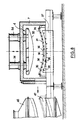
- the forming chambers 4 and 5 each comprise (see Figures 8 and 6) two forming surfaces 30, 31; 32, 33 movable towards each other. One of these surfaces is convex and the other is concave.
- the concave forming surface 31 is movable horizontally towards the quenching chamber 6 and the convex forming surface 30 is movable vertically towards the latter, by means of command 34.
- the concave forming surface 32 is movable horizontally towards the quenching chamber 6 and the convex forming surface 33 is movable vertically towards the latter (see arrow F on the figure 6).
- the concave forming surface 31 is located at the lower part of the chamber and comprises (see also FIG. 10) a hollow ring 35 intended to receive the sheet 8 to be formed and whose outline corresponds to that of the sheet in the formed state.
- This ring 35 has on its surface 31 intended to receive a glass sheet 8, a series of holes 36 communicating with the interior of this ring 35 which is connected by a pipe 35a (see FIG. 10) to suction means (not shown) to create a depression inside this ring 35.
- a body 37 having a series of holes 38 connected to means (not shown) for blowing hot air under a sheet of glass 8 resting on the 'ring 35.
- the horizontally movable concave forming surface 32 is located at the upper part of the chamber and comprises a hollow ring 39 intended to receive the sheet to be formed.
- the contour of this ring 39 corresponds to that of the sheet in the formed state and has on its surface 32 intended to receive the sheet, a series of holes 40 communicating with the interior of this ring 39 and with suction means. (not shown) to create a depression inside.
- the convex and vertically movable forming surface 33 located at the lower part of the deep forming chamber 5 has a peripheral rim intended to correspond to the contour of the sheet in the formed state which surrounds a cavity 50 having a series of holes 41 connected to means (not shown) for blowing hot air under the glass sheet, so as to prevent the glass sheet from collapsing.
- the flat glass sheets 8 resting on the rollers 16 are first heated in the oven 1 to a temperature between 600 and 700 ° C to make them suitable for subsequent forming.
- the heated sheets are then conveyed by the rotary rollers 16 to the suction chamber 2 which is also heated to a certain temperature to avoid any cooling of the glass sheets.
- the suction plate 17 is positioned above a glass sheet 8. When the suction means are started, the glass sheet is sucked towards the plate 17 located in the immediate vicinity of this sheet, so that the latter comes into slight contact against the rollers 18 of the suction plate 17.
- the plate 17 is moved on its raceway 23 directly to the chamber 4 for standard forming.
- the glass sheet 8 pressed under the suction plate 17 undergoes translation relative to this plate, by rotation of the rollers 18 against which the sheet 8 is in contact, which has the effect of 'avoid marking the glass sheet by contact with these rollers 18 and allow positioning of the glass sheet 8 above the ring 35 of the forming chamber 4.
- the speed of rotation of the rollers 18 will be relatively reduced so that the speed of movement of the sheet 8 relative to the plate is less than the speed of movement of this plate 17.
- the plate 17 brings the glass sheet 8 just above the ring 35 constituting the lower forming surface of the chamber 4.
- the convex forming surface 30 is lowered to adapt the forming profile of the glass sheet to that of the convex 30 and concave 31 surfaces.
- jets of hot air are sent, through the holes 38, to the lower surface of the sheet. 8 to maintain the latter at the desired temperature and to prevent it from deforming by gravity through the ring 35.
- the suction is interrupted so that the glass sheet 8 can be deposited on the upper face 10 of the plate 9.
- a vacuum is then produced at the inside of the plate 9 so as to press the sheet 8 on the top of this plate by suction.
- the rotation of the plate 9 is then controlled around its axis X-X ′ so as to turn it over 180 ° and the glass sheet 8 is located under the plate.
- the glass sheet 8 remains pressed under the tray due to the suction.
- the suction is cut off and the glass sheet 8 is deposited on the lower and convex forming surface 33.
- the turning plate 9 is then brought back to the turning chamber 3 to receive, after rotation of 180 °, a new sheet of glass 8.
- the forming surface 33 on which the glass sheet 8 rests moves upwards to apply the sheet against the ring 39 and thus form this sheet according to the profile of the surfaces 33 and 32.
- jets of hot air are sent to the sheet 8 through the holes 41 to prevent sagging of this sheet, while a vacuum is made in the ring 39 in order to press the periphery of the glass sheet 8 against the surface 32 of the ring 39 and thus avoid any lateral sliding of the sheet 8.
- the glass sheets 8 After the glass sheets 8 have been formed, either in the standard forming chamber 4 or in the deep forming chamber 5, the glass sheets 8 are successively moved towards the tempering chamber 6.
- the glass sheet 8 is placed (see FIG. 7) between two bodies 46, 47 having vertical channels 48, 49 which send on either side of the glass sheet 8 gaseous jets intended for the tempering of the glass sheet 8.
Landscapes
- Chemical & Material Sciences (AREA)
- Engineering & Computer Science (AREA)
- Materials Engineering (AREA)
- Organic Chemistry (AREA)
- Physics & Mathematics (AREA)
- Thermal Sciences (AREA)
- Re-Forming, After-Treatment, Cutting And Transporting Of Glass Products (AREA)
Applications Claiming Priority (2)
| Application Number | Priority Date | Filing Date | Title |
|---|---|---|---|
| FR9004097 | 1990-03-30 | ||
| FR9004097A FR2660302B1 (fr) | 1990-03-30 | 1990-03-30 | Installation pour le chauffage, le formage et la trempe de feuilles de verre. |
Publications (1)
| Publication Number | Publication Date |
|---|---|
| EP0451010A1 true EP0451010A1 (de) | 1991-10-09 |
Family
ID=9395290
Family Applications (1)
| Application Number | Title | Priority Date | Filing Date |
|---|---|---|---|
| EP91400787A Withdrawn EP0451010A1 (de) | 1990-03-30 | 1991-03-22 | Vorrichtung zum Beheizen, Formen und Tempern von Glastafeln |
Country Status (6)
| Country | Link |
|---|---|
| US (1) | US5160524A (de) |
| EP (1) | EP0451010A1 (de) |
| DE (1) | DE451010T1 (de) |
| ES (1) | ES2026439T1 (de) |
| FR (1) | FR2660302B1 (de) |
| GR (1) | GR910300138T1 (de) |
Cited By (3)
| Publication number | Priority date | Publication date | Assignee | Title |
|---|---|---|---|---|
| EP0520886A1 (de) * | 1991-06-27 | 1992-12-30 | Saint-Gobain Vitrage International | Verfahren und Vorrichtung zum Biegen einer Glasscheibe |
| EP0494823A3 (en) * | 1991-01-09 | 1993-08-04 | Saint-Gobain Vitrage International | Method and apparatus for treating hot glass sheets |
| KR101169658B1 (ko) * | 2002-11-08 | 2012-08-03 | 슈프레스타 엘엘씨 | 반응성 난연성 포스포네이트 올리고머 및 필러를 포함한에폭시 수지 조성물 |
Families Citing this family (4)
| Publication number | Priority date | Publication date | Assignee | Title |
|---|---|---|---|---|
| DE4215285C1 (de) * | 1992-05-09 | 1993-08-19 | Vegla Vereinigte Glaswerke Gmbh, 5100 Aachen, De | |
| US5320661A (en) * | 1992-07-02 | 1994-06-14 | Ppg Industries, Inc. | Method and apparatus of bending glass sheets |
| JP4027266B2 (ja) * | 2003-05-23 | 2007-12-26 | Hoya株式会社 | ガラス物品の徐冷方法、ガラス物品の加熱方法、ガラス成形品の製造方法、及び熱処理装置 |
| CN108793702B (zh) * | 2018-07-08 | 2021-11-02 | 威海烟华安全玻璃有限公司 | 一种玻璃生产用风冷型淬火装置 |
Citations (5)
| Publication number | Priority date | Publication date | Assignee | Title |
|---|---|---|---|---|
| US3665730A (en) * | 1970-06-11 | 1972-05-30 | Frederick D Linzer | Apparatus for simultaneously supporting, cooling and shaping glass sheet and the like |
| US3680677A (en) * | 1969-09-19 | 1972-08-01 | Pilkington Brothers Ltd | Conveying of glass sheets |
| US4711653A (en) * | 1986-12-29 | 1987-12-08 | Ppg Industries, Inc. | Innovative press bending of thermoplastic sheets |
| EP0267119A1 (de) * | 1986-11-06 | 1988-05-11 | Saint-Gobain Vitrage International | Biege/Härtevorrichtung für die Herstellung flacher oder gebogener Glasscheiben |
| EP0299869A1 (de) * | 1987-07-15 | 1989-01-18 | Saint-Gobain Vitrage International | Biegen von Glasscheiben |
Family Cites Families (3)
| Publication number | Priority date | Publication date | Assignee | Title |
|---|---|---|---|---|
| DE3407173C1 (de) * | 1984-02-28 | 1985-01-03 | Mannesmann AG, 4000 Düsseldorf | Anlage zum Herstellen von stark gekruemmten Glasscheiben |
| JPS6345138A (ja) * | 1986-08-08 | 1988-02-26 | Asahi Glass Co Ltd | ガラス板の曲げ加工方法 |
| DE68905703T2 (de) * | 1988-08-03 | 1993-07-08 | Nippon Sheet Glass Co Ltd | Vorrichtung zum biegen von glasscheiben. |
-
1990
- 1990-03-30 FR FR9004097A patent/FR2660302B1/fr not_active Expired - Fee Related
-
1991
- 1991-03-18 US US07/673,179 patent/US5160524A/en not_active Expired - Fee Related
- 1991-03-22 EP EP91400787A patent/EP0451010A1/de not_active Withdrawn
- 1991-03-22 ES ES199191400787T patent/ES2026439T1/es active Pending
- 1991-03-22 DE DE199191400787T patent/DE451010T1/de active Pending
-
1992
- 1992-06-30 GR GR91300138T patent/GR910300138T1/el unknown
Patent Citations (5)
| Publication number | Priority date | Publication date | Assignee | Title |
|---|---|---|---|---|
| US3680677A (en) * | 1969-09-19 | 1972-08-01 | Pilkington Brothers Ltd | Conveying of glass sheets |
| US3665730A (en) * | 1970-06-11 | 1972-05-30 | Frederick D Linzer | Apparatus for simultaneously supporting, cooling and shaping glass sheet and the like |
| EP0267119A1 (de) * | 1986-11-06 | 1988-05-11 | Saint-Gobain Vitrage International | Biege/Härtevorrichtung für die Herstellung flacher oder gebogener Glasscheiben |
| US4711653A (en) * | 1986-12-29 | 1987-12-08 | Ppg Industries, Inc. | Innovative press bending of thermoplastic sheets |
| EP0299869A1 (de) * | 1987-07-15 | 1989-01-18 | Saint-Gobain Vitrage International | Biegen von Glasscheiben |
Non-Patent Citations (1)
| Title |
|---|
| PATENT ABSTRACTS OF JAPAN, vol. 12, no. 258 (C-513)[3105] 20 juillet 1988; & JP-A-63 045 138 (ASAHI GLASS CO. LTD.) 26 février 1988, * |
Cited By (5)
| Publication number | Priority date | Publication date | Assignee | Title |
|---|---|---|---|---|
| EP0494823A3 (en) * | 1991-01-09 | 1993-08-04 | Saint-Gobain Vitrage International | Method and apparatus for treating hot glass sheets |
| EP0520886A1 (de) * | 1991-06-27 | 1992-12-30 | Saint-Gobain Vitrage International | Verfahren und Vorrichtung zum Biegen einer Glasscheibe |
| FR2678261A1 (fr) * | 1991-06-27 | 1992-12-31 | Saint Gobain Vitrage Int | Procede et dispositif de bombage d'une feuille de verre. |
| US5372624A (en) * | 1991-06-27 | 1994-12-13 | Saint-Gobain Vitrage International | Process and apparatus for bending a glass sheet |
| KR101169658B1 (ko) * | 2002-11-08 | 2012-08-03 | 슈프레스타 엘엘씨 | 반응성 난연성 포스포네이트 올리고머 및 필러를 포함한에폭시 수지 조성물 |
Also Published As
| Publication number | Publication date |
|---|---|
| ES2026439T1 (es) | 1992-05-01 |
| US5160524A (en) | 1992-11-03 |
| FR2660302A1 (fr) | 1991-10-04 |
| GR910300138T1 (en) | 1992-06-30 |
| DE451010T1 (de) | 1992-02-06 |
| FR2660302B1 (fr) | 1992-08-07 |
Similar Documents
| Publication | Publication Date | Title |
|---|---|---|
| EP0290346B1 (de) | Verfahren und Vorrichtung zum Biegen von Glasscheiben | |
| EP0241355B1 (de) | Glasscheibenbiegevorrichtung | |
| CA2031748C (fr) | Fabrication de vitrages sur une ligne comprenant plusieurs postes de travail | |
| CA2019486C (fr) | Procede et dispositif pour le bombage et la trempe par contact | |
| EP0556103A1 (de) | Vorrichtung zum Biegen von Windschutzscheiben | |
| FR2609017A1 (fr) | Appareil et procede de cambrage de feuilles, notamment de verre | |
| EP0474531B1 (de) | Verfahren und Vorrichtung zum Biegen von Glasscheiben | |
| EP1611064A2 (de) | Verfahren zum biegen von glasscheiben durch pressen und saugen | |
| FR2757149A1 (fr) | Dispositif et procede pour bomber des feuilles de verre | |
| WO2006075117A1 (fr) | Dispositif et procede de cintrage et de refroidissement de vitres a deux trains de supports | |
| WO2002006170A1 (fr) | Procede et dispositif de bombage d'une feuille de verre | |
| EP0839769A1 (de) | Verfahren und Vorrichtung zum progressiven Biegen von Glasscheibe | |
| EP0451010A1 (de) | Vorrichtung zum Beheizen, Formen und Tempern von Glastafeln | |
| FR2468557A1 (fr) | Dispositif d'alignement des moules pour installation de faconnage de feuilles de verre suivant des formes compliquees | |
| EP3281921A1 (de) | Verfahren und vorrichtung für den austausch der extraktionsrollen in einer ausfahrtschleuse eines zinnbads mit einem endlosträger des floatglas-bandes | |
| BE1000065A6 (fr) | Procede et appareil de cambrage de feuilles de verre. | |
| FR2609283A1 (fr) | Appareillage et procede pour profiler une feuille de verre ramollie par chauffage | |
| EP0389315B1 (de) | Positionierung einer Glasscheibe gegenüber Vorrichtungen zum Biegen und/oder für andere thermische Behandlungen | |
| FR2546503A1 (fr) | Support a depression a chambres multiples, utilise pour la mise en forme de feuilles de verre, avec des moyens d'isolement des chambres a vide voisines | |
| CA2005444C (fr) | Procede et dispositif d'obtention de vitrages automobiles bombes trempes | |
| EP1591425A1 (de) | Vorrichtung und Verfahren zum Formen einer Glasscheibe | |
| FR2516502A1 (fr) | Procede et dispositif pour extraire des feuilles de verre cintrees et trempees d'un poste de refroidissement | |
| EP0299869B1 (de) | Biegen von Glasscheiben | |
| FR2613710A1 (fr) | Appareil pour la fabrication de feuilles de verre cintrees | |
| EP0409695B1 (de) | Verfahren und Vorrichtung zum Herstellen von gebogenen oder/und emaillierten Glasscheiben |
Legal Events
| Date | Code | Title | Description |
|---|---|---|---|
| PUAI | Public reference made under article 153(3) epc to a published international application that has entered the european phase |
Free format text: ORIGINAL CODE: 0009012 |
|
| 17P | Request for examination filed |
Effective date: 19910327 |
|
| AK | Designated contracting states |
Kind code of ref document: A1 Designated state(s): AT BE CH DE DK ES GB GR IT LI LU NL SE |
|
| TCAT | At: translation of patent claims filed | ||
| ITCL | It: translation for ep claims filed |
Representative=s name: BARZANO' E ZANARDO ROMA S.P.A. |
|
| GBC | Gb: translation of claims filed (gb section 78(7)/1977) | ||
| TCNL | Nl: translation of patent claims filed | ||
| DET | De: translation of patent claims | ||
| REG | Reference to a national code |
Ref country code: ES Ref legal event code: BA2A Ref document number: 2026439 Country of ref document: ES Kind code of ref document: T1 |
|
| 17Q | First examination report despatched |
Effective date: 19930510 |
|
| STAA | Information on the status of an ep patent application or granted ep patent |
Free format text: STATUS: THE APPLICATION IS DEEMED TO BE WITHDRAWN |
|
| 18D | Application deemed to be withdrawn |
Effective date: 19940705 |