EP0451090A1 - Wiederbelebungs- und Beatmungsvorrichtung - Google Patents
Wiederbelebungs- und Beatmungsvorrichtung Download PDFInfo
- Publication number
- EP0451090A1 EP0451090A1 EP91810150A EP91810150A EP0451090A1 EP 0451090 A1 EP0451090 A1 EP 0451090A1 EP 91810150 A EP91810150 A EP 91810150A EP 91810150 A EP91810150 A EP 91810150A EP 0451090 A1 EP0451090 A1 EP 0451090A1
- Authority
- EP
- European Patent Office
- Prior art keywords
- valve
- gas
- flow
- chamber
- control valve
- Prior art date
- Legal status (The legal status is an assumption and is not a legal conclusion. Google has not performed a legal analysis and makes no representation as to the accuracy of the status listed.)
- Granted
Links
Images


Classifications
-
- A—HUMAN NECESSITIES
- A61—MEDICAL OR VETERINARY SCIENCE; HYGIENE
- A61M—DEVICES FOR INTRODUCING MEDIA INTO, OR ONTO, THE BODY; DEVICES FOR TRANSDUCING BODY MEDIA OR FOR TAKING MEDIA FROM THE BODY; DEVICES FOR PRODUCING OR ENDING SLEEP OR STUPOR
- A61M16/00—Devices for influencing the respiratory system of patients by gas treatment, e.g. ventilators; Tracheal tubes
Definitions
- one aspect of this invention relates to a flow control valve for use in devices for controlling a source of fluid.
- a flow control valve for use in devices for controlling a source of fluid.
- the present invention has particular application as a flow control valve for equipment such as inhalation devices, particular reference will be made to such devices in describing the present invention, although it is understood that the flow control valve may be used for various purposes, such as those described hereinafter.
- Masks for resuscitation where oxygen or gas is fed to a person for breathing and for inhalation, are known where a mixture of oxygen or gas and air or other gas is fed to a person, or primarily used by non-medical personnel, such as fire-fighters, police and ambulance personnel. Information concerning the person being treated is usually not available. Therefore, great care and attention is required to prevent a mishap from occurring, particularly in relation to the person being treated.
- the oxygen or gas, which is applied to the lungs of the person is usually supplied in containers of a relatively high pressure.
- a second valve is activated to allow a continuous feed of oxygen or gas.
- the oxygen or gas again flows passed the first, open valve to the chamber.
- the same control of maximum oxygen or gas pressure occurs by the movable valve member.
- the oxygen or gas then flows to a mixing chamber, where it mixes with air or a different gas and then flows to the face mask.
- one aspect of the present invention includes the feature that energy required to change the valve states is derived from the magnetic property of the valve with minor assist using a component associated with the magnetic valve, and operating in conjunction with the pressures in a variable pressure system.
- a flow control valve apparatus comprising a chamber; a valve member reciprocally mounted in the chamber; a flow control valve, acted upon by the valve member to an open position; means for connecting a high pressure source to an inlet of the valve; means for connecting a variable pressure volume to the chamber; means for selectively connecting a low pressure volume to the chamber; a first magnetic member on the valve member; a second magnetic member in spaced opposition to the first magnetic member; one of the first and second magnetic members being magnetized, to restrain movement of the valve member; the valve member being moved against the restrain when the variable pressure reaches a predetermined maximum value, to permit closing of the flow control valve, and to permit the connection of the low pressure volume to the chamber; and the valve member being moved with the restrain when the variable pressure reaches a predetermined low value, to open the flow control valve.
- a resuscitation and inhalation device comprising a first gaseous flow control valve, a movable valve member acted upon by the pressure of the first gas in a chamber, the movable valve member acting against an adjustable magnetic field, and alternate gaseous inlet valves for permitting flow of the first gas to the first gaseous flow control valve, operation of a first of the inlet valves permitting flow only when held in an actuated position and also, cutting off flow of a second gas to a mixing chamber in the device, operation of a second of the inlet valves permitting continuous flow of the first gas to the first gaseous flow control valve.
- the device has a variable magnetic distance - thus, the distance between the magnetic members is variable.
- the device preferably includes a housing, an annular seating member in the housing, the movable valve member being positioned in the annular seating member and seatable on a seat in the seating member, and with the seating member being movable to vary the distance between the magnetic members.
- the device includes an external sleeve on the housing and a screw thread between the sleeve and the housing, and means connecting the sleeve to the seating member, whereby rotation of the sleeve on the housing varies the distance between the magnetic members.
- the device includes an annular magnet in the housing, aligned with and spaced from the movable valve member, and having a flow control valve mounted for axial movement in the annular magnet.
- the device has a first oxygen or gaseous inlet valve which includes an operating member, and the operating member comprises mounting means, e.g., a button, slidable axially in a valve seating member, the first inlet valve comprising a ball valve and the mounting means or button including an extension for lifting the ball valve off its seating on movement of the button, and biasing means biasing the button to a non-operative position.
- the second inlet valve comprises a needle-valve.
- the device has a gaseous flow control valve which includes a stem and a head, the movable valve member acting on an end of the stem, and the head forming a seating at an end remote from the movable valve member.
- the device includes an inlet for supply of the gas to the alternate first and second gaseous inlet valves, and a control valve is mounted on the inlet for controlling gas flow therethrough, the control valve including a first flow passage open at all times for a predetermined minimum gas flow, and a second, openable flow passage for additional flow of gas to a predetermined maximum.
- the flow control device of the present invention can be housed in an appropriate housing of suitable material; for example, a housing of plastic or non-magnetic metallic material can be utilized.
- a housing of plastic or non-magnetic metallic material can be utilized.
- the housing will be substantially airtight and dustproof to prevent undesired particulate material from gaining access to the flow control valve.
- the device of the present invention permits adjustability of the gaseous flows, and comparing the device of the present invention to prior art devices which utilize springs for adjustment, the magnetic valve arrangement permits very specific and delicate adjustments when required.
- the device of the present invention will find use in various types of safety valves which require precise adjustments for exact control of gaseous flows.
- a primary safety feature of the present invention is that the valve releases under conditions where comparable spring-type valves would maintain pressure. Still further, the valves of the present invention are position-independent, compared to prior art systems.
- control valve of the present invention include use in clutch drives, permitting compensation for wear on a clutch plate, or in heat-activated systems where complete release under the operating environment is required.
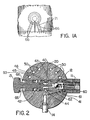
- the apparatus as illustrated in Figures 1, 2 and 3, is adapted to be mounted onto a conventional face mask (not shown), there being a connector 10 which connects by suitable means to the interior of the mask.
- Oxygen or gas is supplied to the apparatus at a connection 11.
- the apparatus comprises a main housing 20, in which is mounted an oxygen flow control valve 21, having a stem 22 and a head 23.
- the stem 22 has a somewhat triangular cross-section, with flats extending the length of the stem, so as to permit gaseous flow passed the stem 22.
- a Teflon (trade mark) member 24 holds an annular magnetic member 25, the valve stem 22 moving in an insert, for example, a Teflon insert 26.
- the head 23 forms a seating member for the valve 21.
- a chamber 27 Surrounding the member 24 is a chamber 27.
- valve member 30 moves in an adjustable seating member 31 which can be moved axially by rotation in the housing 20 to preset the distance between the magnetic metal member 29 and the magnetic member 25.
- a light spring 32 biases the valve member 30 down into contact with the seating 33 of the seating member 31.
- the bore of the insert 26 can have grooves extending along the bore, the stem 22 being cylindrical.
- the button 13 slides in a valve seating member 40 in which seats the valve 12, the valve 12 being biased against the seating 40 by a spring 41.
- the button 13 is biased to an outward position by a spring 42.
- the button 13 is limited in its movement by the effect on spring 42 by pin 71.
- the button 13 is pushed in, with a stem 43 at the inner end lifting valve 12 off its seating 40.
- Oxygen flows through connection 11, passed the valve 12, into chamber 44 and by passageway 45 and groove 46 and passageway 47 into the chamber 48 beneath the valve head 23 of the valve 21.
- oxygen flows up passed the stem 22 to the chamber 27. From the chamber 27, the oxygen flows through passageways 50, chamber 51, through filter 52 into the connector 10 and then to the face mask.
- the oxygen in the chamber 27 acts on the lower end of the valve member 30, and when the pressure in the chamber 27 reaches the maximum desired pressure, the valve member 30 moves up and allows valve 21 to close.
- the valve 21 closes under the action of the flow of oxygen from passageway 47. This will represent the end of the inhalation step of the patient.
- the patient then exhales, via the chamber 51, passageways 50, chamber 27, passed valve 30 via recesses 74, and out of vents 53, the air being deflected by deflector 54.
- valve member 30 is returned by spring 32, valve 21 is open and the sequence restarts.
- the pressure at which the valve member will start to move will depend upon the magnetic effect of the magnet 25 on the magnetic metal member 29. This can be determined by varying the distance between magnet 25 and magnetic metal member 29, and this obtained by the adjustable seating member 31.
- a controllable continuous flow of oxygen is provided by the valve 14.
- Oxygen flows from connector 11 through grooves 60 and 61, passageway 62, passed the valve seating member 40 and into the groove 46 through passageway 47 to the chamber 48. It then flows up passed valve 21, into chamber 27, and through passageways 50 to chamber 51.
- an annular seat 65 shuts off access to passageways 66, which otherwise permits air to enter chamber 51, and in addition, access to passageway 67 is cut off.
- the button 13 In the inhalation mode, the button 13 is in an outer position, thus air flows into chamber 51 to mix with the oxygen and flow to the connector 10, and also flows into the chamber 27.
- the passageways 66 are seen more clearly in Figure 1A and are also see in Figure 3.
- the adjustment of the seating member 31 is obtained by an exterior sleeve 70 rotationally connected to the housing 20 via the screw thread 71, and fixedly connected to the seating member 31, via screws 72. Rotation of the sleeve 70 relative to the housing 20 will move the sleeve up or down, depending upon the direction of rotation.
- the seating member 31, with the cap 73 and deflector 54, will move with the sleeve 70 as a unit. Movement of the seating member 31 will vary the distance, and thus the magnetic attraction, between magnet 25 and the member 29.
- valve 21 When the valve 21 is opened, flow occurs through the two bores 37, passed the head 23 and O-ring 39, and through the bores 38 into chamber 27.
- the valve stem 22 is guided in the bore 34.
- the number of bores 38 can vary, for example, three or more.
- the provision of the two bores 37 is to avoid any possible "jet" action through a single bore or similar passage holding the valve 21 shut.
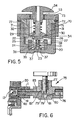
- FIG. 6 illustrates such a valve, indicated generally at 75, connected to the oxygen connection 11, the oxygen supply being connected to the valve 75 at inlet 76.
- the valve control member 77 has a central bore 78 at its lower end, with a cross-bore 79 spaced above the seating position of the control member 77. Bore 80 connects inlet 76 to a chamber 81 below the valve control member 77. When closed, the control member 77 seats on the upper periphery of the chamber 81, but a minimum flow still occurs through bores 78 and 79 to chamber 82 and thence via a bore 83 to the first valve 12 (see Figures 1, 2 and 6).
- the bores 78 and 79 control the minimum flow.
- the valve 75 controls the minimum flow of oxygen available at all times to the device and also the maximum flow which can be provided to the device.
- the various valves in the device actually control the flow of oxygen to the user.
- the minimum flow can be 40 litres per minute and the maximum flow, 90 litres per minute.
Landscapes
- Health & Medical Sciences (AREA)
- Emergency Medicine (AREA)
- Pulmonology (AREA)
- Engineering & Computer Science (AREA)
- Anesthesiology (AREA)
- Biomedical Technology (AREA)
- Heart & Thoracic Surgery (AREA)
- Hematology (AREA)
- Life Sciences & Earth Sciences (AREA)
- Animal Behavior & Ethology (AREA)
- General Health & Medical Sciences (AREA)
- Public Health (AREA)
- Veterinary Medicine (AREA)
- Respiratory Apparatuses And Protective Means (AREA)
- Air Humidification (AREA)
- Magnetically Actuated Valves (AREA)
Applications Claiming Priority (2)
| Application Number | Priority Date | Filing Date | Title |
|---|---|---|---|
| CA2011609 | 1990-03-06 | ||
| CA002011609A CA2011609C (en) | 1990-03-06 | 1990-03-06 | Resuscitation and inhalation device |
Publications (2)
| Publication Number | Publication Date |
|---|---|
| EP0451090A1 true EP0451090A1 (de) | 1991-10-09 |
| EP0451090B1 EP0451090B1 (de) | 1995-08-16 |
Family
ID=4144462
Family Applications (1)
| Application Number | Title | Priority Date | Filing Date |
|---|---|---|---|
| EP91810150A Expired - Lifetime EP0451090B1 (de) | 1990-03-06 | 1991-03-06 | Wiederbelebungs- und Beatmungsvorrichtung |
Country Status (6)
| Country | Link |
|---|---|
| US (1) | US5230330A (de) |
| EP (1) | EP0451090B1 (de) |
| AT (1) | ATE126447T1 (de) |
| CA (1) | CA2011609C (de) |
| DE (1) | DE69112106T2 (de) |
| ES (1) | ES2075400T3 (de) |
Families Citing this family (31)
| Publication number | Priority date | Publication date | Assignee | Title |
|---|---|---|---|---|
| EP0549299B1 (de) | 1991-12-20 | 2002-03-13 | Resmed Limited | Beatmungsgerät zur Erzeugung von kontinuierlichem positiven Atemwegdruck (CPAP) |
| DE69422900T2 (de) | 1993-12-01 | 2000-06-08 | Resmed Ltd., North Ryde | Vorrichtung zur Erzeugung eines kontinuierlichen positiven Atemwegdruckes (CPAP) |
| US5492115A (en) * | 1993-12-08 | 1996-02-20 | Abramov; Vladimir V. | Resuscitation breathing apparatus |
| US5398673A (en) * | 1993-12-10 | 1995-03-21 | Environmental Support Systems, Inc. | Resuscitator-snorkel for land or water use |
| US5632298A (en) * | 1995-03-17 | 1997-05-27 | Artinian; Hagop | Resuscitation and inhalation device |
| AUPN236595A0 (en) | 1995-04-11 | 1995-05-11 | Rescare Limited | Monitoring of apneic arousals |
| AUPN394895A0 (en) | 1995-07-03 | 1995-07-27 | Rescare Limited | Auto-calibration of pressure transducer offset |
| AUPN547895A0 (en) | 1995-09-15 | 1995-10-12 | Rescare Limited | Flow estimation and compenstion of flow-induced pressure swings cpap treatment |
| EP0862474A4 (de) | 1995-09-18 | 2000-05-03 | Resmed Ltd | Druckregelung bei cpap-behandlung oder bei assistierte beatmung |
| AUPN616795A0 (en) | 1995-10-23 | 1995-11-16 | Rescare Limited | Ipap duration in bilevel cpap or assisted respiration treatment |
| US5575279A (en) * | 1996-01-02 | 1996-11-19 | Emergency Filtration Products, Inc. | Dual-filtered rotary isolation valve for resusciation |
| AUPN973596A0 (en) | 1996-05-08 | 1996-05-30 | Resmed Limited | Control of delivery pressure in cpap treatment or assisted respiration |
| AUPO163896A0 (en) | 1996-08-14 | 1996-09-05 | Resmed Limited | Determination of respiratory airflow |
| AUPO247496A0 (en) | 1996-09-23 | 1996-10-17 | Resmed Limited | Assisted ventilation to match patient respiratory need |
| AUPO418696A0 (en) | 1996-12-12 | 1997-01-16 | Resmed Limited | A substance delivery apparatus |
| US5896857A (en) * | 1996-12-20 | 1999-04-27 | Resmed Limited | Valve for use in a gas delivery system |
| AUPO425696A0 (en) | 1996-12-18 | 1997-01-23 | Resmed Limited | A device for preventing or reducing the passage of air through the mouth |
| AUPO511397A0 (en) | 1997-02-14 | 1997-04-11 | Resmed Limited | An apparatus for varying the flow area of a conduit |
| EP1009464A4 (de) | 1997-05-16 | 2006-08-02 | Peter Craig Farrell | NASALE BEATMUNG ALS BEHANDLUNG VON Gehirnschlag. |
| AUPO742297A0 (en) | 1997-06-18 | 1997-07-10 | Resmed Limited | An apparatus for supplying breathable gas |
| US6067984A (en) * | 1997-10-14 | 2000-05-30 | Piper; Samuel David | Pulmonary modulator apparatus |
| AUPP015097A0 (en) | 1997-11-03 | 1997-11-27 | Resmed Limited | A mounting body |
| USD421298S (en) * | 1998-04-23 | 2000-02-29 | Resmed Limited | Flow generator |
| US6615831B1 (en) * | 1999-07-02 | 2003-09-09 | Respironics, Inc. | Pressure support system and method and a pressure control valve for use in such system and method |
| US6634357B1 (en) * | 2000-02-22 | 2003-10-21 | Life Support Technology, Inc. | Resuscitation valve assembly |
| US6792947B1 (en) * | 2000-08-25 | 2004-09-21 | O-Two Systems International Inc. | Flow control valve for manual resuscitator devices |
| US6612307B2 (en) * | 2000-09-11 | 2003-09-02 | Western/Scott Fetzer Company | Oxygen conserver |
| US20090014000A1 (en) * | 2007-07-13 | 2009-01-15 | Paul Robinson | Method and apparatus for hands free ventilation in a hazardous environment |
| US20090193567A1 (en) * | 2008-02-01 | 2009-08-06 | Treptow Christl D | Covering devices with warmer pockets |
| US8783251B2 (en) * | 2010-02-12 | 2014-07-22 | Piper Medical, Inc | Enhanced manually actuated pressure controlled modulator technology |
| WO2013159067A1 (en) * | 2012-04-20 | 2013-10-24 | Martin Bryan A | Magnetic field switches |
Citations (4)
| Publication number | Priority date | Publication date | Assignee | Title |
|---|---|---|---|---|
| US3853105A (en) * | 1971-12-16 | 1974-12-10 | P Kenagy | Insufflator gas flow device |
| US3931829A (en) * | 1973-06-29 | 1976-01-13 | Oxequip Health Industries | Valved service outlet |
| FR2276064A1 (fr) * | 1974-06-26 | 1976-01-23 | Masson Yves Le | Dispositif d'assistance respiratoire par relaxation de pression |
| US4006742A (en) * | 1973-12-27 | 1977-02-08 | Stephen Donald Flynn | Positive pressure resuscitator |
Family Cites Families (19)
| Publication number | Priority date | Publication date | Assignee | Title |
|---|---|---|---|---|
| CA887445A (en) * | 1971-12-07 | K. Wilson Robert | Positive pressure flow cut-off respiration system | |
| US402779A (en) * | 1889-05-07 | Emphysema | ||
| US2273790A (en) * | 1939-04-26 | 1942-02-17 | William H Stephenson | Mechanical resuscitator for combating asphyxia |
| US2364626A (en) * | 1942-11-09 | 1944-12-12 | John H Emerson | Resuscitator |
| DE1095469B (de) * | 1958-02-28 | 1960-12-22 | Draegerwerk Ag | Steuerung des Umschaltmechanismus von Vorrichtungen zur kuenstlichen Beatmung mit Hilfe von Magneten |
| US3209748A (en) * | 1963-04-19 | 1965-10-05 | Westinghouse Electric Corp | Reciprocating heart resuscitator device having fluid pressure control apparatus |
| US3351052A (en) * | 1965-10-18 | 1967-11-07 | Carl E Hewson | Heart and lung resuscitator |
| US3279487A (en) * | 1963-12-30 | 1966-10-18 | Roswell Park Memorial Hospital | Breathing valve |
| US3333581A (en) * | 1964-03-27 | 1967-08-01 | Elbert W Robinson | Pulmonary resuscitator with electrical control system |
| DE1273133B (de) * | 1965-11-22 | 1968-07-18 | Draegerwerk Ag | Beatmungsgeraet mit einem Aussenluft ansaugenden Injektor |
| US3581742A (en) * | 1968-06-11 | 1971-06-01 | Medical Services Inc | Intermittent positive pressure breathing device |
| US3610237A (en) * | 1968-10-07 | 1971-10-05 | Michigan Instr Inc | Inhalation positive pressure breathing apparatus |
| US4210174A (en) * | 1978-05-30 | 1980-07-01 | Instrumentation Industries, Inc. | Positive pressure valves |
| US4297999A (en) * | 1979-07-19 | 1981-11-03 | Kitrell John V | Portable resuscitation apparatus |
| US4349015A (en) * | 1980-11-14 | 1982-09-14 | Physio-Control Corporation | Manually-actuable CPR apparatus |
| DE3401383A1 (de) * | 1984-01-17 | 1985-07-25 | Drägerwerk AG, 2400 Lübeck | Atemschutzmaske mit ueberdruck im maskeninnenraum |
| DE3508130A1 (de) * | 1985-03-07 | 1986-09-11 | Drägerwerk AG, 2400 Lübeck | Lungengesteuertes ventil fuer atemschutzmasken mit ueberdruck im maskeninnenraum |
| DE3527174A1 (de) * | 1985-07-30 | 1987-02-12 | Bosch Gmbh Robert | Doppeltwirkendes magnetventil |
| US4825904A (en) * | 1988-04-18 | 1989-05-02 | Pneumo Abex Corporation | Two position flow control valve assembly with position sensing |
-
1990
- 1990-03-06 CA CA002011609A patent/CA2011609C/en not_active Expired - Lifetime
-
1991
- 1991-02-19 US US07/656,504 patent/US5230330A/en not_active Expired - Lifetime
- 1991-03-06 ES ES91810150T patent/ES2075400T3/es not_active Expired - Lifetime
- 1991-03-06 DE DE69112106T patent/DE69112106T2/de not_active Expired - Lifetime
- 1991-03-06 AT AT91810150T patent/ATE126447T1/de not_active IP Right Cessation
- 1991-03-06 EP EP91810150A patent/EP0451090B1/de not_active Expired - Lifetime
Patent Citations (4)
| Publication number | Priority date | Publication date | Assignee | Title |
|---|---|---|---|---|
| US3853105A (en) * | 1971-12-16 | 1974-12-10 | P Kenagy | Insufflator gas flow device |
| US3931829A (en) * | 1973-06-29 | 1976-01-13 | Oxequip Health Industries | Valved service outlet |
| US4006742A (en) * | 1973-12-27 | 1977-02-08 | Stephen Donald Flynn | Positive pressure resuscitator |
| FR2276064A1 (fr) * | 1974-06-26 | 1976-01-23 | Masson Yves Le | Dispositif d'assistance respiratoire par relaxation de pression |
Also Published As
| Publication number | Publication date |
|---|---|
| US5230330A (en) | 1993-07-27 |
| ATE126447T1 (de) | 1995-09-15 |
| ES2075400T3 (es) | 1995-10-01 |
| CA2011609C (en) | 1998-09-15 |
| CA2011609A1 (en) | 1991-09-06 |
| EP0451090B1 (de) | 1995-08-16 |
| DE69112106T2 (de) | 1996-01-11 |
| DE69112106D1 (de) | 1995-09-21 |
Similar Documents
| Publication | Publication Date | Title |
|---|---|---|
| US5230330A (en) | Resuscitation and inhalation device | |
| US5398714A (en) | Resuscitation and inhalation device | |
| US5632298A (en) | Resuscitation and inhalation device | |
| US4077404A (en) | Breathing equipment such as resuscitators | |
| US4436090A (en) | Piston actuated, pilot valve operated breathing regulator | |
| US4037595A (en) | Breathing equipment such as resuscitators | |
| JP4864976B2 (ja) | 飛行機用の呼吸マスク及び調整器の改良 | |
| US3068856A (en) | Fluid control device | |
| US3530890A (en) | Ventilating apparatus | |
| US4702240A (en) | Demand-responsive gas blending system for medical ventilator | |
| US5537999A (en) | Breathing apparatus | |
| US6634357B1 (en) | Resuscitation valve assembly | |
| US5241955A (en) | Breathing apparatus | |
| US3610237A (en) | Inhalation positive pressure breathing apparatus | |
| US3043302A (en) | Flow control unit for portable inhalators | |
| GB2079162A (en) | Resuscitator valve assembly | |
| KR0133496B1 (ko) | 유량조절 밸브장치 | |
| US3993095A (en) | Positive pressure resuscitator | |
| CA1153893A (en) | Metering valve | |
| GB2166360A (en) | Anaesthetic gas apparatus | |
| JP3270587B2 (ja) | 流体混合装置およびこの装置とともに用いて有用なデマンド弁 | |
| JP2764779B2 (ja) | 空気噴射特徴を有する呼吸調整器 | |
| KR100214158B1 (ko) | 양압식 공기호흡 시스템 | |
| JPS6345234B2 (de) | ||
| US3456643A (en) | Control system for breathing apparatus |
Legal Events
| Date | Code | Title | Description |
|---|---|---|---|
| PUAI | Public reference made under article 153(3) epc to a published international application that has entered the european phase |
Free format text: ORIGINAL CODE: 0009012 |
|
| AK | Designated contracting states |
Kind code of ref document: A1 Designated state(s): AT BE CH DE DK ES FR GB IT LI NL SE |
|
| 17P | Request for examination filed |
Effective date: 19920331 |
|
| 17Q | First examination report despatched |
Effective date: 19921202 |
|
| GRAA | (expected) grant |
Free format text: ORIGINAL CODE: 0009210 |
|
| AK | Designated contracting states |
Kind code of ref document: B1 Designated state(s): AT BE CH DE DK ES FR GB IT LI NL SE |
|
| PG25 | Lapsed in a contracting state [announced via postgrant information from national office to epo] |
Ref country code: DK Effective date: 19950816 Ref country code: NL Free format text: LAPSE BECAUSE OF FAILURE TO SUBMIT A TRANSLATION OF THE DESCRIPTION OR TO PAY THE FEE WITHIN THE PRESCRIBED TIME-LIMIT Effective date: 19950816 Ref country code: BE Effective date: 19950816 Ref country code: AT Effective date: 19950816 |
|
| REF | Corresponds to: |
Ref document number: 126447 Country of ref document: AT Date of ref document: 19950915 Kind code of ref document: T |
|
| REF | Corresponds to: |
Ref document number: 69112106 Country of ref document: DE Date of ref document: 19950921 |
|
| REG | Reference to a national code |
Ref country code: ES Ref legal event code: FG2A Ref document number: 2075400 Country of ref document: ES Kind code of ref document: T3 |
|
| ET | Fr: translation filed | ||
| ITF | It: translation for a ep patent filed | ||
| PG25 | Lapsed in a contracting state [announced via postgrant information from national office to epo] |
Ref country code: SE Effective date: 19951116 |
|
| NLV1 | Nl: lapsed or annulled due to failure to fulfill the requirements of art. 29p and 29m of the patents act | ||
| PLBE | No opposition filed within time limit |
Free format text: ORIGINAL CODE: 0009261 |
|
| 26N | No opposition filed | ||
| PGFP | Annual fee paid to national office [announced via postgrant information from national office to epo] |
Ref country code: FR Payment date: 19980325 Year of fee payment: 8 |
|
| PGFP | Annual fee paid to national office [announced via postgrant information from national office to epo] |
Ref country code: ES Payment date: 19980326 Year of fee payment: 8 |
|
| PGFP | Annual fee paid to national office [announced via postgrant information from national office to epo] |
Ref country code: CH Payment date: 19980609 Year of fee payment: 8 |
|
| PG25 | Lapsed in a contracting state [announced via postgrant information from national office to epo] |
Ref country code: ES Free format text: LAPSE BECAUSE OF NON-PAYMENT OF DUE FEES Effective date: 19990308 |
|
| PG25 | Lapsed in a contracting state [announced via postgrant information from national office to epo] |
Ref country code: CH Free format text: LAPSE BECAUSE OF NON-PAYMENT OF DUE FEES Effective date: 19990331 Ref country code: LI Free format text: LAPSE BECAUSE OF NON-PAYMENT OF DUE FEES Effective date: 19990331 |
|
| REG | Reference to a national code |
Ref country code: CH Ref legal event code: PL |
|
| PG25 | Lapsed in a contracting state [announced via postgrant information from national office to epo] |
Ref country code: FR Free format text: LAPSE BECAUSE OF NON-PAYMENT OF DUE FEES Effective date: 19991130 |
|
| REG | Reference to a national code |
Ref country code: FR Ref legal event code: ST |
|
| REG | Reference to a national code |
Ref country code: ES Ref legal event code: FD2A Effective date: 20010503 |
|
| REG | Reference to a national code |
Ref country code: GB Ref legal event code: IF02 |
|
| PG25 | Lapsed in a contracting state [announced via postgrant information from national office to epo] |
Ref country code: IT Free format text: LAPSE BECAUSE OF NON-PAYMENT OF DUE FEES;WARNING: LAPSES OF ITALIAN PATENTS WITH EFFECTIVE DATE BEFORE 2007 MAY HAVE OCCURRED AT ANY TIME BEFORE 2007. THE CORRECT EFFECTIVE DATE MAY BE DIFFERENT FROM THE ONE RECORDED. Effective date: 20050306 |
|
| PGFP | Annual fee paid to national office [announced via postgrant information from national office to epo] |
Ref country code: GB Payment date: 20100303 Year of fee payment: 20 |
|
| PGFP | Annual fee paid to national office [announced via postgrant information from national office to epo] |
Ref country code: DE Payment date: 20100318 Year of fee payment: 20 |
|
| REG | Reference to a national code |
Ref country code: DE Ref legal event code: R071 Ref document number: 69112106 Country of ref document: DE |
|
| REG | Reference to a national code |
Ref country code: GB Ref legal event code: PE20 Expiry date: 20110305 |
|
| PG25 | Lapsed in a contracting state [announced via postgrant information from national office to epo] |
Ref country code: GB Free format text: LAPSE BECAUSE OF EXPIRATION OF PROTECTION Effective date: 20110305 |
|
| PG25 | Lapsed in a contracting state [announced via postgrant information from national office to epo] |
Ref country code: DE Free format text: LAPSE BECAUSE OF EXPIRATION OF PROTECTION Effective date: 20110306 |