EP0451097A2 - Dispositif de chauffage réglé par thermostat pour une douche anale d'une toilette - Google Patents
Dispositif de chauffage réglé par thermostat pour une douche anale d'une toilette Download PDFInfo
- Publication number
- EP0451097A2 EP0451097A2 EP91810200A EP91810200A EP0451097A2 EP 0451097 A2 EP0451097 A2 EP 0451097A2 EP 91810200 A EP91810200 A EP 91810200A EP 91810200 A EP91810200 A EP 91810200A EP 0451097 A2 EP0451097 A2 EP 0451097A2
- Authority
- EP
- European Patent Office
- Prior art keywords
- water
- heating device
- inlet
- insert
- outlet
- Prior art date
- Legal status (The legal status is an assumption and is not a legal conclusion. Google has not performed a legal analysis and makes no representation as to the accuracy of the status listed.)
- Granted
Links
Images

Classifications
-
- F—MECHANICAL ENGINEERING; LIGHTING; HEATING; WEAPONS; BLASTING
- F24—HEATING; RANGES; VENTILATING
- F24H—FLUID HEATERS, e.g. WATER OR AIR HEATERS, HAVING HEAT-GENERATING MEANS, e.g. HEAT PUMPS, IN GENERAL
- F24H1/00—Water heaters, e.g. boilers, continuous-flow heaters or water-storage heaters
- F24H1/18—Water-storage heaters
- F24H1/20—Water-storage heaters with immersed heating elements, e.g. electric elements or furnace tubes
- F24H1/201—Water-storage heaters with immersed heating elements, e.g. electric elements or furnace tubes using electric energy supply
- F24H1/202—Water-storage heaters with immersed heating elements, e.g. electric elements or furnace tubes using electric energy supply with resistances
-
- E—FIXED CONSTRUCTIONS
- E03—WATER SUPPLY; SEWERAGE
- E03D—WATER-CLOSETS OR URINALS WITH FLUSHING DEVICES; FLUSHING VALVES THEREFOR
- E03D9/00—Sanitary or other accessories for lavatories ; Devices for cleaning or disinfecting the toilet room or the toilet bowl; Devices for eliminating smells
- E03D9/08—Devices in the bowl producing upwardly-directed sprays; Modifications of the bowl for use with such devices ; Bidets; Combinations of bowls with urinals or bidets; Hot-air or other devices mounted in or on the bowl, urinal or bidet for cleaning or disinfecting
Definitions
- the invention relates to a heating device according to the preamble of independent claim 1.
- Heating devices also called hot water storage tanks or boilers
- cold water enters an inner boiler through an inlet pipe at the bottom and the hot water is forced to drain through an outlet attached to the upper end of the inner boiler.
- a heating device has become known from CH-A 597 447, which has a heating room in which the incoming cold water is heated in the manner of a immersion heater and a downstream storage room in which the heated shower water is kept ready for use.
- This subdivision of the interior of the heating facility an even water temperature in the storage room should be ensured.
- the storage room and the heating room are divided by a horizontal pipe section that allows the water to flow counter-current. Accordingly, the outlet of the water from the storage room and the inlet of the cold water are located on the same side of the pipe section.
- This heating device has a cylindrical outer shape and is therefore suitable for installation in a corresponding tubular installation element, in which the further devices for the shower are housed and which is mounted in the hollow attachment of the toilet seat.
- the external shape is largely determined by the structure mentioned above.
- Toilet seats with such a heating device accordingly have a comparatively high approach, which often does not do justice to today's facilities in terms of aesthetics.
- a toilet seat with a larger and flatter upper side and a correspondingly lower attachment would be desirable.
- the object of the invention is to create a heating device which has fewer restrictions with regard to the external shape and which is nevertheless suitable for a shower in a water closet.
- the object is achieved by the invention according to claim 1.
- the water flowing into the interior of the housing with network pressure is largely calmed down immediately after the inlet. Without a subdivision into a heating room and a storage room, uniform heating of the water to the desired body temperature can be achieved in a comparatively short flow path.
- both the water inlet and the water outlet are arranged in the upper region of the housing in the device according to the invention.
- the inflowing cold water essentially flows from top to bottom and the warm water from bottom to top to the outlet.
- the interior and, accordingly, the outer shape of the heating device can largely be chosen freely. In particular, a drop-shaped cross section and a lower height of the housing of the heating device are possible, which is particularly advantageous with regard to the shape of the toilet seat.
- a particularly effective calming of the inflowing cold water is achieved if, according to a development of the invention, an insert with a horizontal plate is provided in the interior of the housing, this horizontally extending plate having holes for the passage of the water flowing downwards. The effect of sedation is increased even more when this plate is after has projections directed above.
- the insert has upwardly directed webs, on which a partition is arranged at a distance from the plate, which deflects the inflowing cold water upwards against the housing.
- the cold water flows upwards for a short time immediately after the inlet and is then deflected downwards through the housing wall. This measure also helps to quickly calm the water flowing in at high pressure and a comparatively high speed.
- the thermostat is a capillary tube thermostat and this is arranged above the heating element. Tests have shown that this arrangement achieves a very good temperature characteristic despite the unconventional design. Further advantageous features result from the remaining dependent claims and the following description.
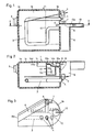
- the heating device has a thermally well-insulating plastic housing 1 made of a cover 1a and a housing body 1b.
- the cover 1 a has a fuse 5 known per se and is tightly connected to the body 1 on all sides by means of vibration welding.
- a heating rod 3 bent into a flat loop and a capillary tube thermostat 2 are used, which are fastened to the housing body 1b and which are connected to the outside of the housing in a manner known per se with electrical control and supply lines 4 and 12.
- the heating element 3 is arranged in the lower region of the cavity 1e and the thermostat 2 is located above this heating element 3.
- connection 13 For the supply of the cold water, a connection 13 is provided, which is integrally formed on an overflow channel 8 molded onto a housing body 1b. 3, this channel 8 leads downward and with an opening 8a to the outside.
- a pipe interrupter 9 which is formed in a manner known per se by a free path between the mouth 13a of the connection part 13 and a water inlet opening 6. The minimum length of this route is usually prescribed.
- the pipe interrupter prevents water from getting into the water supply network from the interior 1e. In such a case, only air is drawn through the opening 8a into the water supply network.
- the pipe interrupter 9 also forms an overflow protection here.
- the upper region of the cavity 1e is connected to the outside air, so that no dangerous excess pressure can build up in this space 1e.
- a pipe interrupter and an overflow protection device are thus advantageously produced.
- the course of the inflowing cold water through the opening 6 is indicated in FIGS. 2 and 5 by the arrows 14a, 14b and 14c. With the help of an insert 10, this flow pattern leads to rapid calming of the inflowing water.
- the water flowing through the opening 6 horizontally into a prechamber 10a arranged in the upper part of space 1e, in which the water is deflected upwards in the direction of arrow 14b and laterally to the left and right in the direction of arrows 14b.
- This direction of flow is significantly influenced by a partition 10g of the insert 10 and by the housing body 1b.
- the already partially calmed water then flows downwards in the direction of the arrows 14c against a plate 10d of the insert 10 which has a plurality of passages 10e and ribs 10f projecting upwards.
- These projections 10f and passages 10e calm the water so that it flows down below the plate 10d at a low speed and is heated by the heating element 3.
- the heated water passes through the natural buoyancy upwards and approximately in the direction of arrow 14d (FIG. 2) along a wall 1c to an outlet opening 7, from which the heated water reaches a shower arm via a hose line, not shown here.
- the wall 1c is integrally formed on the housing 1 and ensures that in the region of the two openings 6 and 7 the heated outflowing water is separated from the inflowing cold water.
- the insert 10 shown in FIGS. 5 and 6 is made as a separate piece of plastic and is inserted into the housing body 1b before the cover 1a is placed on it, with supports 1d on the housing body 1b having this insert 10 hold.
- the partition 10g is connected to the plate 10d via two parallel webs 10c.
- a passage 10b can be provided in the wall 10g, through which water can likewise get down from the chamber 10a to the radiator 3.
- the heating device can of course also have a temperature limit, not shown here.
- the entire cavity 1e is at the same time the boiler room and the storage room. In the case of small external dimensions, a comparatively large amount of warm flow water can be kept in stock.
Landscapes
- Engineering & Computer Science (AREA)
- Public Health (AREA)
- Health & Medical Sciences (AREA)
- Epidemiology (AREA)
- Hydrology & Water Resources (AREA)
- Mechanical Engineering (AREA)
- General Engineering & Computer Science (AREA)
- Chemical & Material Sciences (AREA)
- Molecular Biology (AREA)
- Thermal Sciences (AREA)
- Physics & Mathematics (AREA)
- Life Sciences & Earth Sciences (AREA)
- Combustion & Propulsion (AREA)
- Water Supply & Treatment (AREA)
- Instantaneous Water Boilers, Portable Hot-Water Supply Apparatuses, And Control Of Portable Hot-Water Supply Apparatuses (AREA)
- Bidet-Like Cleaning Device And Other Flush Toilet Accessories (AREA)
- Heat-Pump Type And Storage Water Heaters (AREA)
- Steam Or Hot-Water Central Heating Systems (AREA)
- Sanitary Device For Flush Toilet (AREA)
- Domestic Plumbing Installations (AREA)
- Steroid Compounds (AREA)
Applications Claiming Priority (2)
| Application Number | Priority Date | Filing Date | Title |
|---|---|---|---|
| CH1108/90 | 1990-04-03 | ||
| CH110890 | 1990-04-03 |
Publications (3)
| Publication Number | Publication Date |
|---|---|
| EP0451097A2 true EP0451097A2 (fr) | 1991-10-09 |
| EP0451097A3 EP0451097A3 (en) | 1992-10-21 |
| EP0451097B1 EP0451097B1 (fr) | 1995-04-19 |
Family
ID=4202682
Family Applications (1)
| Application Number | Title | Priority Date | Filing Date |
|---|---|---|---|
| EP91810200A Expired - Lifetime EP0451097B1 (fr) | 1990-04-03 | 1991-03-22 | Dispositif de chauffage réglé par thermostat pour une douche anale d'une toilette |
Country Status (7)
| Country | Link |
|---|---|
| US (1) | US5206928A (fr) |
| EP (1) | EP0451097B1 (fr) |
| AT (1) | ATE121483T1 (fr) |
| CA (1) | CA2038856A1 (fr) |
| DE (2) | DE9103209U1 (fr) |
| FI (1) | FI911483L (fr) |
| NO (1) | NO911182L (fr) |
Families Citing this family (4)
| Publication number | Priority date | Publication date | Assignee | Title |
|---|---|---|---|---|
| US5377300A (en) * | 1992-11-04 | 1994-12-27 | Watkins-Johnson Company | Heater for processing gases |
| US6148146A (en) * | 1998-01-07 | 2000-11-14 | Poore; Bobby L. | Water heater |
| US8303665B2 (en) * | 2004-06-15 | 2012-11-06 | Tornier Sas | Glenoidal component, set of such components and shoulder prosthesis incorporating such a glenoidal component |
| WO2014018564A1 (fr) | 2012-07-23 | 2014-01-30 | Zieger Claus Dieter | Procédés et système de répartition de proportions multiples |
Citations (1)
| Publication number | Priority date | Publication date | Assignee | Title |
|---|---|---|---|---|
| CH597447A5 (fr) | 1975-06-14 | 1978-04-14 | Gaggenau Werke |
Family Cites Families (5)
| Publication number | Priority date | Publication date | Assignee | Title |
|---|---|---|---|---|
| US3462766A (en) * | 1966-11-17 | 1969-08-26 | Mentor Inc | Hygienic spray device for toilets |
| US3638619A (en) * | 1970-06-17 | 1972-02-01 | Itt | Thermostatically controlled liquid-heating tank |
| JPS56150240A (en) * | 1980-04-21 | 1981-11-20 | Aisin Seiki | Automatic limited part washing apparatus of stool |
| US4559651A (en) * | 1983-12-20 | 1985-12-24 | Matsushita Electric Industrial Co., Ltd. | Hot-water washing apparatus for personal hygiene |
| JP2545843B2 (ja) * | 1987-03-30 | 1996-10-23 | アイシン精機株式会社 | 人体局部洗浄装置の水回路 |
-
1991
- 1991-03-15 DE DE9103209U patent/DE9103209U1/de not_active Expired - Lifetime
- 1991-03-22 AT AT91810200T patent/ATE121483T1/de active
- 1991-03-22 EP EP91810200A patent/EP0451097B1/fr not_active Expired - Lifetime
- 1991-03-22 CA CA002038856A patent/CA2038856A1/fr not_active Abandoned
- 1991-03-22 DE DE59105217T patent/DE59105217D1/de not_active Expired - Fee Related
- 1991-03-25 NO NO91911182A patent/NO911182L/no unknown
- 1991-03-27 FI FI911483A patent/FI911483L/fi not_active Application Discontinuation
- 1991-04-02 US US07/679,289 patent/US5206928A/en not_active Expired - Fee Related
Patent Citations (1)
| Publication number | Priority date | Publication date | Assignee | Title |
|---|---|---|---|---|
| CH597447A5 (fr) | 1975-06-14 | 1978-04-14 | Gaggenau Werke |
Also Published As
| Publication number | Publication date |
|---|---|
| FI911483A7 (fi) | 1991-10-04 |
| DE59105217D1 (de) | 1995-05-24 |
| NO911182D0 (no) | 1991-03-25 |
| EP0451097B1 (fr) | 1995-04-19 |
| FI911483L (fi) | 1991-10-04 |
| US5206928A (en) | 1993-04-27 |
| FI911483A0 (fi) | 1991-03-27 |
| CA2038856A1 (fr) | 1991-10-04 |
| DE9103209U1 (de) | 1991-06-13 |
| ATE121483T1 (de) | 1995-05-15 |
| EP0451097A3 (en) | 1992-10-21 |
| NO911182L (no) | 1991-10-04 |
Similar Documents
| Publication | Publication Date | Title |
|---|---|---|
| DE60006296T2 (de) | Dampferzeuger für Reinigungsmaschinen, Bügeleisen, Kaffemaschinen und ähnliche Maschinen | |
| EP0193863B1 (fr) | Générateur de vapeur, en particulier pour appareils de cuisson | |
| EP0451097B1 (fr) | Dispositif de chauffage réglé par thermostat pour une douche anale d'une toilette | |
| EP0083358A1 (fr) | Installation de remplissage automatique de cellules de batterie. | |
| DE4132351C2 (de) | Warmwasserkasten für eine Unterdusche | |
| DE2241763A1 (de) | Einlaufgarnitur fuer spuelkaesten | |
| EP3848520A1 (fr) | Soupape de vidange d'eau à vitesse de sortie réglable | |
| AT392339B (de) | Gehaeuse fuer eine wand-bademischbatterie | |
| AT411394B (de) | Rohrheizkörper | |
| AT396292B (de) | Gas-wasserheizer | |
| DE1778029A1 (de) | Warmwasser-Zentralheizungsanlage fuer mehrere Stockwerke | |
| DE8135167U1 (de) | Vorrichtung zum regulieren eines fluessigkeitsdurchflusses | |
| DE3009367A1 (de) | Warmwasserbereiter mit einem liegenden behaelter | |
| DE3502435A1 (de) | Heizungskessel | |
| DE1579842C3 (de) | Heizkörper-AnschluBvorrichtung für eine Zentralheizungsanlage | |
| AT359241B (de) | Vorrichtung zur automatischen speisung mindestens eines wasserbehaelters fuer die luft- befeuchtung | |
| DE2642911B2 (fr) | ||
| DE1803030C (de) | Mischbatterie mit einer Druckausgleichseinrichtung | |
| DE1565189B2 (de) | Elektrisch beheizter Durchlauferhitzer für Warmwasserraumheizung | |
| DE2058329C (de) | Heißwasser Regelarmatur | |
| DE2361952C3 (de) | Umwälzpumpe für Warmwasser-Heizungsanlagen | |
| AT257108B (de) | Lüftgerät | |
| AT400931B (de) | Düse für ein wannensprudelbad | |
| DE525373C (de) | Durchflusssperre fuer Leichtfluessigkeitsabscheider | |
| DE1417541A1 (de) | Entgaser fuer Wasser |
Legal Events
| Date | Code | Title | Description |
|---|---|---|---|
| PUAI | Public reference made under article 153(3) epc to a published international application that has entered the european phase |
Free format text: ORIGINAL CODE: 0009012 |
|
| AK | Designated contracting states |
Kind code of ref document: A2 Designated state(s): AT BE CH DE DK ES FR GB IT LI LU NL SE |
|
| PUAL | Search report despatched |
Free format text: ORIGINAL CODE: 0009013 |
|
| AK | Designated contracting states |
Kind code of ref document: A3 Designated state(s): AT BE CH DE DK ES FR GB IT LI LU NL SE |
|
| 17P | Request for examination filed |
Effective date: 19921110 |
|
| 17Q | First examination report despatched |
Effective date: 19940630 |
|
| GRAA | (expected) grant |
Free format text: ORIGINAL CODE: 0009210 |
|
| AK | Designated contracting states |
Kind code of ref document: B1 Designated state(s): AT BE CH DE DK ES FR GB IT LI LU NL SE |
|
| PG25 | Lapsed in a contracting state [announced via postgrant information from national office to epo] |
Ref country code: ES Free format text: THE PATENT HAS BEEN ANNULLED BY A DECISION OF A NATIONAL AUTHORITY Effective date: 19950419 Ref country code: DK Effective date: 19950419 |
|
| REF | Corresponds to: |
Ref document number: 121483 Country of ref document: AT Date of ref document: 19950515 Kind code of ref document: T |
|
| ITF | It: translation for a ep patent filed | ||
| REF | Corresponds to: |
Ref document number: 59105217 Country of ref document: DE Date of ref document: 19950524 |
|
| ET | Fr: translation filed | ||
| PG25 | Lapsed in a contracting state [announced via postgrant information from national office to epo] |
Ref country code: SE Effective date: 19950719 |
|
| GBT | Gb: translation of ep patent filed (gb section 77(6)(a)/1977) |
Effective date: 19950630 |
|
| PGFP | Annual fee paid to national office [announced via postgrant information from national office to epo] |
Ref country code: FR Payment date: 19960208 Year of fee payment: 6 |
|
| PGFP | Annual fee paid to national office [announced via postgrant information from national office to epo] |
Ref country code: BE Payment date: 19960216 Year of fee payment: 6 |
|
| PLBE | No opposition filed within time limit |
Free format text: ORIGINAL CODE: 0009261 |
|
| PG25 | Lapsed in a contracting state [announced via postgrant information from national office to epo] |
Ref country code: GB Effective date: 19960322 |
|
| PGFP | Annual fee paid to national office [announced via postgrant information from national office to epo] |
Ref country code: NL Payment date: 19960329 Year of fee payment: 6 |
|
| PG25 | Lapsed in a contracting state [announced via postgrant information from national office to epo] |
Ref country code: LU Free format text: LAPSE BECAUSE OF NON-PAYMENT OF DUE FEES Effective date: 19960331 |
|
| 26N | No opposition filed | ||
| GBPC | Gb: european patent ceased through non-payment of renewal fee |
Effective date: 19960322 |
|
| PG25 | Lapsed in a contracting state [announced via postgrant information from national office to epo] |
Ref country code: BE Effective date: 19970331 |
|
| BERE | Be: lapsed |
Owner name: GEBERIT A.G. Effective date: 19970331 |
|
| PG25 | Lapsed in a contracting state [announced via postgrant information from national office to epo] |
Ref country code: NL Effective date: 19971001 |
|
| PG25 | Lapsed in a contracting state [announced via postgrant information from national office to epo] |
Ref country code: FR Free format text: LAPSE BECAUSE OF NON-PAYMENT OF DUE FEES Effective date: 19971128 |
|
| NLV4 | Nl: lapsed or anulled due to non-payment of the annual fee |
Effective date: 19971001 |
|
| REG | Reference to a national code |
Ref country code: FR Ref legal event code: ST |
|
| PGFP | Annual fee paid to national office [announced via postgrant information from national office to epo] |
Ref country code: CH Payment date: 20010118 Year of fee payment: 11 |
|
| PGFP | Annual fee paid to national office [announced via postgrant information from national office to epo] |
Ref country code: AT Payment date: 20010207 Year of fee payment: 11 |
|
| PGFP | Annual fee paid to national office [announced via postgrant information from national office to epo] |
Ref country code: DE Payment date: 20010222 Year of fee payment: 11 |
|
| PG25 | Lapsed in a contracting state [announced via postgrant information from national office to epo] |
Ref country code: AT Free format text: LAPSE BECAUSE OF NON-PAYMENT OF DUE FEES Effective date: 20020322 |
|
| PG25 | Lapsed in a contracting state [announced via postgrant information from national office to epo] |
Ref country code: LI Free format text: LAPSE BECAUSE OF NON-PAYMENT OF DUE FEES Effective date: 20020331 Ref country code: CH Free format text: LAPSE BECAUSE OF NON-PAYMENT OF DUE FEES Effective date: 20020331 |
|
| PG25 | Lapsed in a contracting state [announced via postgrant information from national office to epo] |
Ref country code: DE Free format text: LAPSE BECAUSE OF NON-PAYMENT OF DUE FEES Effective date: 20021001 |
|
| REG | Reference to a national code |
Ref country code: CH Ref legal event code: PL |
|
| PG25 | Lapsed in a contracting state [announced via postgrant information from national office to epo] |
Ref country code: IT Free format text: LAPSE BECAUSE OF NON-PAYMENT OF DUE FEES;WARNING: LAPSES OF ITALIAN PATENTS WITH EFFECTIVE DATE BEFORE 2007 MAY HAVE OCCURRED AT ANY TIME BEFORE 2007. THE CORRECT EFFECTIVE DATE MAY BE DIFFERENT FROM THE ONE RECORDED. Effective date: 20050322 |