EP0451116B1 - Verbesserte Teleskopdoppelschieldbohrmaschine - Google Patents
Verbesserte Teleskopdoppelschieldbohrmaschine Download PDFInfo
- Publication number
- EP0451116B1 EP0451116B1 EP91830113A EP91830113A EP0451116B1 EP 0451116 B1 EP0451116 B1 EP 0451116B1 EP 91830113 A EP91830113 A EP 91830113A EP 91830113 A EP91830113 A EP 91830113A EP 0451116 B1 EP0451116 B1 EP 0451116B1
- Authority
- EP
- European Patent Office
- Prior art keywords
- shield
- boring machine
- respect
- machine according
- anyone
- Prior art date
- Legal status (The legal status is an assumption and is not a legal conclusion. Google has not performed a legal analysis and makes no representation as to the accuracy of the status listed.)
- Expired - Lifetime
Links
- 230000033001 locomotion Effects 0.000 claims abstract description 4
- 230000008878 coupling Effects 0.000 claims description 10
- 238000010168 coupling process Methods 0.000 claims description 10
- 238000005859 coupling reaction Methods 0.000 claims description 10
- 238000004140 cleaning Methods 0.000 claims description 3
- 230000002093 peripheral effect Effects 0.000 claims description 2
- NMFHJNAPXOMSRX-PUPDPRJKSA-N [(1r)-3-(3,4-dimethoxyphenyl)-1-[3-(2-morpholin-4-ylethoxy)phenyl]propyl] (2s)-1-[(2s)-2-(3,4,5-trimethoxyphenyl)butanoyl]piperidine-2-carboxylate Chemical compound C([C@@H](OC(=O)[C@@H]1CCCCN1C(=O)[C@@H](CC)C=1C=C(OC)C(OC)=C(OC)C=1)C=1C=C(OCCN2CCOCC2)C=CC=1)CC1=CC=C(OC)C(OC)=C1 NMFHJNAPXOMSRX-PUPDPRJKSA-N 0.000 description 13
- 238000005452 bending Methods 0.000 description 4
- 230000000903 blocking effect Effects 0.000 description 2
- 238000006243 chemical reaction Methods 0.000 description 2
- 239000011435 rock Substances 0.000 description 2
- 238000010008 shearing Methods 0.000 description 2
- XLYOFNOQVPJJNP-UHFFFAOYSA-N water Substances O XLYOFNOQVPJJNP-UHFFFAOYSA-N 0.000 description 2
- 238000009412 basement excavation Methods 0.000 description 1
- 230000005540 biological transmission Effects 0.000 description 1
- 238000005516 engineering process Methods 0.000 description 1
- 230000008595 infiltration Effects 0.000 description 1
- 238000001764 infiltration Methods 0.000 description 1
- 238000009434 installation Methods 0.000 description 1
- 239000000463 material Substances 0.000 description 1
- 230000013011 mating Effects 0.000 description 1
- 230000004048 modification Effects 0.000 description 1
- 238000012986 modification Methods 0.000 description 1
- 239000004576 sand Substances 0.000 description 1
Images

Classifications
-
- E—FIXED CONSTRUCTIONS
- E21—EARTH OR ROCK DRILLING; MINING
- E21D—SHAFTS; TUNNELS; GALLERIES; LARGE UNDERGROUND CHAMBERS
- E21D9/00—Tunnels or galleries, with or without linings; Methods or apparatus for making thereof; Layout of tunnels or galleries
- E21D9/06—Making by using a driving shield, i.e. advanced by pushing means bearing against the already placed lining
- E21D9/0621—Shield advancing devices
Definitions
- the present invention relates to a telescopic double shield boring machine, and more particularly it relates to a boring machine of the said type, in which the structure of the telescopy between the two shields has been modified, so as to avoid the drawbacks that are typical of such a type of boring machine.
- the telescopic double shield boring machines of a first generation comprised a first shield, arranged at their front end, and bearing the boring head, and the members that cause the latter to rotate, and a second shield, which is partially telescopic with respect to the first, where the so called pads or "grippers" for providing the anchorage necessary for advancing the boring machine are installed.
- the thrust cylinders are arranged between the two shields.
- This type of boring machine has been conceived to work in various qualities of hard, cracked, unstable rock, in incoherent grounds and/or in the presence of water, allowing a means for supporting or for lining the ground to be realized, if necessary, according to the technology of the shield, at the same time of the excavation.
- the problems concerning the telescopic zone arise from the need for guiding and/or operating in curves.
- the guide system is based on the variation of the the cylinders that operate the thrust. For instance: if one wants to go to the right, one thrusts more on the left cylinders and vice-versa if one wants to go to the left.
- the telescopic zone is realized by coupling two cylindrical zones, the one at the interior of the other, integral to the first and to the second shield, respectively.
- the telescopic zone is subject to shearing and bending stresses that arise between the inner and the outer shield, increasingly with the withdrawal of the telescopic zone and the smaller is the clearance between the two shields.
- the telescopic zone gets deformed after a working period and the two cylinders take a substantially cone frustum shape.
- a joint between the inner telescopic shield and the rear shield has been realized in other exemplars, by connecting the two members with a series of longitudinal cylinders that afford the possibility to form angles between the inner telescopic shield and the rear shield.Even with this provision, the phenomenon of the deformation of the telescopic shields happens all the same, as situations always arise of an angle between the two members of the telescopy bigger than that allowed by the clearance between the parts of the same.
- the Applicant has designed a structural modification to the double shield boring machines, by which deformations of the telescopic zone of the boring machine are prevented from arising.
- the clearance between the two telescopic shields can be reduced to a minimum and it is possible to install gaskets and/or members for cleaning the annular gap, thereby reducing the mentioned infiltrations and avoiding the risk of the blocking of the telescopic shields and, consequently, of the boring machine.
- the coupling between the central structure and the guide can extend longitudinally so as to support radial, twisting and bending loads, thereby keeping said first and third shield strictly parallel.
- said coupling between the central structure and the guide can be longitudinally extended so as to support radial loads and twisting and bending moments, further guide means being provided, in this instance, preferably comprised of beams peripherally supported by said first shield and by corresponding peripheral guides supported by the third shield.
- the partial overlap between the first and the third shield can be realized in proximity of the zone of the coupling between the second and the third shield or in an opposite position with respect to said zone.
- the means for advancing the first shield with respect to the third shield can be comprised of first parallel fed hydraulic cylinders, identical arranged between the first and the third shield, while the means for setting the assembly of the first shield and of the third shield at an angle to the second shield can be comprised of second variable flow hydraulic cylinders arranged between the second and the third shield.
- said first hydraulic cylinders identical arranged between the first and the second shield are variable flow hydraulic cylinders, and can act as both an advancing means and a steering means.
- Third hydraulic cylinders tangential in the plane perpendicular to the longitudinal axis of the shields, will be also provided between the second and the third shield to control the relative rotational angle between the second and the third shield, and to transmit torque reaction forces to the gripper via the second shield structure.
- the outer portion of the first shield and/or the outer portion of the third shield can be comprised of demountable sectors, so as to allow the same to be replaced in a tunnel.
- Seal members and/or members for cleaning the telescopic zone between the first and the third shield can be also provided among the parts that make up the boring machine according to the present invention, having met the requirement of realizing a relative motion strictly parallel between the first and the third shield.
- the boring machine of Figure 1 comprises a first shield 1, upon which the cutting head and its rotation members (not shown) are arranged, a second shield 2, upon which the "grippers" 4 are provided.
- a third shield 3 is arranged between the two shields 1 and 2, which has its front portion inserted into the interior of the shield 1 and has a rear portion so shaped, as to mate, outerly, with the front shaped zone of the shield 2.
- the cylinders 5 that operate the thrust of the head are arranged between the support 6 of the head itself, integral with the shield 1, and the shield 3 and are fed in parallel.
- the support 6 integral with the shield 1 is connected to a tubular axial structure 7, within which the transporting means (12) of the digging product flows.
- Said tubular structure 7 slides at the interior of a guide 8 integral with the shield 3.
- the coupling between the tubular structure 7, integral with the shield (1) and the guide 8 is such as to oblige the shield 1 to advance only longitudinally with respect to the shield 3, keeping always parallel and concentric to it, and preventing relative rotations of the two shields about the longitudinal axis from occurring.
- auxiliary cylinders 10 that connect the shield 3 with the shield 2 which, being locked by the "grippers" 4, provides the reactions necessary for the cylinders 10 and 5.
- a pair of cylinders (only one of them can be seen in the figures) 11 is arranged between the shields 2 and 3, which cylinders are arranged tangentially in the plane perpendicular to the axis of the axis of the shields 1, 2 and 3, and transmit the twisting coming from the torque that acts on the head, from the shield 3 to the shield 2, through guides 8 an structure 9.
- the telescopic zone between the shield 1 and the shield 3 is realized in the proximity of the mating zone between the shield 3 and the shield 2.
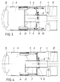
- FIG. 2 in which the elements corresponding to those of Figure 1 are indicated with like reference numbers, has a structure 9′ having such openings as to allow the cylinders 5 to operate between the support 6 of the head and the shield 2.
- the cylinders 5 determine the advancement of the shield 1 with respect to the shield 3 and, by varying the oil throughput, also the variations of the direction of advancement of the axially rigid structure comprised of the shield 1 and of the shield 3, axially rigid through the guides (7 and 8), guide 8 being fitted with suitable means to prevent shield 3′ from being dragged forward by friction.
- the telescopic overlap zone between the shield 1 and the shield 3 is realized at a greater distance with respect to the coupling zone between the shield 2 and the shield 3.
- the guides that control the relative motions of the shields 1 and 3 are made up of a tubular structure 7, substantially like that shown with reference to figures 1 and 2, that slides within the guide 8′, integral with the structure 9, that extends longitudinally about the tubular structure 7 to a lesser extent than the guide 8 of the preceding embodiments.
- a side structure is provided, between the shield 1 and the shield 3, comprised of side beams 13, sliding within side guides 14, that, together with the guide 8′, obliges the shields 1 and 3 to coaxially slide and supports the relevant stresses.
- the advancing cylinders 5 are provided, as well as the steering cylinders 10 and the torque cylinders 11.
- the cylinders 5 realize both the advancement of the shield 1, and the variation of the direction of the structure shield 1/ shield 3 with respect to the shield 2, as they are arranged between the support 6 of the head 15 and the shield 2 itself.
Landscapes
- Engineering & Computer Science (AREA)
- Mining & Mineral Resources (AREA)
- Environmental & Geological Engineering (AREA)
- Life Sciences & Earth Sciences (AREA)
- General Life Sciences & Earth Sciences (AREA)
- Geochemistry & Mineralogy (AREA)
- Geology (AREA)
- Excavating Of Shafts Or Tunnels (AREA)
- Earth Drilling (AREA)
- Knives (AREA)
- Removal Of Insulation Or Armoring From Wires Or Cables (AREA)
Claims (13)
- Bohrmaschine zum Bohren von Tunneln, sogenannte Doppelschildbohrmaschine, mit einem ersten, den Bohrkopf (15) und dessen Antriebsmittel enthaltenden Schild (1), einem zweiten mit "Greifer" versehenen Schild (2), die fuer die zum Vorruecken der Bohrmaschine notwendige Befestigung sorgen, und einem dritten, zwischen dem ersten und zweiten Schild angeordneten Schild (3), dadurch gekennzeichnet, dass der erste Schild den dritten Schild (3) uebergreift und gegenueber diesem dritten Schild (3) achsial gleitbar ist, und dass die durch den ersten (1) und dritten Schild (3) gebildete Anordnung ihre Bewegungsrichtung gegenueber dem zweiten Schild (2) aendem kann, wobei zwischen dem ersten Schild (1) und dem dritten Schild (3) Fuehrungsmittel vorgesehen sind, die eine relative konzentrische Bewegung dieses letzten nur in achsialen Laengsrichtung gestatten und dessen Verdrehung um die Laengsachse verhindern, wobei Mittel (5) zum Vorruecken des ersten Schilds (1) gegenueber dem dritten Schild (3) und Mittel (10) zum Verstellen der aus dem ersten (1) und dritten Schild (3) bestehenden Anordnung um einen Winkel gegenueber dem zweiten Schild (2) vorgesehen sind und wobei die vorgenannten Fuehrungsmittel zwischen dem ersten (1) und dem dritten Schild (3) aus einem, mit dem ersten Schild (1) einstueckigen und sich laengs der Achse erstreckenden Zentralgeruest (7) besteht, die in einer, auf dem dritten Svhild (3) angeordneten Fuehrung (8) gleitbar ist.
- Bohrmaschine nach Anspruch 1, worin das vorgenannte Zentralgeruest (7) ein rohrfoermiges Geruest ist.
- Bohrmaschine nach Anspruch 1 oder 2, dadurch gekennzeichnet, dass die Kupplung zwischen dem Zentralgeruest (7) und der Fuehrung (8) sich laengstlich erstreckt.
- Bohrmaschine nach Anspruch 1 oder 2, dadurch gekennzeichnet, dass die Kupplung zwischen dem Zentralgeruest (7) und der Fuehrung (8) sich laengstlich erstreckt, wobei zwischen dem ersten (1) und dem dritten Schild (3) weitere Fuehrungsmittel (13) vorgesehen sind.
- Bohrmaschine nach Anspruch 4, worin die vorgenannten weiteren Fuehrungsmittel (13) aus durch den vorgenannten ersten Schild getragenen Balken und entsprechenden, durch den dritten Schild (3) getragenen Umfangsfuehrungen bestehen.
- Bohrmaschine nach je einem der vorhergenden Ansprueche, dadurch gekennzeichnet, dass die teilweise Ueberlagerung zwischen dem ersten (1) und dem dritten Schild (3) in der Naehe des Kupplungsbereiches zwischen dem zweiten (2) und dem dritten Schild (3) vorgesehen ist.
- Bohrmaschine nach Anspruechen 1 bis 5 dadurch gekennzeichnet, dass die teilweise Ueberlagerung zwischen dem ersten (1) und dem dritten Schild (3) in einem gegenueber der Kupplung zwischen dem zweiten (2) und dem dritten Schild (3) entgegensetzen Bereich vorgesehen ist.
- Bohrmaschine nach je einem der vorhergehenden Anspruechen, dadurch gekennzeichnet, dass der vorgenannte erste Schild (1) am Ueberlagerungs-Bereich mit dem dritten Schild (3), vollkommen ausserhalb des dritten Schilds (3) selbst angeordnet ist.
- Bohrmaschine nach je einem der vorhergehenden Ansprueche, dadurch gekennzeichnet, dass die Mittel (5) zum Vorruecken des ersten Schilds (1) gegenueber dem dritten Schild (3) aus ersten, untereinander identischen, hydraulischen Zylindern (5) bestehen, die zwischen dem ersten und dem dritten Schild angeordnet und parallel gespeist sind und die die Mittel (10) zur winkelmaessigen Versetzung der auf dem ersten (1) und dritten Schild (3) bestehenden Anordnung gegenueber dem zweiten Schild (2) aus zweiten hydraulischen Zylindern (10) mit verstellbar Flussmenge bestehen, die zwischen dem zweiten (2) und dem dritten Schild (3) angeordnet sind.
- Bohrmaschine nach je einem der Ansprueche 1 bis 7, dadurch gekennzeichnet, dass die Mittel (5) zum Vorruecken des ersten Schildes gegenueber dem dritten Schild (3) und die Mittel (10) zum winkelmaessigen Versetzen der aus dem ersten (1) und dritten (Schild) bestehenden Anordnung gegenueber dem zweiten Schild (2) aus hydraulischen, untereinander identischen Zylindern mit verstellbar Flussmenge bestehen, die zwischen dem ersten (1) und dem zweiten Schild (2) angeordnet sind.
- Bohrmaschine nach je einem der vorhergehenden Ansprueche, dadurch gekennzeichnet, dass dritte hydraulische, untereinander identische Zylinder (11), die tangential in der zur Laengsachse der Schilder (1,2,3) senkrechten Ebene liegen und die Drehung der aus dem ersten (1) und dritten Schild (3) bestehenden Anordnung gegenueber dem zweiten Schild (2) steuern, zwischen dem zweiten (2) und dem dritten Schild (3) angeordnet sind.
- Bohrmaschine nach je einem der vorhergehenden Ansprueche, dadurch gekennzeichnet, dass der aeussere Teil des ersten Schildes (1) und/oder der aeussere Teil des dritten Schilder (3) aus abtrennbaren Abschmitten bestehen.
- Bohrmaschine nach je einem der vorhergehenden Ansprueche, dadurch gekennzeichnet, dass im teleskopischen Bereich Dichtungs- und Reinigungsmittel vorgesehen sind.
Applications Claiming Priority (2)
| Application Number | Priority Date | Filing Date | Title |
|---|---|---|---|
| IT47823A IT1241160B (it) | 1990-04-02 | 1990-04-02 | Fresa a doppio scudo telescopico perfezionata. |
| IT4782390 | 1990-04-02 |
Publications (2)
| Publication Number | Publication Date |
|---|---|
| EP0451116A1 EP0451116A1 (de) | 1991-10-09 |
| EP0451116B1 true EP0451116B1 (de) | 1994-10-19 |
Family
ID=11262741
Family Applications (1)
| Application Number | Title | Priority Date | Filing Date |
|---|---|---|---|
| EP91830113A Expired - Lifetime EP0451116B1 (de) | 1990-04-02 | 1991-03-25 | Verbesserte Teleskopdoppelschieldbohrmaschine |
Country Status (7)
| Country | Link |
|---|---|
| US (1) | US5174683A (de) |
| EP (1) | EP0451116B1 (de) |
| JP (1) | JPH06341288A (de) |
| AT (1) | ATE113116T1 (de) |
| CA (1) | CA2039261A1 (de) |
| DE (1) | DE69104640D1 (de) |
| IT (1) | IT1241160B (de) |
Families Citing this family (18)
| Publication number | Priority date | Publication date | Assignee | Title |
|---|---|---|---|---|
| US5836089A (en) * | 1993-02-22 | 1998-11-17 | Lipsker; Yitshaq | Excavating equipment fitted with surface clamps |
| IL104820A (en) * | 1993-02-22 | 1995-11-27 | Lipsker Yitschaq | Excavating machinery |
| JP2657788B2 (ja) * | 1995-05-12 | 1997-09-24 | 川崎重工業株式会社 | トンネル掘削機 |
| DE19722000A1 (de) | 1997-05-27 | 1998-12-03 | Wirth Co Kg Masch Bohr | Tunnelbohrmaschine |
| US6554368B2 (en) * | 2000-03-13 | 2003-04-29 | Oil Sands Underground Mining, Inc. | Method and system for mining hydrocarbon-containing materials |
| CA2470913C (en) * | 2002-01-09 | 2012-06-05 | Oil Sands Underground Mining, Inc. | Method and means for processing oil sands while excavating |
| US7128375B2 (en) * | 2003-06-04 | 2006-10-31 | Oil Stands Underground Mining Corp. | Method and means for recovering hydrocarbons from oil sands by underground mining |
| US8287050B2 (en) | 2005-07-18 | 2012-10-16 | Osum Oil Sands Corp. | Method of increasing reservoir permeability |
| CA2649850A1 (en) | 2006-04-21 | 2007-11-01 | Osum Oil Sands Corp. | Method of drilling from a shaft for underground recovery of hydrocarbons |
| CA2666506A1 (en) | 2006-10-16 | 2008-04-24 | Osum Oil Sands Corp. | Method of collecting hydrocarbons using a barrier tunnel |
| CA2668774A1 (en) | 2006-11-22 | 2008-05-29 | Osum Oil Sands Corp. | Recovery of bitumen by hydraulic excavation |
| US8167960B2 (en) | 2007-10-22 | 2012-05-01 | Osum Oil Sands Corp. | Method of removing carbon dioxide emissions from in-situ recovery of bitumen and heavy oil |
| US8176982B2 (en) | 2008-02-06 | 2012-05-15 | Osum Oil Sands Corp. | Method of controlling a recovery and upgrading operation in a reservoir |
| US8209192B2 (en) | 2008-05-20 | 2012-06-26 | Osum Oil Sands Corp. | Method of managing carbon reduction for hydrocarbon producers |
| US7832960B2 (en) * | 2008-12-17 | 2010-11-16 | The Robbins Company | All-conditions tunnel boring machine |
| CN103575529B (zh) * | 2013-11-21 | 2015-11-18 | 中国建筑股份有限公司 | 一种盾构管片试验机加载系统及盾构管片试验机 |
| CN104389611A (zh) * | 2014-11-12 | 2015-03-04 | 中国铁建重工集团有限公司 | 掘进机及其隧道管片调整装置 |
| CN114075982A (zh) * | 2021-11-25 | 2022-02-22 | 济南重工集团有限公司 | 一种超大直径盾构机主驱动调心和防扭装置 |
Family Cites Families (6)
| Publication number | Priority date | Publication date | Assignee | Title |
|---|---|---|---|---|
| DE384612C (de) * | 1922-01-20 | 1923-11-05 | Maerkische Schlossindustrie G | Fallenschloss |
| US3350889A (en) * | 1964-04-15 | 1967-11-07 | Sturm Karl | Apparatus for driving and lining tunnels in unstable soil |
| DE2615264C2 (de) * | 1976-04-08 | 1985-01-03 | Gewerkschaft Eisenhütte Westfalia, 4670 Lünen | Richtungssteuerungseinrichtung für eine Vortriebseinrichtung für das Auffahren von Tunneln, Stollen u.dgl. |
| GB2024891B (en) * | 1978-07-05 | 1982-06-30 | Goldsby E F | Tunnellingshield |
| DE2852663C2 (de) * | 1978-12-06 | 1986-04-17 | Gewerkschaft Eisenhütte Westfalia, 4670 Lünen | Messerschild |
| FR2528108A1 (fr) * | 1982-06-02 | 1983-12-09 | Bessac Michel | Machine perfectionnee a bouclier pour le creusement de galeries souterraines |
-
1990
- 1990-04-02 IT IT47823A patent/IT1241160B/it active IP Right Grant
-
1991
- 1991-03-22 US US07/673,638 patent/US5174683A/en not_active Expired - Fee Related
- 1991-03-25 AT AT91830113T patent/ATE113116T1/de not_active IP Right Cessation
- 1991-03-25 EP EP91830113A patent/EP0451116B1/de not_active Expired - Lifetime
- 1991-03-25 DE DE69104640T patent/DE69104640D1/de not_active Expired - Lifetime
- 1991-03-27 CA CA002039261A patent/CA2039261A1/en not_active Abandoned
- 1991-04-02 JP JP3069999A patent/JPH06341288A/ja active Pending
Also Published As
| Publication number | Publication date |
|---|---|
| IT9047823A1 (it) | 1991-10-02 |
| CA2039261A1 (en) | 1991-10-03 |
| JPH06341288A (ja) | 1994-12-13 |
| US5174683A (en) | 1992-12-29 |
| IT1241160B (it) | 1993-12-29 |
| IT9047823A0 (it) | 1990-04-02 |
| DE69104640D1 (de) | 1994-11-24 |
| ATE113116T1 (de) | 1994-11-15 |
| EP0451116A1 (de) | 1991-10-09 |
Similar Documents
| Publication | Publication Date | Title |
|---|---|---|
| EP0451116B1 (de) | Verbesserte Teleskopdoppelschieldbohrmaschine | |
| US4212497A (en) | Liquid discharge apparatus for a shearing-loader type mining machine | |
| US4548443A (en) | Tunnel boring machine | |
| CN110985020B (zh) | 一种具备刀盘独立伸缩和摆动超挖能力的主动铰接盾构机 | |
| EP0268188B1 (de) | Tunnelvortriebsschild | |
| CN112554899B (zh) | 一种硬岩隧道掘进机 | |
| US4251112A (en) | Apparatus for pivotally positioning a clearing shield for a drum-cutter mining machine | |
| US5135326A (en) | Articulated shield tunneling machine | |
| CA2169048A1 (en) | Open cast mining apparatus | |
| CN115288710B (zh) | 一种可采用中心螺机出渣的掘进机 | |
| CN117365516A (zh) | 全断面掘进机及其出渣系统、螺旋输送机 | |
| JP5017633B2 (ja) | シールドマシン | |
| EP4158155A1 (de) | Trommelschneideranordnung | |
| JP7699419B2 (ja) | シールド掘進機 | |
| JP7693262B2 (ja) | シールド掘進機 | |
| JP7693263B2 (ja) | シールド掘進機 | |
| JP7693261B2 (ja) | シールド掘進機 | |
| US4438821A (en) | Mining machinery | |
| JP3414094B2 (ja) | セグメント組立装置 | |
| US3695725A (en) | Mining machine drum cutter | |
| US12173607B2 (en) | Tunnel excavation device | |
| CA3085203C (en) | Center pintle hub | |
| JP4020498B2 (ja) | 偏芯多軸掘削機 | |
| JP3154476B2 (ja) | 鋼管分割体セグメント | |
| JP3958439B2 (ja) | 偏芯多軸掘削機 |
Legal Events
| Date | Code | Title | Description |
|---|---|---|---|
| PUAI | Public reference made under article 153(3) epc to a published international application that has entered the european phase |
Free format text: ORIGINAL CODE: 0009012 |
|
| AK | Designated contracting states |
Kind code of ref document: A1 Designated state(s): AT BE CH DE DK ES FR GB GR LI LU NL SE |
|
| RBV | Designated contracting states (corrected) |
Designated state(s): AT DE FR GB |
|
| 17P | Request for examination filed |
Effective date: 19920310 |
|
| 17Q | First examination report despatched |
Effective date: 19930526 |
|
| GRAA | (expected) grant |
Free format text: ORIGINAL CODE: 0009210 |
|
| AK | Designated contracting states |
Kind code of ref document: B1 Designated state(s): AT DE FR GB |
|
| PG25 | Lapsed in a contracting state [announced via postgrant information from national office to epo] |
Ref country code: FR Effective date: 19941019 Ref country code: AT Effective date: 19941019 |
|
| REF | Corresponds to: |
Ref document number: 113116 Country of ref document: AT Date of ref document: 19941115 Kind code of ref document: T |
|
| REF | Corresponds to: |
Ref document number: 69104640 Country of ref document: DE Date of ref document: 19941124 |
|
| PG25 | Lapsed in a contracting state [announced via postgrant information from national office to epo] |
Ref country code: DE Effective date: 19950120 |
|
| EN | Fr: translation not filed | ||
| PG25 | Lapsed in a contracting state [announced via postgrant information from national office to epo] |
Ref country code: GB Effective date: 19950325 |
|
| PLBE | No opposition filed within time limit |
Free format text: ORIGINAL CODE: 0009261 |
|
| STAA | Information on the status of an ep patent application or granted ep patent |
Free format text: STATUS: NO OPPOSITION FILED WITHIN TIME LIMIT |
|
| 26N | No opposition filed | ||
| GBPC | Gb: european patent ceased through non-payment of renewal fee |
Effective date: 19950325 |