EP0451316A1 - Procédé de montage d'un système de rail conducteur et connecteur associé - Google Patents
Procédé de montage d'un système de rail conducteur et connecteur associé Download PDFInfo
- Publication number
- EP0451316A1 EP0451316A1 EP90107144A EP90107144A EP0451316A1 EP 0451316 A1 EP0451316 A1 EP 0451316A1 EP 90107144 A EP90107144 A EP 90107144A EP 90107144 A EP90107144 A EP 90107144A EP 0451316 A1 EP0451316 A1 EP 0451316A1
- Authority
- EP
- European Patent Office
- Prior art keywords
- rails
- busbars
- connector
- mounting
- rail
- Prior art date
- Legal status (The legal status is an assumption and is not a legal conclusion. Google has not performed a legal analysis and makes no representation as to the accuracy of the status listed.)
- Granted
Links
- 238000000034 method Methods 0.000 title claims abstract description 7
- 239000002184 metal Substances 0.000 claims description 34
- 239000004020 conductor Substances 0.000 claims description 10
- 229910000906 Bronze Inorganic materials 0.000 claims description 3
- 230000015572 biosynthetic process Effects 0.000 claims description 3
- 239000010974 bronze Substances 0.000 claims description 3
- KUNSUQLRTQLHQQ-UHFFFAOYSA-N copper tin Chemical compound [Cu].[Sn] KUNSUQLRTQLHQQ-UHFFFAOYSA-N 0.000 claims description 3
- 238000005755 formation reaction Methods 0.000 claims description 3
- 238000009434 installation Methods 0.000 description 3
- 210000001503 joint Anatomy 0.000 description 2
- 238000004519 manufacturing process Methods 0.000 description 2
- 230000000052 comparative effect Effects 0.000 description 1
- 238000010276 construction Methods 0.000 description 1
- 238000005260 corrosion Methods 0.000 description 1
- 230000007797 corrosion Effects 0.000 description 1
- 239000000463 material Substances 0.000 description 1
- 238000004904 shortening Methods 0.000 description 1
Images


Classifications
-
- B—PERFORMING OPERATIONS; TRANSPORTING
- B60—VEHICLES IN GENERAL
- B60M—POWER SUPPLY LINES, AND DEVICES ALONG RAILS, FOR ELECTRICALLY- PROPELLED VEHICLES
- B60M1/00—Power supply lines for contact with collector on vehicle
- B60M1/30—Power rails
- B60M1/34—Power rails in slotted conduits
Definitions
- the invention relates, on the one hand, to a method for assembling a rail system comprising mounting rails and a conductor rail system fastened thereon, which for each mounting rail comprises at least two parallel busbars, each releasing a grinding surface on one side, the mounting rails being laid in abutment and the busbars being joined by the grinding surface facing away from the mounting rail are fastened to the respective mounting rail with the aid of base clamps and then the mutually assigned ends of the busbars are connected to one another with a connector, and on the other hand a connector suitable for this method.
- the mentioned rail system can be, for example, a monorail conveyor.
- the mounting rails can consequently also serve as rails.
- the connector for connecting the associated ends of the busbars consists of four parts, namely two plugs, a metal sleeve which can be plugged onto them and an insulating cover part.
- a plug is inserted into the two assigned ends of the busbars, the metal sleeve being pushed onto the free ends protruding from the busbars; this is only possible if the mutually assigned ends of the busbars in the longitudinal direction are not yet permanently attached to the mounting rail.
- the cover must then be pushed onto the metal sleeve from behind through the space between the cover sleeve and the mounting rail. After that, the final fixation on the mounting rails is only possible. All of this is relatively complex and cumbersome. Only specialists can be used for on-site assembly.
- the invention has for its object to prefabricate the rail system factory so far that only work needs to be carried out at the installation site that can be easily carried out by assistants.
- the present invention teaches from a procedural point of view that the conductor rails are fixed to the carrier rails with ends shortened relative to the respective carrier rail with central longitudinal fixation prior to the laying of the carrier rails, and after the carrier rails provided with the conductor rails are laid, the connectors are connected exclusively by perpendicular to the grinding surface, to be placed on the ends of the conductor rails towards the mounting rail.
- a particularly suitable for this method connector is characterized in that it consists only of a clamping bracket with mutually parallel, the associated busbar covering and provided with clamping formations clamping legs and this approximately centrally connecting grinding surface web, the clamping legs being seen in the longitudinal direction of the mounting rails longer and the Grinding surface web are shorter than the distance between the assigned ends of the busbars.
- the conductor rail system is factory-attached to the mounting rails except for the connectors.
- the assembly on site is carried out as with the previous mounting rail installation, d. H. no technical considerations need to be taken of the power rails.
- the connector can be designed as a line connector for busbars made of metal rails and an insulating jacket removed at the ends of the metal rails; in fact, the removal of the insulating jacket from the ends of the metal rails is much easier in the factory than on site.
- a connector is preferably characterized by a metal bracket fastened in an insulating housing, the insulating housing being longer and the metal bracket being shorter than the distance between the associated ends of the insulating jacket when viewed in the longitudinal direction of the mounting rails; the metal bracket then creates the conductive connection between the stripped metal rail ends, while the insulating housing covers the whole thing down to the grinding surface, so that protection against contact is guaranteed.
- the metal bracket is expediently made of spring bronze. In the contact area of its clamping legs, this metal bracket should have raised contact points, with the help of which during the train corrosion layers formed during the working of the connection are, as it were, scraped off automatically. It is also possible to provide the metal bracket with a connecting line or feed line. Since the insulating housing cannot be handled separately from the metal bracket, the metal bracket according to a preferred embodiment has mounting recesses for the insulating housing. The latter can have a shortened housing bridge behind the grinding surface web; this housing bridge stiffens the connector further, the shortening ensuring that the connector can also be inserted between the associated ends of the busbars.
- the connector can also be easily designed as an insulating connector; for this purpose it is advisable to manufacture the connector entirely from an insulating plastic material. In all cases it is advisable to provide the connector with longitudinal stops for the ends of the insulating jacket. Longitudinal stops for the metal rails of the conductor rails are not necessary because these stops are automatically formed by the grinding surface web.
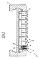
- the rail system shown in Figures 1 to 3 consists in its basic structure of mounting rails 1 and a conductor rail system 2 attached to it.
- This conductor rail system 2 comprises for each mounting rail 1 nine mutually parallel busbars 3, each of which releases a recessed grinding surface 4 on the same side.
- the mounting rails 1 are laid in a butt joint.
- the busbars 3 are fastened to the respective mounting rail 1 with the grinding surface 4 facing away from the mounting rail 1 with the aid of support terminals 5.
- the mutually associated ends 6 of the busbars 3 are each connected to one another by a connector 7.
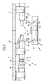
- the busbars 3 are before laying the mounting rails 1 with shortened ends 6 relative to the respective mounting rail 1, with central longitudinal fixation (at 8) attached to the mounting rails. Thereafter, the connector 7 is then clamped onto the ends 6 of the busbars 3 exclusively by being placed perpendicular to the grinding surface 4 and towards the mounting rail.
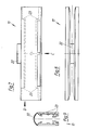
- the construction of the connector 7 results in particular from FIGS. 4 to 9. It consists of a clamping bracket 9 with mutually parallel clamping legs 12, which encompass the associated busbars 3 and are provided with clamping designs 10, 11, and the grinding surface web 13 connecting them approximately centrally Seen support rails 1, the clamping legs 12 are longer than the distance between the associated ends 6 of the busbars 3, while the grinding surface web 13 is shorter than the aforementioned distance.
- the clamping formations 10, 11 consist of front retaining arches 10, which form a stop when pushed on, and of a rear clamping fold 11, which, as it were, falls behind the busbar 3.
- the embodiment is always shown as a line connector for busbars 3 made of metal rail 14 and insulating jacket 15 removed at the ends of the metal rails 14.
- the connector is designed here as a metal bracket 16 which is fastened in an insulating housing 17, the insulating housing being seen in the longitudinal direction of the mounting rails 1 17 longer and the metal bracket 16 is shorter than the distance between the associated ends 18 of the insulating jacket 15.
- the metal bracket 16 is shown in Figures 4 to 6 in detail, while the details of the insulating housing 17 can be seen from Figures 7 to 9.
- the metal bracket 16 made of spring bronze has raised contact points 19 in the contact area of its clamping legs 12.
- Fig. 2 it is indicated schematically that the metal bracket 16 can also be provided with a connecting line 20.
- the metal bracket 16 has mounting recesses 21 for the insulating housing 17.
- the insulating housing 17 has a housing bridge 22 that is shortened behind the grinding surface web 13.
- the busbars 3 are fastened to the mounting rails 1 at the production site and then brought to the installation site. There, the mounting rails 1 are laid without regard to the busbars 3. Then only the connectors 7 are attached, as can be seen from a comparative view of FIGS. 2 and 3.
Landscapes
- Engineering & Computer Science (AREA)
- Mechanical Engineering (AREA)
- Connector Housings Or Holding Contact Members (AREA)
- Manufacturing Of Electrical Connectors (AREA)
- Coupling Device And Connection With Printed Circuit (AREA)
- Electric Propulsion And Braking For Vehicles (AREA)
- Machines For Laying And Maintaining Railways (AREA)
- Magnetic Heads (AREA)
- Automobile Manufacture Line, Endless Track Vehicle, Trailer (AREA)
- Multi-Conductor Connections (AREA)
Priority Applications (6)
| Application Number | Priority Date | Filing Date | Title |
|---|---|---|---|
| ES90107144T ES2026829T3 (es) | 1990-04-13 | 1990-04-13 | Procedimiento para montar un sistema para ferrocarriles y conector idoneo para ello. |
| EP90107144A EP0451316B1 (fr) | 1990-04-13 | 1990-04-13 | Procédé de montage d'un système de rail conducteur et connecteur associé |
| AT90107144T ATE97618T1 (de) | 1990-04-13 | 1990-04-13 | Verfahren zum montieren eines bahnsystems und hierfuer geeigneter verbinder. |
| DK90107144.9T DK0451316T3 (da) | 1990-04-13 | 1990-04-13 | Fremgangsmåde til montering af et banesystem, og forbindelsesorgan til brug ved denne |
| DE90107144T DE59003629D1 (de) | 1990-04-13 | 1990-04-13 | Verfahren zum Montieren eines Bahnsystems und hierfür geeigneter Verbinder. |
| GR91300142T GR910300142T1 (en) | 1990-04-13 | 1992-06-30 | Mounting process for a conductive railsystem and associated connector |
Applications Claiming Priority (1)
| Application Number | Priority Date | Filing Date | Title |
|---|---|---|---|
| EP90107144A EP0451316B1 (fr) | 1990-04-13 | 1990-04-13 | Procédé de montage d'un système de rail conducteur et connecteur associé |
Publications (2)
| Publication Number | Publication Date |
|---|---|
| EP0451316A1 true EP0451316A1 (fr) | 1991-10-16 |
| EP0451316B1 EP0451316B1 (fr) | 1993-11-24 |
Family
ID=8203884
Family Applications (1)
| Application Number | Title | Priority Date | Filing Date |
|---|---|---|---|
| EP90107144A Expired - Lifetime EP0451316B1 (fr) | 1990-04-13 | 1990-04-13 | Procédé de montage d'un système de rail conducteur et connecteur associé |
Country Status (6)
| Country | Link |
|---|---|
| EP (1) | EP0451316B1 (fr) |
| AT (1) | ATE97618T1 (fr) |
| DE (1) | DE59003629D1 (fr) |
| DK (1) | DK0451316T3 (fr) |
| ES (1) | ES2026829T3 (fr) |
| GR (1) | GR910300142T1 (fr) |
Cited By (2)
| Publication number | Priority date | Publication date | Assignee | Title |
|---|---|---|---|---|
| WO2007054200A1 (fr) * | 2005-11-08 | 2007-05-18 | Sew-Eurodrive Gmbh & Co. Kg | Systeme pour maintenir des cables |
| DE10227079B4 (de) * | 2001-06-18 | 2010-06-02 | Akapp Electro Industrie B.V. | Stromschienesystem |
Citations (2)
| Publication number | Priority date | Publication date | Assignee | Title |
|---|---|---|---|---|
| GB2137439A (en) * | 1983-03-31 | 1984-10-03 | Mannesmann Ag | Conductor rail joint |
| EP0197811A1 (fr) * | 1985-03-11 | 1986-10-15 | Delachaux S.A. | Dispositif de raccordement électrique pour élément de barre conductrice à joint de dilatation |
-
1990
- 1990-04-13 DK DK90107144.9T patent/DK0451316T3/da active
- 1990-04-13 AT AT90107144T patent/ATE97618T1/de not_active IP Right Cessation
- 1990-04-13 DE DE90107144T patent/DE59003629D1/de not_active Expired - Fee Related
- 1990-04-13 EP EP90107144A patent/EP0451316B1/fr not_active Expired - Lifetime
- 1990-04-13 ES ES90107144T patent/ES2026829T3/es not_active Expired - Lifetime
-
1992
- 1992-06-30 GR GR91300142T patent/GR910300142T1/el unknown
Patent Citations (2)
| Publication number | Priority date | Publication date | Assignee | Title |
|---|---|---|---|---|
| GB2137439A (en) * | 1983-03-31 | 1984-10-03 | Mannesmann Ag | Conductor rail joint |
| EP0197811A1 (fr) * | 1985-03-11 | 1986-10-15 | Delachaux S.A. | Dispositif de raccordement électrique pour élément de barre conductrice à joint de dilatation |
Cited By (3)
| Publication number | Priority date | Publication date | Assignee | Title |
|---|---|---|---|---|
| DE10227079B4 (de) * | 2001-06-18 | 2010-06-02 | Akapp Electro Industrie B.V. | Stromschienesystem |
| WO2007054200A1 (fr) * | 2005-11-08 | 2007-05-18 | Sew-Eurodrive Gmbh & Co. Kg | Systeme pour maintenir des cables |
| CN101304896B (zh) * | 2005-11-08 | 2010-09-08 | 索尤若驱动有限及两合公司 | 用于保持电缆的系统 |
Also Published As
| Publication number | Publication date |
|---|---|
| ES2026829T1 (es) | 1992-05-16 |
| ATE97618T1 (de) | 1993-12-15 |
| ES2026829T3 (es) | 1994-03-01 |
| GR910300142T1 (en) | 1992-06-30 |
| DK0451316T3 (da) | 1993-12-27 |
| EP0451316B1 (fr) | 1993-11-24 |
| DE59003629D1 (de) | 1994-01-05 |
Similar Documents
| Publication | Publication Date | Title |
|---|---|---|
| DE1590197A1 (de) | Flaechig ausgebildeter isolierter Anschlussteil | |
| DE3740290C2 (de) | Vorrichtung zum Steuern und/oder Regeln von Prozessen | |
| EP1475565B1 (fr) | Ensemble d'éclairage | |
| DE69711369T2 (de) | Modularer Kammverbinder für Schnittstellenrelais | |
| DE102017128756A1 (de) | Kurzstab, Kurzstabeinheit und Motorfahrvorrichtung | |
| DE4310369A1 (de) | Adapter | |
| EP0451316B1 (fr) | Procédé de montage d'un système de rail conducteur et connecteur associé | |
| EP0681343B1 (fr) | Système pour le raccordement à la masse de câbles électriques, en particulier à une carrosserie automobile | |
| EP3540304B1 (fr) | Système de réalisation d'une bande lumineuse | |
| DE2315062A1 (de) | Vielfachsteckanschlusstueck | |
| DE2743033A1 (de) | Vorrichtung zum verhindern falscher elektrischer steckverbindungen | |
| EP0148334B1 (fr) | Dispositif pour la fixation d'accessoires sur la paroi d'une armature lumineuse | |
| DE19819056C1 (de) | Steckverbinder für elektrische Flachleitungen | |
| DE3521910A1 (de) | Beleuchtungssystem | |
| DE2723725C3 (de) | Elektrische Mehrfachkupplung | |
| DE2119572B2 (de) | Stromverteilungssystem | |
| DE69500510T2 (de) | Elektrischer Stromkreis aus abgeschnittenen Streifen, insbesondere für einen Zusammenbau von Warnleuchten eines Kraftfahrzeugs welcher verbesserte männliche Verbindungselemente aufweist | |
| DE69404490T2 (de) | Beleuchtungskörper für Leuchtröhre und dazu bestimmtes Zubehör | |
| DE29823911U1 (de) | Auf einer Sammelschiene befestigte, elektrisch miteinander verbundene Stromabnehmer | |
| EP0264598A2 (fr) | Module de centrage pour le guidage et la réception d'une fiche de câble pouvant être blindée | |
| EP0339492B1 (fr) | Dispositif pour connecter facultativement des lignes électriques | |
| DE2547587C2 (de) | Vielfachsteckvorrichtung | |
| DE102006022987B3 (de) | Verbindungselement | |
| DE1137784B (de) | Kontaktanordnung fuer elektrische Steckverbindungen | |
| DE2619032C3 (de) | Einphasiger Trennsteckverteiler für Energieversorgungsnetze im Mittelspannungsbereich |
Legal Events
| Date | Code | Title | Description |
|---|---|---|---|
| PUAI | Public reference made under article 153(3) epc to a published international application that has entered the european phase |
Free format text: ORIGINAL CODE: 0009012 |
|
| 17P | Request for examination filed |
Effective date: 19910124 |
|
| AK | Designated contracting states |
Kind code of ref document: A1 Designated state(s): AT BE CH DE DK ES FR GB GR IT LI LU NL SE |
|
| TCNL | Nl: translation of patent claims filed | ||
| GBC | Gb: translation of claims filed (gb section 78(7)/1977) | ||
| EL | Fr: translation of claims filed | ||
| 17Q | First examination report despatched |
Effective date: 19930511 |
|
| GRAA | (expected) grant |
Free format text: ORIGINAL CODE: 0009210 |
|
| AK | Designated contracting states |
Kind code of ref document: B1 Designated state(s): AT BE CH DE DK ES FR GB GR IT LI LU NL SE |
|
| REF | Corresponds to: |
Ref document number: 97618 Country of ref document: AT Date of ref document: 19931215 Kind code of ref document: T |
|
| REG | Reference to a national code |
Ref country code: DK Ref legal event code: T3 |
|
| REF | Corresponds to: |
Ref document number: 59003629 Country of ref document: DE Date of ref document: 19940105 |
|
| ET | Fr: translation filed | ||
| ITF | It: translation for a ep patent filed | ||
| GBT | Gb: translation of ep patent filed (gb section 77(6)(a)/1977) |
Effective date: 19940111 |
|
| REG | Reference to a national code |
Ref country code: GR Ref legal event code: FG4A Free format text: 3010187 |
|
| REG | Reference to a national code |
Ref country code: ES Ref legal event code: FG2A Ref document number: 2026829 Country of ref document: ES Kind code of ref document: T3 |
|
| EPTA | Lu: last paid annual fee | ||
| PLBE | No opposition filed within time limit |
Free format text: ORIGINAL CODE: 0009261 |
|
| STAA | Information on the status of an ep patent application or granted ep patent |
Free format text: STATUS: NO OPPOSITION FILED WITHIN TIME LIMIT |
|
| 26N | No opposition filed | ||
| EAL | Se: european patent in force in sweden |
Ref document number: 90107144.9 |
|
| PGFP | Annual fee paid to national office [announced via postgrant information from national office to epo] |
Ref country code: GR Payment date: 19950201 Year of fee payment: 6 |
|
| PGFP | Annual fee paid to national office [announced via postgrant information from national office to epo] |
Ref country code: LU Payment date: 19950301 Year of fee payment: 6 |
|
| PGFP | Annual fee paid to national office [announced via postgrant information from national office to epo] |
Ref country code: ES Payment date: 19950404 Year of fee payment: 6 |
|
| PGFP | Annual fee paid to national office [announced via postgrant information from national office to epo] |
Ref country code: DK Payment date: 19950419 Year of fee payment: 6 |
|
| PGFP | Annual fee paid to national office [announced via postgrant information from national office to epo] |
Ref country code: AT Payment date: 19950420 Year of fee payment: 6 |
|
| PGFP | Annual fee paid to national office [announced via postgrant information from national office to epo] |
Ref country code: CH Payment date: 19950421 Year of fee payment: 6 |
|
| PGFP | Annual fee paid to national office [announced via postgrant information from national office to epo] |
Ref country code: NL Payment date: 19950430 Year of fee payment: 6 |
|
| PGFP | Annual fee paid to national office [announced via postgrant information from national office to epo] |
Ref country code: SE Payment date: 19950502 Year of fee payment: 6 |
|
| PG25 | Lapsed in a contracting state [announced via postgrant information from national office to epo] |
Ref country code: DK Effective date: 19960413 Ref country code: LU Free format text: LAPSE BECAUSE OF NON-PAYMENT OF DUE FEES Effective date: 19960413 Ref country code: AT Effective date: 19960413 |
|
| REG | Reference to a national code |
Ref country code: DK Ref legal event code: EBP |
|
| PG25 | Lapsed in a contracting state [announced via postgrant information from national office to epo] |
Ref country code: SE Effective date: 19960414 |
|
| PG25 | Lapsed in a contracting state [announced via postgrant information from national office to epo] |
Ref country code: ES Free format text: LAPSE BECAUSE OF NON-PAYMENT OF DUE FEES Effective date: 19960415 |
|
| PG25 | Lapsed in a contracting state [announced via postgrant information from national office to epo] |
Ref country code: CH Effective date: 19960430 Ref country code: LI Effective date: 19960430 |
|
| PG25 | Lapsed in a contracting state [announced via postgrant information from national office to epo] |
Ref country code: GR Free format text: THE PATENT HAS BEEN ANNULLED BY A DECISION OF A NATIONAL AUTHORITY Effective date: 19961031 |
|
| PG25 | Lapsed in a contracting state [announced via postgrant information from national office to epo] |
Ref country code: NL Effective date: 19961101 |
|
| REG | Reference to a national code |
Ref country code: GR Ref legal event code: MM2A Free format text: 3010187 |
|
| REG | Reference to a national code |
Ref country code: CH Ref legal event code: PL |
|
| NLV4 | Nl: lapsed or anulled due to non-payment of the annual fee |
Effective date: 19961101 |
|
| EUG | Se: european patent has lapsed |
Ref document number: 90107144.9 |
|
| REG | Reference to a national code |
Ref country code: ES Ref legal event code: FD2A Effective date: 19990503 |
|
| REG | Reference to a national code |
Ref country code: GB Ref legal event code: IF02 |
|
| PGFP | Annual fee paid to national office [announced via postgrant information from national office to epo] |
Ref country code: DE Payment date: 20040212 Year of fee payment: 15 |
|
| PGFP | Annual fee paid to national office [announced via postgrant information from national office to epo] |
Ref country code: GB Payment date: 20050404 Year of fee payment: 16 |
|
| PGFP | Annual fee paid to national office [announced via postgrant information from national office to epo] |
Ref country code: FR Payment date: 20050412 Year of fee payment: 16 |
|
| PG25 | Lapsed in a contracting state [announced via postgrant information from national office to epo] |
Ref country code: IT Free format text: LAPSE BECAUSE OF NON-PAYMENT OF DUE FEES Effective date: 20050413 |
|
| PGFP | Annual fee paid to national office [announced via postgrant information from national office to epo] |
Ref country code: BE Payment date: 20050509 Year of fee payment: 16 |
|
| PG25 | Lapsed in a contracting state [announced via postgrant information from national office to epo] |
Ref country code: DE Free format text: LAPSE BECAUSE OF NON-PAYMENT OF DUE FEES Effective date: 20051101 |
|
| PG25 | Lapsed in a contracting state [announced via postgrant information from national office to epo] |
Ref country code: GB Free format text: LAPSE BECAUSE OF NON-PAYMENT OF DUE FEES Effective date: 20060413 |
|
| PG25 | Lapsed in a contracting state [announced via postgrant information from national office to epo] |
Ref country code: BE Free format text: LAPSE BECAUSE OF NON-PAYMENT OF DUE FEES Effective date: 20060430 |
|
| GBPC | Gb: european patent ceased through non-payment of renewal fee |
Effective date: 20060413 |
|
| REG | Reference to a national code |
Ref country code: FR Ref legal event code: ST Effective date: 20061230 |
|
| BERE | Be: lapsed |
Owner name: *FAHRLEITUNGSBAU G.M.B.H. Effective date: 20060430 |
|
| PG25 | Lapsed in a contracting state [announced via postgrant information from national office to epo] |
Ref country code: FR Free format text: LAPSE BECAUSE OF NON-PAYMENT OF DUE FEES Effective date: 20060502 |
|
| PGFP | Annual fee paid to national office [announced via postgrant information from national office to epo] |
Ref country code: IT Payment date: 20060430 Year of fee payment: 17 |
|
| PGRI | Patent reinstated in contracting state [announced from national office to epo] |
Ref country code: IT Effective date: 20080301 |
|
| PGRI | Patent reinstated in contracting state [announced from national office to epo] |
Ref country code: IT Effective date: 20080301 |