EP0451326A1 - Druckregulierventilvorrichtung - Google Patents
Druckregulierventilvorrichtung Download PDFInfo
- Publication number
- EP0451326A1 EP0451326A1 EP19900118645 EP90118645A EP0451326A1 EP 0451326 A1 EP0451326 A1 EP 0451326A1 EP 19900118645 EP19900118645 EP 19900118645 EP 90118645 A EP90118645 A EP 90118645A EP 0451326 A1 EP0451326 A1 EP 0451326A1
- Authority
- EP
- European Patent Office
- Prior art keywords
- diaphragm
- interior space
- recited
- pressure regulating
- fluid
- Prior art date
- Legal status (The legal status is an assumption and is not a legal conclusion. Google has not performed a legal analysis and makes no representation as to the accuracy of the status listed.)
- Withdrawn
Links
- 230000001105 regulatory effect Effects 0.000 title claims abstract description 68
- 239000012530 fluid Substances 0.000 claims abstract description 105
- 238000011144 upstream manufacturing Methods 0.000 claims abstract description 16
- 230000006835 compression Effects 0.000 claims description 18
- 238000007906 compression Methods 0.000 claims description 18
- 230000000717 retained effect Effects 0.000 claims description 8
- 238000004891 communication Methods 0.000 claims description 7
- 230000000670 limiting effect Effects 0.000 claims description 3
- 230000001276 controlling effect Effects 0.000 abstract description 4
- 239000011800 void material Substances 0.000 abstract 1
- 238000004140 cleaning Methods 0.000 description 6
- 238000010276 construction Methods 0.000 description 5
- 239000000463 material Substances 0.000 description 4
- 239000003814 drug Substances 0.000 description 3
- 230000002411 adverse Effects 0.000 description 2
- 235000013361 beverage Nutrition 0.000 description 2
- 229940079593 drug Drugs 0.000 description 2
- 230000000694 effects Effects 0.000 description 2
- 238000005498 polishing Methods 0.000 description 2
- 230000002829 reductive effect Effects 0.000 description 2
- 230000006978 adaptation Effects 0.000 description 1
- 239000000853 adhesive Substances 0.000 description 1
- 230000001070 adhesive effect Effects 0.000 description 1
- 244000052616 bacterial pathogen Species 0.000 description 1
- 230000009286 beneficial effect Effects 0.000 description 1
- 238000012790 confirmation Methods 0.000 description 1
- 230000003670 easy-to-clean Effects 0.000 description 1
- 239000007789 gas Substances 0.000 description 1
- 238000012423 maintenance Methods 0.000 description 1
- 238000012986 modification Methods 0.000 description 1
- 230000004048 modification Effects 0.000 description 1
- 238000004806 packaging method and process Methods 0.000 description 1
- 230000036961 partial effect Effects 0.000 description 1
- 239000012858 resilient material Substances 0.000 description 1
- 238000007711 solidification Methods 0.000 description 1
- 230000008023 solidification Effects 0.000 description 1
- 238000006467 substitution reaction Methods 0.000 description 1
- 230000003746 surface roughness Effects 0.000 description 1
- 238000003466 welding Methods 0.000 description 1
Images

Classifications
-
- G—PHYSICS
- G05—CONTROLLING; REGULATING
- G05D—SYSTEMS FOR CONTROLLING OR REGULATING NON-ELECTRIC VARIABLES
- G05D16/00—Control of fluid pressure
- G05D16/04—Control of fluid pressure without auxiliary power
- G05D16/06—Control of fluid pressure without auxiliary power the sensing element being a flexible membrane, yielding to pressure, e.g. diaphragm, bellows, capsule
- G05D16/063—Control of fluid pressure without auxiliary power the sensing element being a flexible membrane, yielding to pressure, e.g. diaphragm, bellows, capsule the sensing element being a membrane
- G05D16/0644—Control of fluid pressure without auxiliary power the sensing element being a flexible membrane, yielding to pressure, e.g. diaphragm, bellows, capsule the sensing element being a membrane the membrane acting directly on the obturator
- G05D16/0655—Control of fluid pressure without auxiliary power the sensing element being a flexible membrane, yielding to pressure, e.g. diaphragm, bellows, capsule the sensing element being a membrane the membrane acting directly on the obturator using one spring-loaded membrane
-
- Y—GENERAL TAGGING OF NEW TECHNOLOGICAL DEVELOPMENTS; GENERAL TAGGING OF CROSS-SECTIONAL TECHNOLOGIES SPANNING OVER SEVERAL SECTIONS OF THE IPC; TECHNICAL SUBJECTS COVERED BY FORMER USPC CROSS-REFERENCE ART COLLECTIONS [XRACs] AND DIGESTS
- Y10—TECHNICAL SUBJECTS COVERED BY FORMER USPC
- Y10T—TECHNICAL SUBJECTS COVERED BY FORMER US CLASSIFICATION
- Y10T137/00—Fluid handling
- Y10T137/7722—Line condition change responsive valves
- Y10T137/7781—With separate connected fluid reactor surface
- Y10T137/7782—With manual or external control for line valve
-
- Y—GENERAL TAGGING OF NEW TECHNOLOGICAL DEVELOPMENTS; GENERAL TAGGING OF CROSS-SECTIONAL TECHNOLOGIES SPANNING OVER SEVERAL SECTIONS OF THE IPC; TECHNICAL SUBJECTS COVERED BY FORMER USPC CROSS-REFERENCE ART COLLECTIONS [XRACs] AND DIGESTS
- Y10—TECHNICAL SUBJECTS COVERED BY FORMER USPC
- Y10T—TECHNICAL SUBJECTS COVERED BY FORMER US CLASSIFICATION
- Y10T137/00—Fluid handling
- Y10T137/7722—Line condition change responsive valves
- Y10T137/7781—With separate connected fluid reactor surface
- Y10T137/7793—With opening bias [e.g., pressure regulator]
- Y10T137/7822—Reactor surface closes chamber
- Y10T137/7823—Valve head in inlet chamber
- Y10T137/7825—Rectilinear valve stem rigid with reactor surface
Definitions
- the present invention relates generally to flow control valves and, more particularly, to an apparatus for regulating either the upstream or downstream pressure of fluid being controlled by the apparatus.
- valve devices in fluid supply systems for controlling the fluid pressure at a desired location in the system.
- a pressure regulating valve apparatus upstream of a dispensing device in order to control the pressure of fluid being pumped to the dispensing device.
- the regulating device is referred to as a downstream pressure regulator because it controls the pressure of fluid downstream of the valve apparatus and maintains a desired predetermined pressure of fluid at the dispensing apparatus. It is also possible to have similar applications where an upstream regulating valve apparatus is used which maintains a predetermined pressure in the fluid upstream of the valve.
- a regulating device having a complex internal mechanical construction would not be well suited for use in regulating the pressure of an ingestible fluid.
- Such intricate constructions result in a device which is difficult to clean and which permits fluid to get caught up in voids and interstices within the fluid flow path such that stagnation is promoted.
- yet another object of the invention is to provide a fluid pressure regulating apparatus capable of being locked in a flow-permitting position so that the apparatus may be cleaned without upsetting the pressure level at which a regulating means of the apparatus is positioned.
- a fluid pressure regulating valve apparatus includes a lower housing including a lower interior space, an upper housing assembly including an upper housing defining an upper interior space, and a deformable diaphragm separating the lower interior space from the upper interior space.
- the diaphragm together with the lower interior space, defines a fluid receiving cavity, and first and second conduits communicate with the fluid receiving cavity, the second conduit being offset from the first conduit.
- a valve including a valve closure member connected with the diaphragm so that the closure member and diaphragm are movable together between a flow-permitting position and a flow-preventing position.
- An upper stem element is also connected to the diaphragm and extends through the upper interior space. An upper end of the upper stem element is disposed exterior of the upper housing.
- the upper housing assembly further includes pressure regulating means for exerting a force on the diaphragm in a direction toward the lower interior space and regulating adjustment means for adjusting the force exerted on the diaphragm by the pressure regulating means.
- preferred downstream and upstream pressure regulating apparatuses are provided which are easy to clean and present smooth, relatively void-free fluid receiving cavities such that stagnation of fluid within the cavities is inhibited.
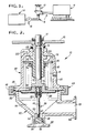
- FIG. 1 A fluid utilization system is illustrated in Fig. 1, which incorporates a downstream pressure regulating valve apparatus 10 constructed in accordance with a preferred embodiment of the present invention.
- the fluid system includes a dispensing apparatus 12 for measuring out and dispensing a fluid product into portions suitable for bottling or packaging.
- a source of fluid such as a tank or other container 14 of known construction is connected to the dispensing apparatus via a conduit 16, and a pump 18 is provided in the system to pressurize the fluid delivered to the dispensing apparatus.
- the pressure regulating valve apparatus 10 is interposed between the pump 18 and the dispensing apparatus 12 for controlling the pressure of the fluid downstream of the valve apparatus such that the fluid at the dispensing apparatus is maintained at a generally constant pressure. By providing such regulation of the pressure of the fluid at the dispensing apparatus 12, it is possible to provide an accurate dispensing operation.
- the pressure regulating valve apparatus 10 is shown in more detail in Fig. 2, and includes generally a lower housing 20 and an upper housing assembly 22.
- the lower housing 20 includes a lower interior space 24 including a surface adapted to be exposed to fluid being handled by the apparatus.
- the exposed surface of the interior space 24 is relatively smooth, preferably being formed by polishing with various polishing expedients until the roughness is less than about 15R a , which is an accepted roughness in the food industry for contact surfaces in fluid treatment devices.
- Inlet and outlet conduits 26, 28 are formed in the lower housing 20 which are each in communication with the lower interior space 24 and which are offset from one another, preferably by an angle of about ninety degrees.
- the inlet and outlet conduits 26, 28 include interior surfaces which, like the surface of the lower interior space 24, are polished to a surface roughness accepted by the food industry, and the inlet conduit 26 includes a constriction 30 having a function described below.
- each conduit 26, 28 is preferably provided with a flange 32, 34 adjacent a termination end thereof which permits attachment of the apparatus 10 to the conduit 16 of the fluid handling system.
- Other known connection expedients, such as butt welding may, of course, be used.
- a flange 36 is formed in the lower housing 20 adjacent an open end of the lower interior space 24 located opposite the inlet conduit 26, and defines a diaphragm bearing surface on which a diaphragm 38 is seated when the apparatus is assembled.
- the diaphragm 38 is formed of a relatively resilient material such as a food grade rubber, and is of a thickness less than about 40/1000 of an inch. This thickness may vary depending upon the loads to be experienced by the diaphragm during use and the types of materials available for use in the diaphragm.
- the surface of the diaphragm 38 which is exposed to the lower interior space 24 is preferably very smooth, having a roughness found acceptable for such uses by the food industry, e.g. less than about 15R a .
- the upper housing assembly 22 includes an upper housing 40 which is also provided with a flange 42 of a size corresponding to the size of the flange 36.
- the upper housing 40 is adapted to mate with the lower housing 20 with the flanges 36, 42 opposing one another, and with the diaphragm 38 therebetween.
- a circular ring clamp 44 of conventional construction is used to secure the housings 20, 40 and diaphragm 38 together.
- the upper housing 40 includes an upper interior space 46 that is separated from the lower interior space 24 by the diaphragm 38 when the apparatus is assembled such that the diaphragm and the lower interior space together define a fluid receiving cavity and the upper interior space 46 is isolated from contact with the fluid being handled by the apparatus.
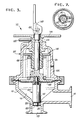
- the ring clamp 44 is illustrated in more detail in Fig. 4, and includes a plurality of clamp sections 48 and securing means for securing the clamp in place on the apparatus.
- the securing means includes a threaded rod 50, which is pivotally supported on one of the clamp sections 48 by a transverse pin 52, and a wing nut 54 or the like received on the threaded rod.
- a valve 56 is provided within the fluid receiving cavity and includes a valve closure member 58 disposed in the inlet conduit 26 opposite the constriction 30 from the fluid receiving cavity, and a lower stem element 60 extending between the valve closure member 58 and the diaphragm 38 so that the closure member and diaphragm are movable together.
- the closure member 58 is in a flow-permitting position such as that shown in Fig. 2, wherein the closure member is separated from the constriction 30 by a distance sufficient to permit the flow of fluid around the closure member and into the fluid receiving cavity.
- the closure member 58 is moved into a flow-preventing position in which the closure member seats against the constriction 30 to prevent the flow of fluid into the fluid receiving cavity.
- the closure member 58 is formed of a food grade material, preferably plastic, and is attached to the lower stem element 60 by a suitable adhesive which may be applied between a recess 62 of the closure member 58 and a relatively small diameter protrusion 64 formed on the end of the lower stem element 60.
- the closure member 58 includes a plurality of radially extending fingers 66 which center the closure member within the inlet conduit 26 while permitting fluid to flow around the closure member.
- the stem element 60 is illustrated in Fig. 2, and is also preferably formed of a food grade material such as a food grade plastic.
- the stem element is provided with one or more ridges 68 adjacent the diaphragm-engaging end thereof. These ridges 68 provide a secure connection between the stem element 60 and a central hub 70 of the diaphragm 38 when the diaphragm is fastened or molded to the stem element.
- An upper stem element 72 is also connected to the central hub 70 of the diaphragm 38 and extends in a direction opposite to the direction in which the lower stem element 60 extends.
- the upper stem element 72 extends through the upper interior space 46 and includes an end located outside of the upper housing 40 such that the position of the diaphragm 38, and thus the closure member 58, may be confirmed simply by noting the position of the end of the upper stem element relative to the upper housing.
- the upper stem element includes a bearing plate 74 in contact with the diaphragm 38 and adapted to bear against the diaphragm under the force of a pressure regulating means.
- This regulating means includes a compression spring 76 disposed within the upper interior space collinear with the upper stem element.
- the compression spring 76 is adapted to exert a predetermined compression load on the diaphragm 38 via the bearing plate 74 such that the diaphragm is normally biased toward the lower interior space 24 and the closure member 58 is retained in the flow-permitting position.
- Adjustment means are provided on the upper housing assembly 22 for adjusting the magnitude of the force exerted on the diaphragm 38 by the compression spring 76.
- the adjustment means includes an axially movable collar 78 that is retained against rotational movement within the upper interior space 46 of the housing 40 by two radially extending tabs 80, shown in Fig. 4, which ride in a pair of axial grooves 82 formed in the upper housing.
- the adjustment means also includes a rotatable sleeve 84 interposed between the axially movable collar 78 and the upper stem element 72 and being freely rotatable relative to the upper stem element.
- the sleeve 84 and collar 78 are threaded and cooperate during rotation of the sleeve to adjust the axial position of the collar within the upper housing 40.
- a flange 86 is formed on the sleeve 84 intermediate the ends thereof which prevents the sleeve from moving through an opening 88 in the upper housing. Axial movement of the sleeve in the opposite direction is prevented by the force exerted on the sleeve by the compression spring 76.
- a handle 90 is provided which is fixed to the sleeve 84 for rotation therewith.
- the handle 90 may be provided with a central opening having a square cross-sectional shape corresponding to a square section of the sleeve so that rotation of the handle translates into rotation of the sleeve 84.
- Limit stop means are provided in the upper housing assembly 22 for limiting the movement of the diaphragm 38 in the direction of the force of the pressure regulating means.
- This limit stop means is necessary to prevent the compression spring 76 from pushing completely through the diaphragm material and into the lower interior space 24, and includes a pin or protrusion 92 at the end of the upper stem element 72 which is adapted to abut the top end of the sleeve 84 when the limit position of the valve closure member 58 is reached.
- the pin or protrusion 92 is out of contact with the sleeve 84 and is elevated above the upper housing 40 by a noticeable height which serves as an indication of the closed position of the closure member 58.
- a further pin 94 is provided on the upper housing assembly 22 which may be positioned in a hole 96 formed in the sleeve, as shown in Fig. 5, and which also may engage a groove 98 formed in the upper stem element 72 in order to permit the upper stem element to be locked in the flow-permitting position.
- the pin 94 is removed from the hole 96 in the sleeve 84 and may be stored in an additional opening 100 provided on the upper housing.
- valve closure member 58 is normally biased in the flow-permitting position such that fluid under pressure enters the fluid receiving cavity via the inlet conduit 26 and exits the cavity through the outlet conduit 28.
- This fluid is used in some known type of fluid handling equipment downstream of the valve apparatus wherein it is desired that the fluid be maintained at a certain substantially constant pressure.
- the handle 90 is rotated in the appropriate direction in order to reposition the collar 78 within the upper interior space 46. If the collar 78 is moved upward away from the spring 76, the spring is relaxed and the stored energy within the spring is reduced such that less force is exerted on the diaphragm 38. By making this adjustment, less pressure is required within the fluid receiving cavity to cause movement of the diaphragm 38 and closure member 58 to the flow-preventing position.
- the apparatus is constructed with a fluid receiving cavity which is generally free of mechanical parts and which is defined by walls having a polished surface, no voids or interstices are presented to fluid passing through the apparatus which might cause the fluid to stagnate or settle in dead spots. As mentioned above, such stagnation or settling of many ingestible fluids permits solidification to occur or encourages germ growth which adversely effects the quality of the fluids.
- Another benefit achieved through the provision of the apparatus of the preferred embodiment resides in the ease of assembly and disassembly of the apparatus. By providing means for easily breaking the apparatus down into several parts, cleaning of the apparatus is simplified such that maintenance personnel are able to clean the parts more thoroughly than if the apparatus was cleaned in place in the system.
- the clamp 44 is first removed permitting the upper housing assembly 22 to be removed from the lower housing 20, and allowing the upper stem element 72 to be removed from the hub 70 of the diaphragm 38. Thereafter, the lower interior space 24 may be accessed for cleaning by folding back the diaphragm 38 or by pulling the diaphragm along with the lower stem element 60 and closure member 58 through the inlet conduit 26.
- the upper housing assembly 22 may be further broken down by removing the limit stop pin 92 from the upper stem element 72 and the open-lock pin 94 from the sleeve 84, and sliding the upper stem element through the opening 88. Once the upper stem element 72 is removed, the handle 90, sleeve 84, collar 78 and spring 76 may be slid from the upper stem element 72 so that the device is substantially completely broken down.
- the diaphragm 38 is locked in the flow-permitting position while the compression spring 76, collar 78, and sleeve 84 are left in their respective adjusted positions so that the pressure level at which the spring is set remains unchanged. Thereafter, when the pin 94 is removed, the apparatus returns to a proper regulating position.
- FIG. 3 An upstream pressure regulating apparatus 110 constructed in accordance with another aspect of the invention is illustrated in Fig. 3. This apparatus is similar to the downstream pressure regulating apparatus 10 discussed above except for several modifications permitting adaptation of the apparatus 110 for use in controlling the pressure of fluid upstream of the apparatus rather than the downstream pressure.
- an inlet conduit 112 enters a lower interior space 114 through the side of a lower housing 116 and an outlet conduit 118 is provided at the bottom of the housing and is substantially perpendicular to the inlet conduit 112.
- the outlet conduit 118 includes a constriction 120 adjacent the lower interior space 114.
- An upper housing assembly 122 is provided with an upper housing 124 which includes an interior space 126 that opposes the lower interior space 114 when assembled.
- a deformable diaphragm 128 separates the interior spaces 114, 126 so that a fluid receiving cavity is defined by the lower interior space and the diaphragm.
- a valve 130 includes a valve closure member 132 disposed in the fluid receiving cavity opposite the constriction 120 from the outlet conduit 118.
- the valve closure member 132 includes an angled closure surface 134 adapted to contact the constriction 120 to prevent the flow of fluid through the outlet conduit 118 when in a flow-preventing position.
- the closure member 132 is connected to the diaphragm 128 so that the closure member and diaphragm are movable together between a flow-permitting position in which the closure member is separated from the constriction 120 and a flow-preventing position in which the closure member is in engagement with the constriction.
- the diaphragm 38 is locked in the flow-permitting position while the compression spring 76, collar 78, and sleeve 84 are left in their respective adjusted positions so that the pressure level at which the spring is set remains unchanged. Thereafter, when the pin 94 is removed, the apparatus returns to a proper pressure regulating position.
- An upper stem element 136 connects to the diaphragm 128 and extends through the upper interior space 126.
- the upper stem element 136 includes an upper end disposed exterior of the upper housing 124.
- the upper housing assembly 122 further includes a pressure regulating spring 138 for exerting a force on the diaphragm 128 in a direction toward the lower interior space 114 such that the closure member 132 is normally biased toward the flow-preventing position.
- the apparatus 110 prevents the flow of fluid through the outlet conduit 118 unless and until the pressure in the fluid receiving cavity, and thus the inlet conduit 112, is at a pressure above a minimum threshold required to lift the diaphragm 128 and closure member 132 against the force of the compression spring 138 away from contact with the constriction 120.
- a lower end of the closure member 132 defines a plurality of radially extending centering arms 140 which align the closure member with the constriction 120 while permitting flow past the closure member when the angled closure surface 134 is out of contact with the constriction 120.
- Regulating adjustment means are provided, as in the downstream apparatus, for adjusting the force exerted on the diaphragm by the compression spring 138, and includes a collar 142, sleeve 144 and handle 146 as described above with reference to the apparatus 10.
- closure member opening means are provided to permit manual movement of the closure member 132 and diaphragm 128 to the flow-permitting position.
- a cam lever 148 is provided at the upper end of the stem element 136, and is pivotal about a pin 150 so that, upon pivoting of the cam lever 148, the stem element 136 is raised relative to a sleeve 144 of the regulating adjustment means.
- This movement of the stem element 136 pulls the diaphragm 128 and closure member 132 away from the constriction 120 to the flow-permitting position and a pin 152 may be used to lock the stem element 136 in place. Thereafter, cleaning of the fluid receiving cavity may be carried out without upsetting the present position of the pressure regulating means.
Landscapes
- Physics & Mathematics (AREA)
- Fluid Mechanics (AREA)
- General Physics & Mathematics (AREA)
- Engineering & Computer Science (AREA)
- Automation & Control Theory (AREA)
- Control Of Fluid Pressure (AREA)
- Safety Valves (AREA)
Applications Claiming Priority (2)
| Application Number | Priority Date | Filing Date | Title |
|---|---|---|---|
| US508364 | 1983-06-27 | ||
| US07/508,364 US5070901A (en) | 1990-04-12 | 1990-04-12 | Pressure regulating valve apparatus |
Publications (1)
| Publication Number | Publication Date |
|---|---|
| EP0451326A1 true EP0451326A1 (de) | 1991-10-16 |
Family
ID=24022457
Family Applications (1)
| Application Number | Title | Priority Date | Filing Date |
|---|---|---|---|
| EP19900118645 Withdrawn EP0451326A1 (de) | 1990-04-12 | 1990-09-28 | Druckregulierventilvorrichtung |
Country Status (3)
| Country | Link |
|---|---|
| US (1) | US5070901A (de) |
| EP (1) | EP0451326A1 (de) |
| JP (1) | JPH044373A (de) |
Cited By (3)
| Publication number | Priority date | Publication date | Assignee | Title |
|---|---|---|---|---|
| WO1994021949A1 (en) * | 1993-03-19 | 1994-09-29 | Tour & Andersson Ab | Self-actuating control valve |
| EP0650109A1 (de) * | 1993-10-09 | 1995-04-26 | Hans Sasserath & Co Kg | Druckminderer |
| WO2001094818A1 (en) * | 2000-06-05 | 2001-12-13 | Tour & Andersson Hydronics Ab | Differential pressure regulator |
Families Citing this family (8)
| Publication number | Priority date | Publication date | Assignee | Title |
|---|---|---|---|---|
| US5141022A (en) * | 1990-04-12 | 1992-08-25 | Cashco, Inc | Pressure regulating valve apparatus |
| US5492146A (en) * | 1992-09-02 | 1996-02-20 | Richards Industries, Inc. | Pressure regulators |
| US5415328A (en) * | 1993-02-18 | 1995-05-16 | Kyowa Industrial Co., Ltd. | Spray mechanism of aerosol product |
| US6536466B1 (en) * | 1998-09-04 | 2003-03-25 | Wanner Engineering | Pressure regulator apparatus |
| US6892755B2 (en) * | 2003-02-28 | 2005-05-17 | Baxter International Inc. | Pressure regulator for infusor |
| US6929026B1 (en) | 2003-03-28 | 2005-08-16 | Joseph Wilfred Arlinghaus, Jr. | Sanitary liquid pressure regulator |
| FR2899210A1 (fr) * | 2006-03-30 | 2007-10-05 | Ad Venta Sarl | Composant pneumatique pour la micro-diffusion controlee de gaz |
| TWI392988B (zh) * | 2007-12-07 | 2013-04-11 | Nissan Tanaka Corp | 壓力調整閥 |
Citations (4)
| Publication number | Priority date | Publication date | Assignee | Title |
|---|---|---|---|---|
| GB1184658A (en) * | 1967-10-03 | 1970-03-18 | Sperryn And Company Ltd | Improvements relating to Valves for Controlling Fluid Flow. |
| GB1284161A (en) * | 1969-06-26 | 1972-08-02 | Tetra Pak Internat Ab | Improvements in and relating to fluid-flow control means |
| DE2519828A1 (de) * | 1974-05-06 | 1975-11-20 | Auto Control Tap Of Canada Ltd | Fluessigkeitsabgabevorrichtung |
| DE2202792C2 (de) * | 1972-01-21 | 1983-11-17 | Honeywell-Braukmann GmbH, 6950 Mosbach | Druckminderer |
Family Cites Families (18)
| Publication number | Priority date | Publication date | Assignee | Title |
|---|---|---|---|---|
| US392447A (en) * | 1888-11-06 | Wilhelm meter | ||
| US189683A (en) * | 1877-04-17 | Improvement in gas-regulators | ||
| US1770912A (en) * | 1924-07-23 | 1930-07-22 | Oxweld Acetylene Company Inc | Relief valve |
| US1620322A (en) * | 1926-11-05 | 1927-03-08 | Fisher Governor Co | Pressure and vacuum control valve |
| US2315512A (en) * | 1939-03-08 | 1943-04-06 | Everson Roy Blair | Chlorine feeding device |
| US2593557A (en) * | 1947-09-26 | 1952-04-22 | Air Reduction | Pilot controlled gas pressure regulator |
| US2571433A (en) * | 1948-03-23 | 1951-10-16 | Joseph L Fine | Beverage dispensing receptacle |
| US2854025A (en) * | 1954-08-18 | 1958-09-30 | A W Cash Valve Mfg Corp | Automatic back pressure control valve |
| US2895640A (en) * | 1955-02-17 | 1959-07-21 | Mine Safety Appliances Co | Gas dispensing apparatus |
| US3374803A (en) * | 1965-06-17 | 1968-03-26 | Treffle J. Leveque | Volume and flow control device |
| US3376793A (en) * | 1965-10-11 | 1968-04-09 | Papadia | Hydraulic flow regulating apparatus |
| US3370215A (en) * | 1966-02-09 | 1968-02-20 | Basic Inc | Step up cycloconverter with harmonic distortion reducing means |
| US3481363A (en) * | 1967-08-18 | 1969-12-02 | Itt | Combination pressure regulator and shutoff valve |
| GB1281435A (en) * | 1969-04-01 | 1972-07-12 | Companion Heaters Pty | Improved gas control valve |
| US3576193A (en) * | 1969-06-11 | 1971-04-27 | Bendix Corp | High flow regulating and relief valve |
| US3732889A (en) * | 1971-04-08 | 1973-05-15 | Hydr O Matic Pump Co | Air relief valve assembly |
| US3747629A (en) * | 1972-06-28 | 1973-07-24 | Essex International Inc | Convertible fluid pressure regulator |
| US3948419A (en) * | 1974-08-01 | 1976-04-06 | Concession Service Corporation | Beverage fluid flow controller |
-
1990
- 1990-04-12 US US07/508,364 patent/US5070901A/en not_active Expired - Lifetime
- 1990-09-28 EP EP19900118645 patent/EP0451326A1/de not_active Withdrawn
- 1990-11-16 JP JP2311243A patent/JPH044373A/ja active Pending
Patent Citations (4)
| Publication number | Priority date | Publication date | Assignee | Title |
|---|---|---|---|---|
| GB1184658A (en) * | 1967-10-03 | 1970-03-18 | Sperryn And Company Ltd | Improvements relating to Valves for Controlling Fluid Flow. |
| GB1284161A (en) * | 1969-06-26 | 1972-08-02 | Tetra Pak Internat Ab | Improvements in and relating to fluid-flow control means |
| DE2202792C2 (de) * | 1972-01-21 | 1983-11-17 | Honeywell-Braukmann GmbH, 6950 Mosbach | Druckminderer |
| DE2519828A1 (de) * | 1974-05-06 | 1975-11-20 | Auto Control Tap Of Canada Ltd | Fluessigkeitsabgabevorrichtung |
Cited By (3)
| Publication number | Priority date | Publication date | Assignee | Title |
|---|---|---|---|---|
| WO1994021949A1 (en) * | 1993-03-19 | 1994-09-29 | Tour & Andersson Ab | Self-actuating control valve |
| EP0650109A1 (de) * | 1993-10-09 | 1995-04-26 | Hans Sasserath & Co Kg | Druckminderer |
| WO2001094818A1 (en) * | 2000-06-05 | 2001-12-13 | Tour & Andersson Hydronics Ab | Differential pressure regulator |
Also Published As
| Publication number | Publication date |
|---|---|
| JPH044373A (ja) | 1992-01-08 |
| US5070901A (en) | 1991-12-10 |
Similar Documents
| Publication | Publication Date | Title |
|---|---|---|
| US5141022A (en) | Pressure regulating valve apparatus | |
| US5070901A (en) | Pressure regulating valve apparatus | |
| US4567924A (en) | Aircraft under-wing fueling nozzle system | |
| US20060065868A1 (en) | Diaphragm valve | |
| US3561471A (en) | Safety valve | |
| CN1118855A (zh) | 气体分配控制装置和具有此装置的气瓶 | |
| EP2425157B1 (de) | Selbstausrichtender federsitz für einen fluidregler und einen selbstausrichtenden federsitz umfassender fluidregler | |
| CA2645506A1 (en) | Pressure reducing regulator with adjustable feature | |
| US4637439A (en) | Mini-regulator valve assembly | |
| US3457837A (en) | Controller for pneumatically-operated hoists | |
| EP0348035A2 (de) | Hochtemperatur-Sicherheitsventil | |
| NL8100597A (nl) | Drukregelaar. | |
| US5492146A (en) | Pressure regulators | |
| HUT75924A (en) | Mixer valve operated by one handle | |
| US4614481A (en) | Pump with replaceable cartridge | |
| US4375882A (en) | In-line flow control apparatus | |
| AU2002352793B2 (en) | Pneumatic pressure regulator assembly | |
| US5704589A (en) | Yoke for mounting on a gas tank | |
| WO1998030859A1 (en) | Gas pressure regulator for a paintball gun having additional overpressure vent valve | |
| EP0689652B2 (de) | Automatisches steuerventil | |
| US11692634B2 (en) | Bypass valve assembly with integrated flow control valve | |
| US10353404B1 (en) | Fluid dispenser and evacuator | |
| US5421547A (en) | Inline valve | |
| GB2289931A (en) | Two-stage regulator | |
| US10351413B1 (en) | Fluid dispenser having pressure regulator |
Legal Events
| Date | Code | Title | Description |
|---|---|---|---|
| PUAI | Public reference made under article 153(3) epc to a published international application that has entered the european phase |
Free format text: ORIGINAL CODE: 0009012 |
|
| AK | Designated contracting states |
Kind code of ref document: A1 Designated state(s): AT BE CH DE DK ES FR GB GR IT LI LU NL SE |
|
| 17P | Request for examination filed |
Effective date: 19911130 |
|
| 17Q | First examination report despatched |
Effective date: 19930514 |
|
| STAA | Information on the status of an ep patent application or granted ep patent |
Free format text: STATUS: THE APPLICATION IS DEEMED TO BE WITHDRAWN |
|
| 18D | Application deemed to be withdrawn |
Effective date: 19930925 |