EP0451335A1 - Dispositif d'entraînement de marteau de sonnerie - Google Patents
Dispositif d'entraînement de marteau de sonnerie Download PDFInfo
- Publication number
- EP0451335A1 EP0451335A1 EP90122014A EP90122014A EP0451335A1 EP 0451335 A1 EP0451335 A1 EP 0451335A1 EP 90122014 A EP90122014 A EP 90122014A EP 90122014 A EP90122014 A EP 90122014A EP 0451335 A1 EP0451335 A1 EP 0451335A1
- Authority
- EP
- European Patent Office
- Prior art keywords
- stop
- lever
- adjusting
- axis
- gong
- Prior art date
- Legal status (The legal status is an assumption and is not a legal conclusion. Google has not performed a legal analysis and makes no representation as to the accuracy of the status listed.)
- Withdrawn
Links
- 230000003247 decreasing effect Effects 0.000 description 1
- 238000000034 method Methods 0.000 description 1
- 230000000284 resting effect Effects 0.000 description 1
Images

Classifications
-
- G—PHYSICS
- G04—HOROLOGY
- G04B—MECHANICALLY-DRIVEN CLOCKS OR WATCHES; MECHANICAL PARTS OF CLOCKS OR WATCHES IN GENERAL; TIME PIECES USING THE POSITION OF THE SUN, MOON OR STARS
- G04B21/00—Indicating the time by acoustic means
- G04B21/02—Regular striking mechanisms giving the full hour, half hour or quarter hour
- G04B21/06—Details of striking mechanisms, e.g. hammer, fan governor
-
- G—PHYSICS
- G04—HOROLOGY
- G04B—MECHANICALLY-DRIVEN CLOCKS OR WATCHES; MECHANICAL PARTS OF CLOCKS OR WATCHES IN GENERAL; TIME PIECES USING THE POSITION OF THE SUN, MOON OR STARS
- G04B21/00—Indicating the time by acoustic means
- G04B21/02—Regular striking mechanisms giving the full hour, half hour or quarter hour
- G04B21/12—Reiterating watches or clocks
Definitions
- the invention relates to a stop device for a gong spring of a watch, in particular a repeater watch, with a gong spring arranged on a circuit board, against which one end provided with a stop hammer of a stop lever which can be pivoted about a pivot axis can be moved, with an end stop acting on the stop lever an axis between a basic position and a clamping position of the intermediate lever, which can be pivotably attacked, by means of which the stop lever can be moved against a spring force from a basic position in which the stop hammer is at a short distance from the gong to a clamping position remote from the gong, with an adjustable elastic stop on which the The stop lever in the basic position or the intermediate lever in the basic position is in contact and by means of which the distance of the stop hammer from the gong can be determined in the basic position.
- the stop lever is moved from the tensioned position with current into the basic position by a spring force.
- the swing must be large to deform the elastic stop so far that the hammer can hit the tonearm.
- this requires a relatively small distance between the stop hammer and the gong.
- this distance must not be too small either, since otherwise the gong spring, which is set in vibration by the striking stop hammer, comes into contact with the striking hammer, which is moved back somewhat by the elastically deforming stop, and the vibrations of the gong spring are thereby damped.
- the elastic stop is adjustable.
- the object of the invention is therefore to design a stop device of the type mentioned in such a way that its stop is adjustable in a simple and easy manner ensuring an optimal sound of the gong spring.
- the stop is arranged in an adjustment lever pivotally adjustable about an axis, which is supported on an arranged on the board at a distance from the axis, rotatable about an eccentric axis of rotation and engaging in a recess of the adjusting lever.
- the elastic stop can be a spring arm and form the stop surface at its free end.
- the eccentric has a circular adjusting head with an axis eccentric to the axis of rotation, which engages in a groove formed approximately radially to the axis of the adjusting lever in the adjusting lever, the width of which corresponds approximately to the diameter of the adjusting head.
- the eccentric preferably has a mounting pin which forms the axis of rotation and which can be press-fitted into a hole in the board.
- the adjusting head can have a screw slot on its end face facing away from the mounting pin.
- the adjusting lever can be locked against rotation in its setting position. This is possible on the one hand because the adjusting lever has a threaded hole, in which a set screw can be arranged, which can be supported with the free end of its shaft on the board.
- a further embodiment consists in that the adjusting lever has a bore through which an adjusting screw of smaller diameter can be passed and screwed into a threaded hole in the board, the head of the adjusting screw being able to be supported on the adjusting lever.
- the adjusting lever can be formed in one piece with a tension spring arm, through the free end of which the stop lever is urged into the tension position remote from the spring.
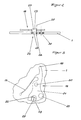
- the stop device shown is arranged on a circuit board 1 and has a gong spring 2 with a tonearm 3 fastened on the circuit board 1.
- a with one end pivotable about an axis 4 on the board 1 stop 5 has its other free end a stop hammer 6, which is in the basic position shown a short distance from the tonearm 3.
- a clamping arm 7 is firmly connected to the stop lever 5.
- the scoop 12 bears against the arm 11 via a projecting drive pin 13.
- the intermediate lever 9 is also pivoted via the drive pin 13 .
- the arm 10, which engages on the tension arm 7, moves the stop lever 5 counterclockwise from its illustrated basic position into a tension position until the engaging tooth 14 slips over the tip of the mandrel 16 and releases the creator 12.
- tension spring arm 17 is tensioned during this movement and moves after release of the scoop 12 through the tooth 14 the tension arm and thus the stop lever 5 and Hammer 6 back with a swing towards the basic position.
- the intermediate lever 9 rests with its arm 10 to an elastic stop 18, which thereby determines the distance between the tonearm 3 and the stop hammer 6.
- the stop 18 designed as a spring arm is elastically deformed to such an extent that the distance between the tonearm 3 and the stop hammer 6 is overcome and the stop hammer 6 strikes the tonearm 3. This causes it to vibrate and produces a sound.
- the elasticity of the stop 18 then immediately moves the stop lever 5 and thus the stop hammer 6 away from the tonearm 3 so that it can swing freely.
- Both the tension spring arm 17 and the stop 18 are integrally formed with an adjusting lever 19.
- the adjusting lever 19 is a two-armed lever which is freely pivotable about an axis 20, one lever arm of which is formed by the stop 18 and the second lever arm of which is on the adjusting arm 21.
- a groove 22 is formed which extends approximately radially to the axis 20, the width of which corresponds approximately to the diameter of an adjusting head 23 of an eccentric 24 guided in the groove 22.
- the eccentric 24 has an assembly pin 25 which projects eccentrically to the axis 20 and which is press-fitted into a bore 26 in the circuit board 1.
- the adjusting head 23 On its side facing away from the mounting pin 25, the adjusting head 23 is provided with a screw slot 27 into which a screwdriver is inserted and the eccentric 24 can be rotated in the bore 26 while overcoming the frictional forces of the mounting pin 25.
- the adjusting lever 19 is pivoted about the axis 20. This also leads to a change in position of the stop 18 and the intermediate lever 9 resting thereon. This correspondingly pivots the stop lever 5 via the tensioning arm 7 and changes the distance between the tonearm 3 and the stop hammer 6.
- the newly adjusted basic position can be secured by an adjusting screw 28 which extends through a fixing hole 29 of larger diameter of the adjusting lever 19 and is screwed with its threaded shaft into a threaded hole 30 on the circuit board 1.
- the head 31 of the adjusting screw 28 comes to bear on the side facing away from the circuit board 1 against the adjusting lever 19 and holds it firmly in this position.
Landscapes
- Physics & Mathematics (AREA)
- General Physics & Mathematics (AREA)
- Electromechanical Clocks (AREA)
- Portable Nailing Machines And Staplers (AREA)
Applications Claiming Priority (2)
| Application Number | Priority Date | Filing Date | Title |
|---|---|---|---|
| DE19904012026 DE4012026A1 (de) | 1990-04-13 | 1990-04-13 | Anschlagvorrichtung |
| DE4012026 | 1990-04-13 |
Publications (1)
| Publication Number | Publication Date |
|---|---|
| EP0451335A1 true EP0451335A1 (fr) | 1991-10-16 |
Family
ID=6404379
Family Applications (1)
| Application Number | Title | Priority Date | Filing Date |
|---|---|---|---|
| EP90122014A Withdrawn EP0451335A1 (fr) | 1990-04-13 | 1990-11-17 | Dispositif d'entraînement de marteau de sonnerie |
Country Status (2)
| Country | Link |
|---|---|
| EP (1) | EP0451335A1 (fr) |
| DE (1) | DE4012026A1 (fr) |
Cited By (6)
| Publication number | Priority date | Publication date | Assignee | Title |
|---|---|---|---|---|
| EP1760549A1 (fr) * | 2005-09-01 | 2007-03-07 | Montres Journe SA | Timbre pour mécanisme de sonnerie de pièce d'horlogerie |
| CN102109808A (zh) * | 2009-12-24 | 2011-06-29 | 宝玑表有限公司 | 用于表的报时机构 |
| CN102629100A (zh) * | 2011-02-07 | 2012-08-08 | 帝舵钟表有限公司 | 手表机芯部件 |
| US20160274543A1 (en) * | 2015-03-18 | 2016-09-22 | Glashuetter Uhrenbetrieb Gmbh | Striking mechanism comprising a hammer with an elastic adjustable stop |
| EP2048548A3 (fr) * | 2007-10-10 | 2016-11-30 | Richemont International S.A. | Marteau pour mécanisme d'horlogerie, mécanisme d'horlogerie, notamment mécanisme de sonnerie, en étant équipé, et pièce d'horlogerie les comportant |
| CN110543091A (zh) * | 2018-05-28 | 2019-12-06 | 布朗潘有限公司 | 具有报时机构和防释放装置的钟表 |
Families Citing this family (2)
| Publication number | Priority date | Publication date | Assignee | Title |
|---|---|---|---|---|
| EP2362278B1 (fr) * | 2010-02-26 | 2016-10-12 | Montres Breguet SA | Marteau d'un mécanisme de sonnerie d'une montre |
| EP3869280B1 (fr) * | 2020-02-19 | 2024-04-17 | Montres Breguet S.A. | Mecanisme d'affichage d'horlogerie |
Citations (2)
| Publication number | Priority date | Publication date | Assignee | Title |
|---|---|---|---|---|
| US1966002A (en) * | 1933-02-15 | 1934-07-10 | Ingraham E Co | Hammer-mechanism for audiblesignal clocks |
| CH633376A5 (en) * | 1977-05-06 | 1982-11-30 | Yarden Medical Eng Ltd | Appliance for setting the flow rate of a liquid |
-
1990
- 1990-04-13 DE DE19904012026 patent/DE4012026A1/de not_active Ceased
- 1990-11-17 EP EP90122014A patent/EP0451335A1/fr not_active Withdrawn
Patent Citations (2)
| Publication number | Priority date | Publication date | Assignee | Title |
|---|---|---|---|---|
| US1966002A (en) * | 1933-02-15 | 1934-07-10 | Ingraham E Co | Hammer-mechanism for audiblesignal clocks |
| CH633376A5 (en) * | 1977-05-06 | 1982-11-30 | Yarden Medical Eng Ltd | Appliance for setting the flow rate of a liquid |
Cited By (13)
| Publication number | Priority date | Publication date | Assignee | Title |
|---|---|---|---|---|
| EP1760549A1 (fr) * | 2005-09-01 | 2007-03-07 | Montres Journe SA | Timbre pour mécanisme de sonnerie de pièce d'horlogerie |
| EP2048548A3 (fr) * | 2007-10-10 | 2016-11-30 | Richemont International S.A. | Marteau pour mécanisme d'horlogerie, mécanisme d'horlogerie, notamment mécanisme de sonnerie, en étant équipé, et pièce d'horlogerie les comportant |
| CN102109808A (zh) * | 2009-12-24 | 2011-06-29 | 宝玑表有限公司 | 用于表的报时机构 |
| CH702424A1 (fr) * | 2009-12-24 | 2011-06-30 | Montres Breguet Sa | Mécanisme de sonnerie d'une montre. |
| CN102109808B (zh) * | 2009-12-24 | 2012-12-26 | 宝玑表有限公司 | 用于表的报时机构 |
| US8514669B2 (en) | 2009-12-24 | 2013-08-20 | Montres Breguet Sa | Strike mechanism for a watch |
| CN102629100B (zh) * | 2011-02-07 | 2016-03-02 | 帝舵钟表有限公司 | 手表机芯部件 |
| CN102629100A (zh) * | 2011-02-07 | 2012-08-08 | 帝舵钟表有限公司 | 手表机芯部件 |
| EP2485098B1 (fr) * | 2011-02-07 | 2021-11-03 | Montres Tudor S.A. | Pièce d'horlogerie |
| US20160274543A1 (en) * | 2015-03-18 | 2016-09-22 | Glashuetter Uhrenbetrieb Gmbh | Striking mechanism comprising a hammer with an elastic adjustable stop |
| US10067474B2 (en) * | 2015-03-18 | 2018-09-04 | Glashütter Uhrenbetrieb GmbH | Striking mechanism comprising a hammer with an elastic adjustable stop |
| CN110543091A (zh) * | 2018-05-28 | 2019-12-06 | 布朗潘有限公司 | 具有报时机构和防释放装置的钟表 |
| CN110543091B (zh) * | 2018-05-28 | 2021-02-26 | 布朗潘有限公司 | 具有报时机构和防释放装置的钟表 |
Also Published As
| Publication number | Publication date |
|---|---|
| DE4012026A1 (de) | 1991-10-17 |
Similar Documents
| Publication | Publication Date | Title |
|---|---|---|
| EP0451335A1 (fr) | Dispositif d'entraînement de marteau de sonnerie | |
| DE2725514C3 (de) | Uhrwerk fur eine Kalenderuhr | |
| DE2633968C3 (de) | Einstellvorrichtung für den optischen Block eines Scheinwerfers | |
| DE2702020C3 (de) | Uhrwerk | |
| DE10138123A1 (de) | Handwerkzeugmaschine mit vibrationsgedämpftem Handgriff | |
| DE4435704C2 (de) | Schwingsystem | |
| CH506116A (de) | Einstellvorrichtung in einem zeithaltenden Gerät | |
| DE1291406B (de) | Vorrichtung zur Betaetigung von elektrischen Kontakten | |
| EP0451336B1 (fr) | Dispositif de remontage à ressort | |
| DE1673710C (de) | Einstellvorrichtung zur Veränderung des Axialspiels einer in einer Brücke ge lagerten Welle | |
| DE2343392C3 (de) | Kniehebelzwinge | |
| DE702193C (de) | Auf eine gewuenschte Zeitdauer einstellbarer Kurzzeitschalter | |
| CH695223A5 (de) | Hemmung fuer ein Uhrwerk. | |
| AT164234B (de) | Elektromagnetisches Kleingerät mit Kippanker, insbesondere Kipprelais | |
| DE1548066C3 (de) | Elektromechanischer Antrieb für elektrische Uhren mit einer Drehspule | |
| DE489291C (de) | Vorrichtung zum Einstellen oder Nachregeln des Abstandes zwischen dem Anker und den Magnetpolen bei magnetischen Lautsprecherantriebssystemen | |
| DE1523847B2 (de) | Wecker-Uhrwerk | |
| DE497606C (de) | Elektromagnetische Pendeluhr | |
| DE102715C (fr) | ||
| DE2358262C3 (de) | Mit einer Anzeigevorrichtung versehene einstellbare Feldplatten-Anordnung | |
| DD212633B1 (de) | Verriegelte festspanneinrichtung, insbesondere fuer schallwandler in fernsprechhandapparaten | |
| DE940213C (de) | Lager, insbesondere fuer Schwing- und Wendefluegel von Fenstern | |
| DE687559C (de) | Empfangsvorrichtung fuer ferngesteuerte Anlagen | |
| DE1673729A1 (de) | Klinkengetriebe | |
| DE1447336A1 (de) | Geraetelagerung |
Legal Events
| Date | Code | Title | Description |
|---|---|---|---|
| PUAI | Public reference made under article 153(3) epc to a published international application that has entered the european phase |
Free format text: ORIGINAL CODE: 0009012 |
|
| 17P | Request for examination filed |
Effective date: 19910712 |
|
| AK | Designated contracting states |
Kind code of ref document: A1 Designated state(s): CH DE FR IT LI |
|
| 17Q | First examination report despatched |
Effective date: 19920910 |
|
| STAA | Information on the status of an ep patent application or granted ep patent |
Free format text: STATUS: THE APPLICATION IS DEEMED TO BE WITHDRAWN |
|
| 18D | Application deemed to be withdrawn |
Effective date: 19930323 |