EP0451340A1 - Repetieruhr - Google Patents
Repetieruhr Download PDFInfo
- Publication number
- EP0451340A1 EP0451340A1 EP90122019A EP90122019A EP0451340A1 EP 0451340 A1 EP0451340 A1 EP 0451340A1 EP 90122019 A EP90122019 A EP 90122019A EP 90122019 A EP90122019 A EP 90122019A EP 0451340 A1 EP0451340 A1 EP 0451340A1
- Authority
- EP
- European Patent Office
- Prior art keywords
- tonearm
- foot piece
- watch according
- repeater
- repeater watch
- Prior art date
- Legal status (The legal status is an assumption and is not a legal conclusion. Google has not performed a legal analysis and makes no representation as to the accuracy of the status listed.)
- Granted
Links
- 238000003466 welding Methods 0.000 claims abstract description 13
- 238000010276 construction Methods 0.000 description 1
- 230000006735 deficit Effects 0.000 description 1
Images

Classifications
-
- G—PHYSICS
- G04—HOROLOGY
- G04B—MECHANICALLY-DRIVEN CLOCKS OR WATCHES; MECHANICAL PARTS OF CLOCKS OR WATCHES IN GENERAL; TIME PIECES USING THE POSITION OF THE SUN, MOON OR STARS
- G04B21/00—Indicating the time by acoustic means
- G04B21/02—Regular striking mechanisms giving the full hour, half hour or quarter hour
- G04B21/08—Sounding bodies; Whistles; Musical apparatus
-
- G—PHYSICS
- G04—HOROLOGY
- G04B—MECHANICALLY-DRIVEN CLOCKS OR WATCHES; MECHANICAL PARTS OF CLOCKS OR WATCHES IN GENERAL; TIME PIECES USING THE POSITION OF THE SUN, MOON OR STARS
- G04B21/00—Indicating the time by acoustic means
- G04B21/02—Regular striking mechanisms giving the full hour, half hour or quarter hour
- G04B21/12—Reiterating watches or clocks
Definitions
- the invention relates to a repeater watch with a support plate arranged in a watch case, on which a foot piece of a gong spring can be fastened, the gong spring being a tonearm fastened at one end to the foot piece and projecting freely from the foot piece, which can be struck by a striking hammer. wherein the foot piece has a holding recess into which the tonearm projects with one end and is fastened.
- the gong spring is formed in one piece with the foot piece. This one-piece design makes the sound of the struck gong spring particularly good. However, it is disadvantageous that such a gong spring can only be produced with great effort and is therefore expensive.
- the object of the invention is therefore to provide a repeater watch according to the preamble, the simple Sounded gong spring that can be produced with a high degree of purity sounds.
- tonearm is connected to the foot piece by means of one or more welding spots.
- the welding spots are produced by means of laser welding. This changes the material structure of the tonearm and footpiece to the smallest possible extent. This means the least possible impairment of the swinging ability of the gong spring. This also contributes to the fact that the consistency of the material forming the connection and melted by the laser is very hard.
- the tonearm is preferably inserted without play in the holding recess.
- the holding recess is a holding slot, the width of which corresponds approximately to the width of the tonearm, then the tonearm is freely accessible for forming the welding spot.
- the tonearm may preferably have a circular cross section.
- the tonearm is particularly easy to oscillate and achieves a pure sound if it consists of a spring wire or another hardened material.
- the spot welding only slightly increases the hardening.
- the height of the holding slot can be greater than the height extension be the tonearm and the tonearm be arranged at a distance from the carrier board in the holding slot. This prevents the tonearm from touching the carrier board and affecting the sound.
- a simple and space-saving construction with several tonearms is achieved in that the foot piece has several holding recesses arranged side by side and / or one above the other to the level of the carrier board, in each of which a tonearm is arranged.
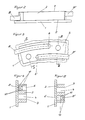
- a foot piece 2 is fastened in the edge area on the circular carrier board 1 shown in FIG 4 protrude into corresponding holding holes in the foot piece 2.
- the foot piece 2 consists of a ring segment of rectangular cross section arranged concentrically to the center of the carrier plate and lies with its bottom surface 5 on the carrier plate 1.
- two holding slots 6 and 6 ′ are formed, which extend approximately parallel to one another with a different radius to the center of the carrier board 1.
- each holding slot 6 and 6 ' which is directed in the circumferential direction, is closed, while the other end opens out in the circumferential direction in such a way that the two mouths are directed in the opposite direction outwards.
- the holding slots 6 and 6 ' are continuous from the bottom surface 5 to the top 7 of the foot piece 2 and have an approximately rectangular cross section.
- each holding slot 6 and 6 ' is arranged at its one end an annular tonearm 8 and 8' formed from a hardened spring wire with a round cross section, the thickness of the tonearms 8 and 8 'corresponding to the width of the corresponding holding slots 6 and 6'.
- the two tonearms 8 and 8 ' are arranged in different planes, each parallel to the plane of the carrier board 1, in such a way that that of the carrier board 1 closer tonearm 8 is at a distance from the carrier board 1.
- both stop hammers 11 and 11' can be pivoted in parallel planes to the carrier board 1 about pivot axes 9 and 9 'on the carrier board 1 in the area near the foot piece on the respectively assigned tonearm 8 and 8 ' attacks.
- the tonearms 8 and 8 ' are each connected to the foot piece 2 by four welding spots 10 produced by means of laser welding.
- two welding spots 10 are formed on the side of the tonearms 8 and 8 ′ closer to the bottom surface 5 and two welding spots 10 on the upper side 7.
- the pitch is essentially determined by the vibration length of the tonearms 8 and 8 '. After the tonearms 8 and 8 'have been welded in, the desired pitch can therefore be set by forming a cross-sectional reduction, preferably in the area of the tonearms 8 and 8' which protrudes directly from the foot piece. This material can be removed either mechanically or using a laser.
Landscapes
- Physics & Mathematics (AREA)
- General Physics & Mathematics (AREA)
- Engineering & Computer Science (AREA)
- Acoustics & Sound (AREA)
- Multimedia (AREA)
- Laser Beam Processing (AREA)
- Percussion Or Vibration Massage (AREA)
Abstract
Description
- Die Erfindung bezieht sich auf eine Repetieruhr mit einer in einem Uhrgehäuse angeordneten Trägerplatine, auf der ein Fußstück einer Tonfeder befestigbar ist, wobei die Tonfeder ein mit ihrem einen Ende am Fußstück befestigter und vom Fußstück frei wegragender Tonarm ist, der durch einen Anschlaghammer anschlagbar ist, wobei das Fußstück eine Halteausnehmung aufweist, in die der Tonarm mit seinem einen Ende hineinragt und befestigt ist.
- Bei bekannten Repetieruhren ist die Tonfeder einteilig mit dem Fußstück ausgebildet. Durch diese Einteiligkeit ist die Reinheit des Klanges der angeschlagenen Tonfeder besonders gut. Nachteilig ist aber, daß eine solche Tonfeder nur mit sehr großem Aufwand herstellbar und somit teuer ist.
- Aufgabe der Erfindung ist es daher, eine Repetieruhr nach dem Oberbegriff zu schaffen, deren auf einfache Weise herstellbare angeschlagene Tonfeder mit einem hohen Maß an Reinheit klingt.
- Diese Aufgabe wird erfindungsgemäß dadurch gelöst, daß der Tonarm mittels eines oder mehrerer Schweißpunkte mit dem Fußstück verbunden ist.
- Besonders vorteilhaft ist es dabei, wenn die Schweißpunkte mittels Laserschweißung hergestellt sind. Damit wird die Materialstruktur von Tonarm und Fußstück in nur geringstmöglichem Umfang verändert. Dies bedeutet eine geringstmögliche Beeinträchtigung der Schwingfähigkeit der Tonfeder. Dazu trägt auch bei, daß die Konsistenz des die Verbindung bildenden, durch den Laser geschmolzenen Materials sehr hart ist. Vorzugsweise ist dabei der Tonarm spielfrei in der Halteausnehmung eingesetzt.
- Ist die Halteausnehmung ein Halteschlitz, dessen Breite etwa der Breite des Tonarms entspricht, so ist der Tonarm zum Ausbilden des Schweißpunktes frei zugänglich.
- Der Tonarm kann vorzugsweise einen kreisförmigen Querschnitt aufweisen.
- Der Tonarm ist besonders gut schwingfähig und erzielt einen reinen Klang, wenn er aus einem Federdraht oder aus einem anderen gehärteten Werkstoff besteht. Die Härtung wird durch die Punktschweißung nur unwesentlich aufgehoben.
- Um das freie Schwingen des Tonarms zu gewährleisten, kann die Höhe des Halteschlitzes größer als die Höhenerstreckung des Tonarmes sein und der Tonarm mit einem Abstand zur Trägerplatine im Halteschlitz angeordnet sein. Damit ist eine den Klang beeinträchtigende Berührung der Trägerplatine durch den Tonarm vermieden.
- Ein einfacher und platzsparender Aufbau mit mehreren Tonarmen wird dadurch erreicht, daß das Fußstück mehrere zur Ebene der Trägerplatine nebeneinander und/oder übereinander angeordnete Halteausnehmungen aufweist, in denen jeweils ein Tonarm angeordnet ist.
- Ein Ausführungsbeispiel der Erfindung ist in der Zeichnung dargestellt und wird im folgenden näher beschrieben. Es zeigen
- Figur 1
- eine Draufsicht auf eine Trägerplatine mit Tonarmen, Fußstück und Anschlaghämmern,
- Figur 2
- eine vergrößerte Seitenansicht des Bereichs Fußstücks nach Figur 1,
- Figur 3
- eine vergrößerte Draufsicht des Bereichs des Fußstücks nach Figur 1,
- Figur 4
- einen Schnitt entlang der Linie A-A in Figur 3,
- Figur 5
- einen Schnitt entlang der Linie B-B in Figur 3.
- Im Randbereich ist auf der in Figur 1 dargestellten kreisförmigen Trägerplatine 1 ein Fußstück 2 befestigt, wobei an der Trägerplatine 1 befestigte Haltebolzen 4 in entsprechende Haltebohrungen des Fußstücks 2 ragen.
- Das Fußstück 2 besteht aus einem konzentrisch zur Mitte der Trägerplatine angeordneten Ringsegment rechteckigen Querschnitts und liegt mit seiner Bodenfläche 5 auf der Trägerplatine 1 auf. In dem Ringsegment sind zwei Halteschlitze 6 und 6' ausgebildet, die sich etwa parallel zueinander mit unterschiedlichem Radius zum Mittelpunkt der Trägerplatine 1 erstrecken.
- Das eine in Umfangsrichtung gerichtete Ende jedes Halteschlitzes 6 und 6' ist geschlossen, während das jeweils andere Ende in Umfangsrichtung nach außen mündet und zwar so, daß die beiden Mündungen entgegengesetzt nach außen gerichtet sind.
- Die Halteschlitze 6 und 6' sind von der Bodenfläche 5 bis zur Oberseite 7 des Fußstücks 2 durchgehend ausgebildet und besitzen einen etwa rechteckigen Querschnitt.
- In jeden Halteschlitz 6 und 6' ist mit seinem einen Ende ein ringförmiger, aus einem gehärteten Federdraht runden Querschnitts gebildeter Tonarm 8 bzw. 8' angeordnet, wobei die Dicke der Tonarme 8 und 8' der Breite der entsprechenden Halteschlitze 6 und 6' entspricht.
- Wie in den Figuren 2, 4 und 5 deutlich zu sehen ist, sind die beiden Tonarme 8 und 8' in unterschiedlichen, jeweils zur Ebene der Trägerplatine 1 parallelen Ebene angeordnet und zwar so, daß auch der der Trägerplatine 1 nähere Tonarm 8 sich in einem Abstand zur Trägerplatine 1 befindet.
- Durch die Anordnung der Tonarme 8 und 8' in unterschiedlichen Ebenen können beide in parallelen Ebenen zur Trägerplatine 1 um Schwenkachsen 9 bzw. 9' schwenkbar auf der Trägerplatine 1 angeordnete Anschlaghämmer 11 und 11' im fußstücknahen Bereich an dem jeweils zugeordneten Tonarm 8 bzw. 8' anschlagen.
- Wie in den Figuren 4 und 5 deutlich dargestellt ist, sind die Tonarme 8 und 8' jeweils durch vier mittels Laserschweißung hergestellter Schweißpunkte 10 mit dem Fußstück 2 verbunden. Dabei sind jeweils zwei Schweißpunkte 10 auf der der Bodenfläche 5 und zwei Schweißpunkte 10 auf der Oberseite 7 näheren Seite der Tonarme 8 und 8'ausgebildet.
- Die Tonhöhe wird wesentlich durch die Schwingungslänge der Tonarme 8 und 8' bestimmt. Nach Einschweißen der Tonarme 8 und 8' kann daher durch Ausbildung einer Querschnittsverringerung vorzugsweise im unmittelbar aus dem Fußstück herausragenden Bereich der Tonarme 8 bzw. 8' die jeweils gewünschte Tonhöhe eingestellt werden. Diese Materialabtragung kann entweder mechanisch oder aber auch mittels Laser erfolgen.
Claims (9)
- Repetieruhr mit einer in einem Uhrgehäuse angeordneten Trägerplatine, auf der ein Fußstück einer Tonfeder befestigbar ist, wobei die Tonfeder ein mit ihrem einen Ende am Fußstück befestigter und vom Fußstück frei wegragender Tonarm ist, der durch einen Anschlaghammer anschlagbar ist, wobei das Fußstück eine Halteausnehmung aufweist, in die der Tonarm mit seinem einen Ende hineinragt und befestigt ist, dadurch gekennzeichnet, daß der Tonarm 8, 8' mittels eines oder mehrerer Schweißpunkte (10) mit dem Fußstück (2) verbunden ist.
- Repetieruhr nach Anspruch 1, dadurch gekennzeichnet, daß die Schweißpunkte (10) mittels Laserschweißung hergestellt sind.
- Repetieruhr nach einem der vorhergehenden Ansprüche, dadurch gekennzeichnet, daß die Halteausnehmung ein Halteschlitz (6, 6') ist, dessen Breite etwa der Breite des Tonarms (8, 8') entspricht.
- Repetieruhr nach einem der vorhergehenden Ansprüche, dadurch gekennzeichnet, daß der Tonarm (8, 8') einen kreisförmigen Querschnitt aufweist.
- Repetieruhr nach einem der vorhergehenden Ansprüche, dadurch gekennzeichnet, daß der Tonarm (8, 8') aus einem Federdraht besteht.
- Repetieruhr nach einem der vorhergehenden Ansprüche, dadurch gekennzeichnet, daß der Tonarm aus einem gehärteten Werkstoff besteht.
- Repetieruhr nach Anspruch 3, dadurch gekennzeichnet, daß die Höhe des Halteschlitzes (6, 6') größer als die Höhenerstreckung des Tonarms (8, 8') ist und der Tonarm (8, 8') mit einem Abstand zur Trägerplatine (1) im Halteschlitz (6, 6') angeordnet ist.
- Repetieruhr nach einem der vorhergehenden Ansprüche, dadurch gekennzeichnet, daß das Fußstück (2) mehrere zur Ebene der Trägerplatine (1) nebeneinander und/oder übereinander angeordnete Halteausnehmungen aufweist, in denen jeweils ein Tonarm (8, 8') angeordnet ist.
- Repetieruhr nach einem der vorhergehenden Ansprüche, dadurch gekennzeichnet, daß der Tonarm (8, 8') an seinem unmittelbar aus dem Fußstück (2) herausragenden Bereich eine Querschnittsverringerung besitzt.
Applications Claiming Priority (2)
| Application Number | Priority Date | Filing Date | Title |
|---|---|---|---|
| DE4012059 | 1990-04-13 | ||
| DE4012059A DE4012059A1 (de) | 1990-04-13 | 1990-04-13 | Repetieruhr |
Publications (2)
| Publication Number | Publication Date |
|---|---|
| EP0451340A1 true EP0451340A1 (de) | 1991-10-16 |
| EP0451340B1 EP0451340B1 (de) | 1993-12-08 |
Family
ID=6404406
Family Applications (1)
| Application Number | Title | Priority Date | Filing Date |
|---|---|---|---|
| EP90122019A Expired - Lifetime EP0451340B1 (de) | 1990-04-13 | 1990-11-17 | Repetieruhr |
Country Status (2)
| Country | Link |
|---|---|
| EP (1) | EP0451340B1 (de) |
| DE (2) | DE4012059A1 (de) |
Cited By (6)
| Publication number | Priority date | Publication date | Assignee | Title |
|---|---|---|---|---|
| EP2034375A1 (de) * | 2007-09-05 | 2009-03-11 | Seiko Epson Corporation | Uhr und tragbare Vorrichtung |
| CH702145A1 (fr) * | 2009-11-03 | 2011-05-13 | Montres Breguet Sa | Timbre pour une sonnerie d'une piece d'horlogerie. |
| CN101154090B (zh) * | 2006-09-26 | 2011-06-15 | 宝玑表有限公司 | 带有撞击工件的表 |
| CN101441435B (zh) * | 2007-10-10 | 2013-10-23 | 历峰国际有限公司 | 锤、装有锤的钟表机构以及包含它们的计时器 |
| CN105093902A (zh) * | 2014-05-06 | 2015-11-25 | 布朗潘有限公司 | 用于从报时机构产生声音的组件 |
| CN111290230A (zh) * | 2018-12-06 | 2020-06-16 | 宝玑表有限公司 | 悬锤式敲击时计机械装置 |
Families Citing this family (2)
| Publication number | Priority date | Publication date | Assignee | Title |
|---|---|---|---|---|
| EP3657268B1 (de) * | 2018-11-22 | 2026-02-18 | Blancpain SA | Resonanzorgan für schlagwerkmechanismus einer armbanduhr oder einer spieluhr |
| EP3657267A1 (de) * | 2018-11-22 | 2020-05-27 | Blancpain SA | Resonanzorgan für schlagwerkmechanismus einer armbanduhr oder einer spieluhr |
Citations (6)
| Publication number | Priority date | Publication date | Assignee | Title |
|---|---|---|---|---|
| CH26599A (de) * | 1902-08-09 | 1903-09-30 | Friedrich Mauthe | Gongfeder |
| CH55452A (de) * | 1912-02-12 | 1912-08-16 | Baptiste Viglino | Verfahren zur Herstellung von Glocken |
| US1695087A (en) * | 1928-01-20 | 1928-12-11 | E Ingraham Co | Method of producing gong stands for clocks |
| US1704864A (en) * | 1924-12-31 | 1929-03-12 | Sessions Clock Co | Sounding mechanism for clocks |
| CH344955A (fr) * | 1958-10-17 | 1960-02-29 | D Horlogerie Angelus Stolz Fre | Montre-bracelet à répétition |
| FR1492672A (fr) * | 1965-09-14 | 1967-08-18 | Suisse Pour L Ind Horlogere Sa | Procédé de fabrication d'une pièce d'horlogerie et pièce d'horlogerie obtenue par la mise en oeuvre de ce procédé |
-
1990
- 1990-04-13 DE DE4012059A patent/DE4012059A1/de not_active Withdrawn
- 1990-11-17 DE DE90122019T patent/DE59003804D1/de not_active Expired - Fee Related
- 1990-11-17 EP EP90122019A patent/EP0451340B1/de not_active Expired - Lifetime
Patent Citations (6)
| Publication number | Priority date | Publication date | Assignee | Title |
|---|---|---|---|---|
| CH26599A (de) * | 1902-08-09 | 1903-09-30 | Friedrich Mauthe | Gongfeder |
| CH55452A (de) * | 1912-02-12 | 1912-08-16 | Baptiste Viglino | Verfahren zur Herstellung von Glocken |
| US1704864A (en) * | 1924-12-31 | 1929-03-12 | Sessions Clock Co | Sounding mechanism for clocks |
| US1695087A (en) * | 1928-01-20 | 1928-12-11 | E Ingraham Co | Method of producing gong stands for clocks |
| CH344955A (fr) * | 1958-10-17 | 1960-02-29 | D Horlogerie Angelus Stolz Fre | Montre-bracelet à répétition |
| FR1492672A (fr) * | 1965-09-14 | 1967-08-18 | Suisse Pour L Ind Horlogere Sa | Procédé de fabrication d'une pièce d'horlogerie et pièce d'horlogerie obtenue par la mise en oeuvre de ce procédé |
Cited By (10)
| Publication number | Priority date | Publication date | Assignee | Title |
|---|---|---|---|---|
| CN101154090B (zh) * | 2006-09-26 | 2011-06-15 | 宝玑表有限公司 | 带有撞击工件的表 |
| EP2034375A1 (de) * | 2007-09-05 | 2009-03-11 | Seiko Epson Corporation | Uhr und tragbare Vorrichtung |
| US7742365B2 (en) | 2007-09-05 | 2010-06-22 | Seiko Epson Corporation | Timepiece and portable device |
| CN101441435B (zh) * | 2007-10-10 | 2013-10-23 | 历峰国际有限公司 | 锤、装有锤的钟表机构以及包含它们的计时器 |
| CH702145A1 (fr) * | 2009-11-03 | 2011-05-13 | Montres Breguet Sa | Timbre pour une sonnerie d'une piece d'horlogerie. |
| CN105093902A (zh) * | 2014-05-06 | 2015-11-25 | 布朗潘有限公司 | 用于从报时机构产生声音的组件 |
| CN105093902B (zh) * | 2014-05-06 | 2018-10-16 | 布朗潘有限公司 | 用于从报时机构产生声音的组件 |
| CN111290230A (zh) * | 2018-12-06 | 2020-06-16 | 宝玑表有限公司 | 悬锤式敲击时计机械装置 |
| CN111290230B (zh) * | 2018-12-06 | 2021-07-20 | 宝玑表有限公司 | 悬锤式时计敲击机械装置 |
| US11754976B2 (en) | 2018-12-06 | 2023-09-12 | Montres Breguet S.A. | Suspended-hammer timepiece striking mechanism |
Also Published As
| Publication number | Publication date |
|---|---|
| DE4012059A1 (de) | 1991-10-17 |
| DE59003804D1 (de) | 1994-01-27 |
| EP0451340B1 (de) | 1993-12-08 |
Similar Documents
| Publication | Publication Date | Title |
|---|---|---|
| EP0451340B1 (de) | Repetieruhr | |
| DE4109033A1 (de) | Drucktastenmechanismus | |
| DD233084A5 (de) | Siebvorrichtung | |
| DE69919189T2 (de) | Spielzeugbausatz | |
| DE2616767A1 (de) | Mehrfach-bukkal-roehrchen | |
| DE19815289C1 (de) | Verfahren zum Zusammenbau einer Führungsschiene | |
| WO1995023668A1 (de) | Verfahren und vorrichtung zum verschweissen von zumindest metallteilen | |
| DE2712702C2 (de) | Vorrichtung zur Festlegung von Einbauplatten in Berieselungseinbauten von Wärmetauschern | |
| DE19717710A1 (de) | Vorrichtung zum Befestigen eines Kopfzylinders | |
| DE3024985A1 (de) | Schieberverschluss fuer giesspfannen o.ae. | |
| EP0673188A1 (de) | Gurtband zum Bereitstellen von Lotdepots zum Auflöten von Bauelementen auf eine Leiterplatte | |
| EP0397293B1 (de) | Befestigungsschiene für Trapezbleche in der Bautechnik | |
| DE8906230U1 (de) | Vorrichtung zur Befestigung eines elektroakustischen Wandlers auf einer Leiterplatte | |
| DE3102911C2 (de) | Elektroakustisches Signalgerät | |
| DE19939323A1 (de) | Sägeblatt | |
| DE1659129C (de) | Betonbewehrung und damit versehener Balken | |
| DE2307241A1 (de) | Bauklotz | |
| DE2428430C3 (de) | Vorrichtung zum Verdichten von Beton | |
| DE2204964C3 (de) | Klavierresonanzboden mit profilierten Querrippen | |
| DE1523715B1 (de) | Einrichtung zum Schutz eines als Zeitnormal verwendeten mechanischen Schwingers gegen Stoesse und Erschuetterungen | |
| DE9116075U1 (de) | Stabspiel | |
| DE2161734C3 (de) | Wählvorrichtung für Koordinatenschalter | |
| DE2522742C3 (de) | Paketnockenschalter mit gleichzeitigem Schalten der Einzelnockenschalter | |
| DE1073283B (de) | Musikwerk mit einem Stimmenkamm der in einen Kammhalter aus Gußmetall eingegossen ist | |
| CH653489A5 (de) | Vorrichtung zur parallelen ausrichtung der kanten viereckiger frontrahmen von einer in einer schalttafel eingebauten schaltung. |
Legal Events
| Date | Code | Title | Description |
|---|---|---|---|
| PUAI | Public reference made under article 153(3) epc to a published international application that has entered the european phase |
Free format text: ORIGINAL CODE: 0009012 |
|
| 17P | Request for examination filed |
Effective date: 19910711 |
|
| AK | Designated contracting states |
Kind code of ref document: A1 Designated state(s): CH DE FR IT LI |
|
| 17Q | First examination report despatched |
Effective date: 19921112 |
|
| GRAA | (expected) grant |
Free format text: ORIGINAL CODE: 0009210 |
|
| AK | Designated contracting states |
Kind code of ref document: B1 Designated state(s): CH DE FR IT LI |
|
| PG25 | Lapsed in a contracting state [announced via postgrant information from national office to epo] |
Ref country code: IT Free format text: LAPSE BECAUSE OF FAILURE TO SUBMIT A TRANSLATION OF THE DESCRIPTION OR TO PAY THE FEE WITHIN THE PRE;WARNING: LAPSES OF ITALIAN PATENTS WITH EFFECTIVE DATE BEFORE 2007 MAY HAVE OCCURRED AT ANY TIME BEFORE 2007. THE CORRECT EFFECTIVE DATE MAY BE DIFFERENT FROM THE ONE RECORDED.SCRIBED TIME-LIMIT Effective date: 19931208 |
|
| ET | Fr: translation filed | ||
| REF | Corresponds to: |
Ref document number: 59003804 Country of ref document: DE Date of ref document: 19940127 |
|
| PLBE | No opposition filed within time limit |
Free format text: ORIGINAL CODE: 0009261 |
|
| STAA | Information on the status of an ep patent application or granted ep patent |
Free format text: STATUS: NO OPPOSITION FILED WITHIN TIME LIMIT |
|
| 26N | No opposition filed | ||
| PG25 | Lapsed in a contracting state [announced via postgrant information from national office to epo] |
Ref country code: CH Effective date: 19941130 Ref country code: LI Effective date: 19941130 |
|
| PG25 | Lapsed in a contracting state [announced via postgrant information from national office to epo] |
Ref country code: FR Effective date: 19950731 |
|
| REG | Reference to a national code |
Ref country code: CH Ref legal event code: PL |
|
| PG25 | Lapsed in a contracting state [announced via postgrant information from national office to epo] |
Ref country code: DE Effective date: 19950801 |
|
| REG | Reference to a national code |
Ref country code: FR Ref legal event code: ST |