EP0451340B1 - Montre à répétition - Google Patents
Montre à répétition Download PDFInfo
- Publication number
- EP0451340B1 EP0451340B1 EP90122019A EP90122019A EP0451340B1 EP 0451340 B1 EP0451340 B1 EP 0451340B1 EP 90122019 A EP90122019 A EP 90122019A EP 90122019 A EP90122019 A EP 90122019A EP 0451340 B1 EP0451340 B1 EP 0451340B1
- Authority
- EP
- European Patent Office
- Prior art keywords
- tone arm
- base part
- watch according
- repeating watch
- repeating
- Prior art date
- Legal status (The legal status is an assumption and is not a legal conclusion. Google has not performed a legal analysis and makes no representation as to the accuracy of the status listed.)
- Expired - Lifetime
Links
- 238000003466 welding Methods 0.000 claims description 13
- 238000010276 construction Methods 0.000 description 1
- 230000006735 deficit Effects 0.000 description 1
- 238000005476 soldering Methods 0.000 description 1
Images

Classifications
-
- G—PHYSICS
- G04—HOROLOGY
- G04B—MECHANICALLY-DRIVEN CLOCKS OR WATCHES; MECHANICAL PARTS OF CLOCKS OR WATCHES IN GENERAL; TIME PIECES USING THE POSITION OF THE SUN, MOON OR STARS
- G04B21/00—Indicating the time by acoustic means
- G04B21/02—Regular striking mechanisms giving the full hour, half hour or quarter hour
- G04B21/08—Sounding bodies; Whistles; Musical apparatus
-
- G—PHYSICS
- G04—HOROLOGY
- G04B—MECHANICALLY-DRIVEN CLOCKS OR WATCHES; MECHANICAL PARTS OF CLOCKS OR WATCHES IN GENERAL; TIME PIECES USING THE POSITION OF THE SUN, MOON OR STARS
- G04B21/00—Indicating the time by acoustic means
- G04B21/02—Regular striking mechanisms giving the full hour, half hour or quarter hour
- G04B21/12—Reiterating watches or clocks
Definitions
- the invention relates to a repeater watch with a support plate arranged in a watch case, on which a foot piece of a gong spring can be fastened, the gong spring being a tonearm fastened at one end to the foot piece and projecting freely from the foot piece, which can be struck by a striking hammer. wherein the foot piece has a holding recess into which the tonearm projects with one end and is fastened.
- the gong spring is formed in one piece with the foot piece. This one-piece design makes the sound of the struck gong spring particularly good. However, it is disadvantageous that such a gong spring can only be produced with great effort and is therefore expensive.
- a repeater clock of the type mentioned is known from CH-A-344955.
- a gong of a pendulum striking mechanism which has a tonearm which is fixed at a point in a holding recess of a foot piece by soldering or welding.
- the object of the invention is therefore to provide a repeater clock according to the preamble, the struck gong spring which can be produced in a simple manner sounds with a high degree of purity.
- tonearm is connected to the foot piece by means of a plurality of welding points, the consistency of the material of the welding points being hard.
- the welding spots are produced by means of laser welding. This changes the material structure of the tonearm and footpiece to the smallest possible extent. This means the least possible impairment of the swinging ability of the gong spring. This also contributes to the fact that the consistency of the material forming the connection and melted by the laser is very hard.
- the tonearm is preferably inserted without play in the holding recess.
- the holding recess is a holding slot, the width of which corresponds approximately to the width of the tonearm, then the tonearm is freely accessible for forming the welding point.
- the tonearm may preferably have a circular cross section.
- the tonearm is particularly easy to vibrate and achieves a pure sound if it is made of a spring wire or another hardened material.
- the spot welding only slightly increases the hardening.
- the height of the holding slot can be greater than the height extension of the tonearm and the tonearm must be arranged at a distance from the carrier board in the holding slot. This prevents the tonearm from touching the carrier board, affecting the sound.
- a simple and space-saving construction with several tonearms is achieved in that the foot piece has several holding recesses arranged side by side and / or one above the other to the level of the carrier board, in each of which a tonearm is arranged.
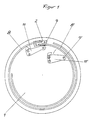
- a foot piece 2 is fastened in the edge region on the circular carrier board 1 shown in FIG. 1, retaining bolts fastened to the carrier board 1 4 protrude into corresponding holding holes in the foot piece 2.
- the foot piece 2 consists of a ring segment of rectangular cross section arranged concentrically to the center of the carrier plate and lies with its bottom surface 5 on the carrier plate 1.
- two holding slots 6 and 6 ′ are formed, which extend approximately parallel to one another with a different radius to the center of the carrier board 1.
- each holding slot 6 and 6 ' which is directed in the circumferential direction, is closed, while the other end opens out in the circumferential direction in such a way that the two mouths are directed in the opposite direction outwards.
- the holding slots 6 and 6 ' are continuous from the bottom surface 5 to the top 7 of the foot piece 2 and have an approximately rectangular cross section.
- each holding slot 6 and 6 ' is arranged at its one end an annular tonearm 8 and 8' formed from a hardened spring wire with a round cross section, the thickness of the tonearms 8 and 8 'corresponding to the width of the corresponding holding slots 6 and 6'.
- the two tonearms 8 and 8 ' are arranged in different planes, each parallel to the plane of the carrier board 1, in such a way that that of the carrier board 1 closer tonearm 8 is at a distance from the carrier board 1.
- both stop hammers 11 and 11' can be pivoted in parallel planes to the carrier board 1 about pivot axes 9 and 9 'on the carrier board 1 in the area near the foot piece on the respectively assigned tonearm 8 and 8 ' attacks.
- the tonearms 8 and 8 ' are each connected to the foot piece 2 by four welding spots 10 produced by laser welding.
- two welding spots 10 are formed on the side of the tonearms 8 and 8 ′ closer to the bottom surface 5 and two welding spots 10 on the upper side 7.
- the pitch is essentially determined by the vibration length of the tonearms 8 and 8 '.
- the desired pitch can be adjusted by forming a cross-sectional reduction, preferably in the area of the tonearms 8 and 8' directly protruding from the foot piece. This material can be removed either mechanically or using a laser.
Landscapes
- Physics & Mathematics (AREA)
- General Physics & Mathematics (AREA)
- Engineering & Computer Science (AREA)
- Acoustics & Sound (AREA)
- Multimedia (AREA)
- Laser Beam Processing (AREA)
- Percussion Or Vibration Massage (AREA)
Claims (9)
- Montre à répétition comprenant une platine de support (1) disposée dans une boîte de montre et sur laquelle peut être fixé un socle (2) d'un timbre, lequel timbre est un bras de timbre (8, 8') fixé par une extrémité au socle (2) et s'étendant librement à partir de celui-ci, contre lequel peut venir frapper un marteau de sonnerie (11, 11'), le socle (2) présentant un évidement de maintien dans lequel le bras de timbre (8, 8') pénètre et est fixé par une extrémité, caractérisée en ce que le bras de timbre (8, 8') est relié au socle (2) au moyen de plusieurs points de soudage (10) dont le matériau est de consistance dure.
- Montre à répétition selon la revendication 1, caractérisée en ce que les points de soudage (10) sont exécutés par soudage au laser.
- Montre à répétition selon une des revendications précédentes, caractérisée en ce que l'évidement de maintien est une fente de maintien (6, 6'), dont la largeur correspond à peu près à la largeur du bras de timbre (8, 8').
- Montre à répétition selon une des revendications précédentes, caractérisée en ce que le bras de timbre (8, 8') possède une section droite circulaire.
- Montre à répétition selon une des revendications précédentes, caractérisée en ce que le bras de timbre (8, 8') est fait d'un fil pour ressorts.
- Montre à répétition selon une des revendications précédentes, caractérisée en ce que le bras de timbre est fait d'un matériau trempé.
- Montre à répétition selon la revendication 3, caractérisée en ce que la hauteur de la fente de maintien (6, 6') est plus grande que la dimension en hauteur du bras de timbre (8, 8'), et le bras de timbre (8, 8') est disposé à distance de la platine de support (1) dans la fente de maintien (6, 6').
- Montre à répétition selon une des revendications précédentes, caractérisée en ce que le socle (2) présente plusieurs évidements de maintien juxtaposés et/ou superposés par rapport au plan de la platine de support (1) et dans chacun desquels est disposé un bras de timbre (8, 8').
- Montré à répétition selon une des revendications précédentes, caractérisée en ce que le bras de timbre (8, 8') possède une réduction de section dans sa zone faisant directement suite à la sortie du socle (2).
Applications Claiming Priority (2)
| Application Number | Priority Date | Filing Date | Title |
|---|---|---|---|
| DE4012059 | 1990-04-13 | ||
| DE4012059A DE4012059A1 (de) | 1990-04-13 | 1990-04-13 | Repetieruhr |
Publications (2)
| Publication Number | Publication Date |
|---|---|
| EP0451340A1 EP0451340A1 (fr) | 1991-10-16 |
| EP0451340B1 true EP0451340B1 (fr) | 1993-12-08 |
Family
ID=6404406
Family Applications (1)
| Application Number | Title | Priority Date | Filing Date |
|---|---|---|---|
| EP90122019A Expired - Lifetime EP0451340B1 (fr) | 1990-04-13 | 1990-11-17 | Montre à répétition |
Country Status (2)
| Country | Link |
|---|---|
| EP (1) | EP0451340B1 (fr) |
| DE (2) | DE4012059A1 (fr) |
Families Citing this family (8)
| Publication number | Priority date | Publication date | Assignee | Title |
|---|---|---|---|---|
| DE602006006678D1 (de) * | 2006-09-26 | 2009-06-18 | Montres Breguet Sa | Uhr mit Schlagwerk |
| JP5206233B2 (ja) * | 2007-09-05 | 2013-06-12 | セイコーエプソン株式会社 | 時計および携帯機器 |
| EP2048548B8 (fr) * | 2007-10-10 | 2022-02-16 | Richemont International S.A. | Mécanisme de sonnerie |
| CH702145A1 (fr) * | 2009-11-03 | 2011-05-13 | Montres Breguet Sa | Timbre pour une sonnerie d'une piece d'horlogerie. |
| CH709594B1 (fr) * | 2014-05-06 | 2021-09-30 | Blancpain Sa | Ensemble pour générer une sonnerie d'un mécanisme de sonnerie d'une montre. |
| EP3657268B1 (fr) * | 2018-11-22 | 2026-02-18 | Blancpain SA | Organe resonant pour un mecanisme de sonnerie d'une montre ou d'une boite a musique |
| EP3657267A1 (fr) * | 2018-11-22 | 2020-05-27 | Blancpain SA | Organe resonant pour un mecanisme de sonnerie d'une montre ou d'une boite a musique |
| EP3663869B1 (fr) * | 2018-12-06 | 2021-06-16 | Montres Breguet S.A. | Mecanisme de sonnerie d'horlogerie a marteau suspendu |
Family Cites Families (6)
| Publication number | Priority date | Publication date | Assignee | Title |
|---|---|---|---|---|
| CH26599A (de) * | 1902-08-09 | 1903-09-30 | Friedrich Mauthe | Gongfeder |
| CH55452A (de) * | 1912-02-12 | 1912-08-16 | Baptiste Viglino | Verfahren zur Herstellung von Glocken |
| US1704864A (en) * | 1924-12-31 | 1929-03-12 | Sessions Clock Co | Sounding mechanism for clocks |
| US1695087A (en) * | 1928-01-20 | 1928-12-11 | E Ingraham Co | Method of producing gong stands for clocks |
| CH344955A (fr) * | 1958-10-17 | 1960-02-29 | D Horlogerie Angelus Stolz Fre | Montre-bracelet à répétition |
| FR1492672A (fr) * | 1965-09-14 | 1967-08-18 | Suisse Pour L Ind Horlogere Sa | Procédé de fabrication d'une pièce d'horlogerie et pièce d'horlogerie obtenue par la mise en oeuvre de ce procédé |
-
1990
- 1990-04-13 DE DE4012059A patent/DE4012059A1/de not_active Withdrawn
- 1990-11-17 DE DE90122019T patent/DE59003804D1/de not_active Expired - Fee Related
- 1990-11-17 EP EP90122019A patent/EP0451340B1/fr not_active Expired - Lifetime
Also Published As
| Publication number | Publication date |
|---|---|
| DE4012059A1 (de) | 1991-10-17 |
| DE59003804D1 (de) | 1994-01-27 |
| EP0451340A1 (fr) | 1991-10-16 |
Similar Documents
| Publication | Publication Date | Title |
|---|---|---|
| DE10000728C2 (de) | Klammervorrichtung für Stangen | |
| DE2009379A1 (de) | Piezoelektrischer Oszillator in Form einer Stimmgabel fur zelthaltende Gerate | |
| EP0451340B1 (fr) | Montre à répétition | |
| DE2936887C2 (fr) | ||
| DE2645905C2 (de) | Befestigungsanordnung für Begrenzungstafeln in Form eines Gitters | |
| DD233084A5 (de) | Siebvorrichtung | |
| DE2616767A1 (de) | Mehrfach-bukkal-roehrchen | |
| DE69919189T2 (de) | Spielzeugbausatz | |
| DE60003962T2 (de) | Befestigung einer Spurplatte an einer Abzweigung | |
| DE19815289C1 (de) | Verfahren zum Zusammenbau einer Führungsschiene | |
| DE4305680A1 (de) | Gestellaufbau eines Tasteninstruments | |
| WO1995023668A1 (fr) | Procede et dispositif de soudage au moins de pieces metalliques | |
| DE69606157T2 (de) | Verdrehsicherrungsvorrichtung für elektrische Kabelschuh und Schweissverbindung für dieses Teil mit einem anderen Element | |
| DE2713983C2 (fr) | ||
| DE3917636C1 (fr) | ||
| DE19717710A1 (de) | Vorrichtung zum Befestigen eines Kopfzylinders | |
| DE2750365A1 (de) | Befestigung eines siebbodens | |
| DE2626708C3 (de) | Stabförmiger Schwingkristall | |
| DE19939323A1 (de) | Sägeblatt | |
| WO1985003363A1 (fr) | Horloge avec mecanisme de gong | |
| DE8906230U1 (de) | Vorrichtung zur Befestigung eines elektroakustischen Wandlers auf einer Leiterplatte | |
| DE9108822U1 (de) | Vorrichtung zur hängenden Halterung von Kabeln u.dgl. Langformteilen an Gebäudedecken | |
| DE3114657A1 (de) | Vorrichtung zur erzeugung von ultraschallwellen in einer fluessigkeitsmenge | |
| DE1523715B1 (de) | Einrichtung zum Schutz eines als Zeitnormal verwendeten mechanischen Schwingers gegen Stoesse und Erschuetterungen | |
| DE1659129C (de) | Betonbewehrung und damit versehener Balken |
Legal Events
| Date | Code | Title | Description |
|---|---|---|---|
| PUAI | Public reference made under article 153(3) epc to a published international application that has entered the european phase |
Free format text: ORIGINAL CODE: 0009012 |
|
| 17P | Request for examination filed |
Effective date: 19910711 |
|
| AK | Designated contracting states |
Kind code of ref document: A1 Designated state(s): CH DE FR IT LI |
|
| 17Q | First examination report despatched |
Effective date: 19921112 |
|
| GRAA | (expected) grant |
Free format text: ORIGINAL CODE: 0009210 |
|
| AK | Designated contracting states |
Kind code of ref document: B1 Designated state(s): CH DE FR IT LI |
|
| PG25 | Lapsed in a contracting state [announced via postgrant information from national office to epo] |
Ref country code: IT Free format text: LAPSE BECAUSE OF FAILURE TO SUBMIT A TRANSLATION OF THE DESCRIPTION OR TO PAY THE FEE WITHIN THE PRE;WARNING: LAPSES OF ITALIAN PATENTS WITH EFFECTIVE DATE BEFORE 2007 MAY HAVE OCCURRED AT ANY TIME BEFORE 2007. THE CORRECT EFFECTIVE DATE MAY BE DIFFERENT FROM THE ONE RECORDED.SCRIBED TIME-LIMIT Effective date: 19931208 |
|
| ET | Fr: translation filed | ||
| REF | Corresponds to: |
Ref document number: 59003804 Country of ref document: DE Date of ref document: 19940127 |
|
| PLBE | No opposition filed within time limit |
Free format text: ORIGINAL CODE: 0009261 |
|
| STAA | Information on the status of an ep patent application or granted ep patent |
Free format text: STATUS: NO OPPOSITION FILED WITHIN TIME LIMIT |
|
| 26N | No opposition filed | ||
| PG25 | Lapsed in a contracting state [announced via postgrant information from national office to epo] |
Ref country code: CH Effective date: 19941130 Ref country code: LI Effective date: 19941130 |
|
| PG25 | Lapsed in a contracting state [announced via postgrant information from national office to epo] |
Ref country code: FR Effective date: 19950731 |
|
| REG | Reference to a national code |
Ref country code: CH Ref legal event code: PL |
|
| PG25 | Lapsed in a contracting state [announced via postgrant information from national office to epo] |
Ref country code: DE Effective date: 19950801 |
|
| REG | Reference to a national code |
Ref country code: FR Ref legal event code: ST |