EP0451342B1 - Rundfunkempfänger mit zwei Empfangssystemen - Google Patents
Rundfunkempfänger mit zwei Empfangssystemen Download PDFInfo
- Publication number
- EP0451342B1 EP0451342B1 EP90122563A EP90122563A EP0451342B1 EP 0451342 B1 EP0451342 B1 EP 0451342B1 EP 90122563 A EP90122563 A EP 90122563A EP 90122563 A EP90122563 A EP 90122563A EP 0451342 B1 EP0451342 B1 EP 0451342B1
- Authority
- EP
- European Patent Office
- Prior art keywords
- signal
- receiver
- frequency
- local
- radio receiver
- Prior art date
- Legal status (The legal status is an assumption and is not a legal conclusion. Google has not performed a legal analysis and makes no representation as to the accuracy of the status listed.)
- Expired - Lifetime
Links
- 230000004044 response Effects 0.000 claims description 2
- 238000010586 diagram Methods 0.000 description 6
- 230000005236 sound signal Effects 0.000 description 2
- 238000007796 conventional method Methods 0.000 description 1
- 230000005684 electric field Effects 0.000 description 1
- 230000006870 function Effects 0.000 description 1
- 238000004519 manufacturing process Methods 0.000 description 1
Images

Classifications
-
- H—ELECTRICITY
- H04—ELECTRIC COMMUNICATION TECHNIQUE
- H04B—TRANSMISSION
- H04B1/00—Details of transmission systems, not covered by a single one of groups H04B3/00 - H04B13/00; Details of transmission systems not characterised by the medium used for transmission
- H04B1/06—Receivers
- H04B1/16—Circuits
- H04B1/1646—Circuits adapted for the reception of stereophonic signals
-
- H—ELECTRICITY
- H04—ELECTRIC COMMUNICATION TECHNIQUE
- H04B—TRANSMISSION
- H04B7/00—Radio transmission systems, i.e. using radiation field
- H04B7/02—Diversity systems; Multi-antenna system, i.e. transmission or reception using multiple antennas
- H04B7/12—Frequency diversity
Definitions
- the present invention relates to a radio receiver of the twin tuner type which has two parallel receiving systems.
- RDS radio data system
- frequency data (AF) of a broadcasting station broadcasting a program is contained in the RDS data.
- AF stands for Alternative Frequencies and relates to data for indicating the frequencies of stations broadcasting the same program in circumferential areas.
- a receiver writes the data of the necessary AF list into a memory installed therein.
- the AF data is read out of the memory and signal levels of the AF frequencies are checked by a conventional method, i.e., detecting the strength of the electric field.
- the receiver checks signal levels of the AF frequencies, and selects a broadcasting frequency that can be received with better receive quality than the present one, and uses that frequency for receiving the program.
- muting is applied to a broadcasting station that is presently subjected to the audio monitor, for a short time. During this muting period, the receiver searches another broadcasting station in the same network. If a radio wave with respect to a new broadcasting station as searched can be received with better receive quality, the receiver uses the radio wave of the new station for receiving the program.
- This type of radio receiver is operable in such a way that a first tuner is used for the audio monitor, while a second tuner is used for searching the best channel.
- a receive quality in the first tuner is better than that in the second tuner, the receiver is instantaneously switched to the channel of the highest receiving quality.
- the receiver can get the service of the same network without the unnatural feelings provided to listeners based on the temporary muting periods described above.
- a superheterodyne system is employed for these types of receivers.
- a high local frequency for example, is used for a local signal, generated by a local oscillator
- a local signal of the first receiver whose frequency is the receiving frequency plus 10.7 MHz, may fall within the frequency band of the received RF signal of the second receiver.
- the reverse case may exist i.e., a local signal of the second receiver falls within the frequency band of a received RF signal of the first receiver. This results in negatively affecting the receiving band of the other receiver.
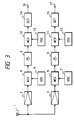
- Fig. 3 is a block diagram showing a basic arrangement of a twin tuner of a double superheterodyne system.
- An RF signal received by an antenna 1 is properly amplified by RF amplifiers 2 and 3, and then applied to mixers 4 and 5.
- the mixers receive respectively local signals from local oscillators 6 and 7, and produce first intermediate frequency (IF) signals.
- the produced signals are amplified by IF signal amplifiers 8 and 9, and then applied to mixers 10 and 11, respectively.
- the mixers 10 and 11 which now receive the amplified IF signals, receive local signals from local oscillators 12 and 13, and convert the first IF signals into second IF signals, respectively.
- the second IF frequency signals are demodulated by detector circuits 14 and 15, and output from output terminals 16 and 17, respectively.
- an oscillating frequency of each local oscillator 6 and 7 is selected to be at least about, for example, 20 MHz, higher than the frequency of the received RF signal.
- the first IF signal as produced using the first local signal is mixed with a second local signal generated by local oscillators 12 and 13 to thereby form an IF signal of 10.7 MHz.
- the frequency of the local signal will never fall within the frequency band of the received RF signal.
- the local signal of the first receiver negatively affects the received RF frequency band of the second receiver.
- the double superheterodyne system must be employed for both of the receivers.
- the receiver using the two double superheterodyne receiving systems needs additionally the mixers 10 and 11 and the local oscillators 12 and 13. This leads to an increase in manufacturing costs and makes the circuit arrangement complicated.
- the present invention has an object to provide a radio receiver which is free from the increased cost and complicated circuit arrangement discussed above.
- the radio receiver is arranged such that a single receiving frequency band is divided into at least two frequency ranges, a first frequency range and a second frequency range, and a demodulated output signal of the first receiver or that of the second receiver is selected according to the first and second frequency ranges.
- the first local signal in the first receiver will never enter into the frequency band of the received signal in the second receiver.
- the local signal in the second receiver will never enter into the frequency band of the received signal in the first receiver.
- the problem of the local signal of one receiver negatively affecting the received RF frequency band of another receiver is successfully solved.
- Fig. 1 is a block diagram showing an embodiment of a radio receiver according to the present invention.
- reference numeral 20 designates an antenna.
- An RF signal derived from the antenna 20 is applied to an RF amplifier 21 in a first receiving system or receiver of the double superheterodyne type.
- the RF signal is amplified by the amplifier 21 and then applied to a mixer 22.
- the mixer 22 is coupled with a local oscillator 23.
- the RF signal is mixed with a local signal generated by the local oscillator 23, and converted into a first intermediate frequency signal.
- the first IF signal is amplified by an IF amplifier 24, and then applied to a mixer 25.
- the mixer 25 is coupled with a local oscillator 26.
- the first IF signal is mixed with a local signal generated by the local oscillator 26, and converted into a second intermediate frequency signal.
- the second IF signal is selectively amplified by an IF amplifier 27, and then applied to a detector circuit 28. Then, it is demodulated by the detector circuit 28, and applied to a selector 29.
- the RF signal derived from the antenna 20 is applied to an RF amplifier 30 in a second receiving system or receiver of the single superheterodyne type.
- the RF signal is amplified by the amplifier 30 and then applied to a mixer 31.
- the mixer 31 is coupled with a local oscillator 32.
- the RF signal is mixed with a local signal as generated by the local oscillator 32, and converted into an IF signal.
- This IF signal is amplified by an IF amplifier 33, and then applied to a detector circuit 34. Then, it is demodulated by the detector circuit 34, and applied to the selector 29.
- the selector 29 selects the demodulated signal of the first receiver or that of the second receiver.
- the demodulated audio signal as selected is applied to an output terminal 35.
- the non-selected audio signal is applied to a central processing unit (CPU 36) along line 40 as a demodulation control signal.
- the CPU 36 fetches frequency data (AF) of a broadcasting station which broadcasts a program as one of the services performed by the RDS broadcasting system as described above.
- AF frequency data
- the CPU 36 is coupled with a keyboard 37 for entering instructions, such as a channel selection.
- the CPU 36 produces local signal control signals along lines 41 and 42 which are to be applied, respectively, to the local oscillators 32 and 23 of the first and second receivers, respectively.
- the receiving frequency band is an FM band of 87.50 to 108.00 MHz
- the frequency of the local signal generated by the local oscillator 23 ranges from 108.90 to 129.40 MHz, in the first receiver of the double superheterodyne type. Then, the frequency of the first IF signal is 21.4 MHz.
- the first IF signal of 21.40 MHz is mixed with the local signal of frequency 32.1 MHz from the local oscillator 26, and converted into an IF signal of 10.7 MHz, which in turn is demodulated by the detector circuit 28.
- the frequency of the local signal as generated by the local oscillator 32 is set between 98.20 MHz and 118.70 MHz.
- the frequency of the resultant IF signal is 10.70 MHz.
- the IF signal is demodulated by the detector circuit 34.
- the received frequency band is divided into at least two frequency bands, a first frequency band and a second frequency band.
- the first and second receivers receive and demodulate the signals within the first and second frequency bands, respectively.
- the FM receiving frequency band is between 87.50 MHz and 108.00 MHz as mentioned above, it is divided into a low frequency band of 87.50 to 97.75 MHz and a high frequency band of 97.80 to 108.00 MHz.
- the selector 29 selects the demodulated signal of the first receiver (double superheterodyne receiver) or that of the second receiver (single superheterodyne receiver) to be output onto terminal 35 according to the receiving frequency of the main tuner.
- the first receiver is used for the main tuner, and the second receiver, for the sub tuner.
- the second receiver is used for the main tuner, and the first receiver, for the sub tuner.
- the CPU 36 controls the selector 29 along line 43 in such a way that when the receiving frequency falls within the low frequency band, as indicated to the CPU 36 by the keyboard 37, the movable contacts of the selector 29 are turned to the fixed contacts shown in Fig. 1, and when it falls within the high frequency band, the selector is turned to the other fixed contacts.
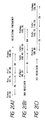
- Figs. 2(A) through 2(C) are diagrams showing the operations as mentioned above.
- Fig. 2(A) shows a receiving frequency band of the radio receiver. As shown, the low frequency band ranges from Frmin (87.50 MHz) to Frc (97.75 MHz), and the high frequency band ranges from Frc' (97.80 MHz) to Frmax (108.00 MHz).
- the low frequency band of the local signal ranges from Fo2min (98.20 MHz) to Fo2c (108.45 MHz), and the high frequency band ranges from Fo2c' (108.50 MHz) to Fo2max (118.7 MHz).
- the low frequency band of the local signal ranges from Folmin (108.90 MHz) to Folc (119.15 MHz), and the high frequency band ranges from Folc' (119.20 MHz) to Folmax (129.40 MHz).
- the first receiver is used as the main tuner, and the frequency of the local signal is within the range of CL in Fig. 2(C).
- the second receiver is used as the sub tuner, the frequency of the local signal is within the range of BL in Fig. 2(B). Accordingly, neither the local signal of the first receiver nor that of the second receiver will be coincident with the receiving frequency in the low frequency band, and hence the local signals will not negatively affect the received RF signal.
- the second receiver To receive a signal within the high frequency band (AH in Fig. 2(A)), the second receiver is used as the main tuner, and the frequency of the local signal is within the range of BH in Fig. 2(B).
- the frequency of the local signal is within the range of CH in Fig. 2(C). Accordingly, neither the local signal of the first receiver nor that of the second receiver will be coincident with the receive frequency in the high frequency band, and hence the local signals will not negatively affect the received RF signal.
- the radio receiver of the invention is arranged such that a single receiving frequency band is divided into at least two frequency ranges, a first frequency range and a second frequency range, and a demodulated output signal of the first receiver or that of the second receiver is selected according to whether the received signal is of the first or the second frequency ranges.
- the first local signal will never enter into the frequency band of the received signal of the second receiver.
- the second local signal will, correspondingly, never enter into the frequency band of the received signal of the first receiver.
- the problem of the local signal of one receiver negatively affecting the received RF signal of another receiver is successfully solved.
- one of the receivers is of the double superheterodyne type, and the other is of the single superheterodyne type.
- the radio receiver of the invention is lower in cost and simpler in circuit arrangement than the conventional radio receiver in which both the receivers must be of the double superheterodyne type.
- the network follower using the AF data containing in the RDS data is used as an example. It is evident, however, that the present invention is applicable for another type of radio receiver with a function to monitor the quality and content of the broadcasting wave.
Landscapes
- Engineering & Computer Science (AREA)
- Computer Networks & Wireless Communication (AREA)
- Signal Processing (AREA)
- Circuits Of Receivers In General (AREA)
- Superheterodyne Receivers (AREA)
Claims (5)
- Funkempfangsgerät, umfassend:einen ersten Doppelüberlagerungsempfänger mit einem ersten Mischer (22) zum Anlegen eines ersten lokalen Signals an ein empfangenes Hochfrequenzsignal, um so ein erstes Zwischenfrequenzsignal auszugeben, einen zweiten Mischer (25) zum Anlegen eines zweiten lokalen Signals an das genannte erste Zwischenfrequenzsignal, um ein zweites Zwischenfrequenzsignal auszugeben und eine erste Erfassungsschaltung (28) zum Demodulieren des zweiten Zwischenfrequenzsignals;einen zweiten Einfachüberlagerungsempfanger mit einem dritten Mischer (31) zum Anlegen eines dritten lokalen Signals an das empfangene Hochfrequenzsignal, um so ein drittes Zwischenfrequenzsignal auszugeben, und eine zweite Erfassungschaltung (34) zum Demodulieren des dritten Zwischenfrequenzsignals,wobei ein einzelnes Empfangsfrequenzband in einen ersten Frequenzbereich (AL) und einen zweiten Frequenzbereich (AH) unterteilt ist,eine Auswahleinrichtung (29) zum Auswählen eines der demodulierten Ausgangssignale des ersten und zweiten Empfängers als ein Ausgangssignal, abhängig davon, ob des empfangene Hochfrequenzsignal sich im ersten oder zweiten Bereich befindet und zum Bestimmen des anderen demodulierten Ausgangssignals als ein nicht ausgewähltes Signal, welches als ein Demodulationssteuersignal verwendet wird.
- Funkempfangsgerät nach Anspruch 1, worin die Auswahleinrichtung (29) eine Schalteinrichtung umfaßt zum Umschalten zwischen den Ausgangssignalen des ersten und zweiten Empfängers im Ansprechen auf ein Steuersignal einer Steuereinrichtung (36).
- Funkempfangsgerät nach Anspruch 2, worin die Steuereinrichtung (36) eine CPU umfaßt, welche ein Eingangssignal von einer Tastatur (37) empfängt, welches einer gewünschten Frequenz des Hochfrequenzsignals entspricht.
- Funkempfangsgerät nach einem der Ansprüche 1 bis 3, worin das Gerät ein Netzwerkfolgesystem ist.
- Funkempfangsgerät nach Anspruch 3, worin das nicht ausgewählte Signal an die Steuereinrichtung (36) angelegt wird, um einen Netzwerkfolgebetrieb auszuführen.
Applications Claiming Priority (2)
| Application Number | Priority Date | Filing Date | Title |
|---|---|---|---|
| JP2095186A JPH03293824A (ja) | 1990-04-12 | 1990-04-12 | ラジオ受信機 |
| JP95186/90 | 1990-04-12 |
Publications (3)
| Publication Number | Publication Date |
|---|---|
| EP0451342A2 EP0451342A2 (de) | 1991-10-16 |
| EP0451342A3 EP0451342A3 (en) | 1993-02-10 |
| EP0451342B1 true EP0451342B1 (de) | 1996-01-31 |
Family
ID=14130723
Family Applications (1)
| Application Number | Title | Priority Date | Filing Date |
|---|---|---|---|
| EP90122563A Expired - Lifetime EP0451342B1 (de) | 1990-04-12 | 1990-11-26 | Rundfunkempfänger mit zwei Empfangssystemen |
Country Status (4)
| Country | Link |
|---|---|
| US (1) | US5239697A (de) |
| EP (1) | EP0451342B1 (de) |
| JP (1) | JPH03293824A (de) |
| DE (1) | DE69025172T2 (de) |
Families Citing this family (21)
| Publication number | Priority date | Publication date | Assignee | Title |
|---|---|---|---|---|
| US5392330A (en) * | 1992-01-08 | 1995-02-21 | Thomson Consumer Electronics, Inc. | Offset down conversion for a two-handset cordless telephone system |
| DE4236621A1 (de) * | 1992-10-29 | 1994-05-05 | Becker Autoradio | Verfahren zur Abstimmung eines Rundfunkempfängers |
| JP3565281B2 (ja) * | 1993-10-08 | 2004-09-15 | ソニー株式会社 | 受信機 |
| JPH07246915A (ja) * | 1994-03-10 | 1995-09-26 | Alpine Electron Inc | 車載用受信装置 |
| US5812591A (en) * | 1994-09-23 | 1998-09-22 | Garmin Corporation | Dual conversion GPS frequency converter and frequency plan for same |
| US5758266A (en) * | 1994-09-30 | 1998-05-26 | Qualcomm Incorporated | Multiple frequency communication device |
| US5550832A (en) * | 1994-12-12 | 1996-08-27 | Digital Call Alert | Time division multiple access radio transmission activated receiver switch |
| JPH09275358A (ja) * | 1996-04-08 | 1997-10-21 | Matsushita Electric Ind Co Ltd | 複数帯域移動無線装置 |
| JP3690889B2 (ja) * | 1996-06-10 | 2005-08-31 | 松下電器産業株式会社 | 受信回路 |
| FI102432B (fi) * | 1996-09-11 | 1998-11-30 | Filtronic Lk Oy | Kaksitoimisen radioviestimen antennisuodatusjärjestely |
| JP3702551B2 (ja) * | 1996-09-13 | 2005-10-05 | 住友電装株式会社 | 放送受信システム及びこれを利用した放送受信方法 |
| JP3226807B2 (ja) * | 1996-11-20 | 2001-11-05 | 静岡日本電気株式会社 | 無線呼出システム用の自動周波数補正装置および自動周波数補正方法 |
| WO1998044750A2 (de) * | 1997-03-27 | 1998-10-08 | Siemens Aktiengesellschaft | Verfahren und anordnung zur übertragung von daten |
| US6442382B1 (en) * | 1997-06-27 | 2002-08-27 | Agere Systems Guardian Corp. | Filter switching system and method |
| US6272191B1 (en) | 1997-09-09 | 2001-08-07 | Sumitomo Wiring Systems, Ltd. | Information receiving system and an information receiving method using such a system |
| TW456148B (en) | 1998-06-16 | 2001-09-21 | United Video Properties Inc | Interactive television program guide with simultaneous watch and record capabilities |
| US6760579B1 (en) * | 1998-11-27 | 2004-07-06 | Fujitsu Ten Limited | Receiving system having a plurality of frequency converters for use with a vehicle |
| US7127010B1 (en) * | 1999-07-29 | 2006-10-24 | Bose Corporation | Oscillator controlling |
| US7908080B2 (en) | 2004-12-31 | 2011-03-15 | Google Inc. | Transportation routing |
| US20100261500A1 (en) * | 2009-04-09 | 2010-10-14 | Broadcom Corporation | Multiple frequency band multiple standard information signal modular baseband processing module |
| US20120223810A1 (en) * | 2011-03-04 | 2012-09-06 | GM Global Technology Operations LLC | System and method for extending remote vehicle control functions |
Family Cites Families (16)
| Publication number | Priority date | Publication date | Assignee | Title |
|---|---|---|---|---|
| JPS53105107A (en) * | 1977-02-24 | 1978-09-13 | Sony Corp | Receiver |
| JPS56125122A (en) * | 1980-03-07 | 1981-10-01 | Radio Res Lab | Diversity reception system |
| US4317218A (en) * | 1980-03-26 | 1982-02-23 | General Electric Company | Arrangement for remote control of repeater stations |
| JPS5797732A (en) * | 1980-12-10 | 1982-06-17 | Sanyo Electric Co Ltd | Radio receiver |
| US4521916A (en) * | 1983-11-29 | 1985-06-04 | Rca Corporation | Frequency synthesis tuning control system for a double-conversion tuner |
| US4598425A (en) * | 1984-02-09 | 1986-07-01 | Zenith Electronics Corporation | All-channel television tuning system |
| DE3416917A1 (de) * | 1984-05-08 | 1985-11-14 | Blaupunkt-Werke Gmbh, 3200 Hildesheim | Autoempfaenger mit einem verkehrsfunkdecoder und einer sendersuchlaufeinrichtung |
| JPS6165536A (ja) * | 1984-09-06 | 1986-04-04 | Sony Corp | シンセサイザ方式fm−am受信機 |
| JPS6178230A (ja) * | 1984-09-26 | 1986-04-21 | Nec Corp | 集積化am/fm切換回路 |
| JPS61284125A (ja) * | 1985-06-11 | 1986-12-15 | Nec Corp | ダイバ−シチ受信方式 |
| JPS61290813A (ja) * | 1985-06-18 | 1986-12-20 | Pioneer Electronic Corp | Fm受信機 |
| JPS63152231A (ja) * | 1986-12-16 | 1988-06-24 | Sharp Corp | Rfコンバ−タ回路 |
| JPH0744485B2 (ja) * | 1987-05-22 | 1995-05-15 | 三菱電機株式会社 | 自動車電話装置 |
| JP2622972B2 (ja) * | 1987-09-17 | 1997-06-25 | 三洋電機株式会社 | Fmラジオ受信機 |
| JPH0243822A (ja) * | 1988-08-03 | 1990-02-14 | Toshiba Corp | テレビジョンチューナ |
| JP2757399B2 (ja) * | 1988-11-30 | 1998-05-25 | ソニー株式会社 | 受信機 |
-
1990
- 1990-04-12 JP JP2095186A patent/JPH03293824A/ja active Pending
- 1990-11-21 US US07/616,959 patent/US5239697A/en not_active Expired - Fee Related
- 1990-11-26 EP EP90122563A patent/EP0451342B1/de not_active Expired - Lifetime
- 1990-11-26 DE DE69025172T patent/DE69025172T2/de not_active Expired - Fee Related
Also Published As
| Publication number | Publication date |
|---|---|
| EP0451342A2 (de) | 1991-10-16 |
| EP0451342A3 (en) | 1993-02-10 |
| DE69025172D1 (de) | 1996-03-14 |
| US5239697A (en) | 1993-08-24 |
| DE69025172T2 (de) | 1996-05-30 |
| JPH03293824A (ja) | 1991-12-25 |
Similar Documents
| Publication | Publication Date | Title |
|---|---|---|
| US5239697A (en) | Radio receiver with two receiving systems | |
| EP0602438B1 (de) | RDS-Rundfunkempfänger | |
| US4352208A (en) | Automatic IF selectivity for radio receiver system | |
| EP0346495B1 (de) | Fernsehkanalschalter | |
| JPH05227046A (ja) | 複数のアンテナを備えた超短波受信機 | |
| MY110935A (en) | Using a first if of 43.5 mhz or less in an fm radio in a television tuner. | |
| MY106076A (en) | Stereo fm radio in a television receiver | |
| US6628930B1 (en) | Radio receiver with two tuners and a switch for verifying reception quality at an alternative frequency | |
| MY107888A (en) | Fm trap for a television tuner permitting both tv and fm reception through the same tuner. | |
| EP0668656B1 (de) | Tuner für Satelliten-Rundfunkempfänger | |
| US7099644B2 (en) | Beamsteering control system for a vehicle radio receiver | |
| MY107630A (en) | Mono fm radio in a television receiver. | |
| JP4151917B2 (ja) | 移動体用受信機 | |
| JP2000138566A (ja) | 放送受信装置 | |
| JP3254377B2 (ja) | 受信装置 | |
| JPH03263911A (ja) | 移動体用ラジオ受信機 | |
| JPH044616A (ja) | ラジオ受信機 | |
| EP0510914B1 (de) | RDS-Empfänger | |
| KR970007477B1 (ko) | 방송수신기의 자동 채널 선국 기억 방법 | |
| JP2001016150A (ja) | 多重放送受信装置 | |
| JPS631172A (ja) | オ−デイオ信号受信機 | |
| JPS647695B2 (de) | ||
| JPH08316862A (ja) | ラジオ受信機 | |
| JPH04167610A (ja) | 受信機 | |
| JPS5864818A (ja) | 受信機 |
Legal Events
| Date | Code | Title | Description |
|---|---|---|---|
| PUAI | Public reference made under article 153(3) epc to a published international application that has entered the european phase |
Free format text: ORIGINAL CODE: 0009012 |
|
| AK | Designated contracting states |
Kind code of ref document: A2 Designated state(s): DE FR |
|
| PUAL | Search report despatched |
Free format text: ORIGINAL CODE: 0009013 |
|
| AK | Designated contracting states |
Kind code of ref document: A3 Designated state(s): DE FR |
|
| 17P | Request for examination filed |
Effective date: 19930518 |
|
| 17Q | First examination report despatched |
Effective date: 19940520 |
|
| GRAA | (expected) grant |
Free format text: ORIGINAL CODE: 0009210 |
|
| AK | Designated contracting states |
Kind code of ref document: B1 Designated state(s): DE FR |
|
| PG25 | Lapsed in a contracting state [announced via postgrant information from national office to epo] |
Ref country code: FR Effective date: 19960131 |
|
| REF | Corresponds to: |
Ref document number: 69025172 Country of ref document: DE Date of ref document: 19960314 |
|
| EN | Fr: translation not filed | ||
| PLBE | No opposition filed within time limit |
Free format text: ORIGINAL CODE: 0009261 |
|
| STAA | Information on the status of an ep patent application or granted ep patent |
Free format text: STATUS: NO OPPOSITION FILED WITHIN TIME LIMIT |
|
| PGFP | Annual fee paid to national office [announced via postgrant information from national office to epo] |
Ref country code: DE Payment date: 19961230 Year of fee payment: 7 |
|
| 26N | No opposition filed | ||
| PG25 | Lapsed in a contracting state [announced via postgrant information from national office to epo] |
Ref country code: DE Free format text: LAPSE BECAUSE OF NON-PAYMENT OF DUE FEES Effective date: 19980801 |