EP0451366B1 - Sauganschlussverbindung für eine Hydropumpe - Google Patents
Sauganschlussverbindung für eine Hydropumpe Download PDFInfo
- Publication number
- EP0451366B1 EP0451366B1 EP90125345A EP90125345A EP0451366B1 EP 0451366 B1 EP0451366 B1 EP 0451366B1 EP 90125345 A EP90125345 A EP 90125345A EP 90125345 A EP90125345 A EP 90125345A EP 0451366 B1 EP0451366 B1 EP 0451366B1
- Authority
- EP
- European Patent Office
- Prior art keywords
- suction
- bore
- pump
- hose nipple
- connecting bore
- Prior art date
- Legal status (The legal status is an assumption and is not a legal conclusion. Google has not performed a legal analysis and makes no representation as to the accuracy of the status listed.)
- Expired - Lifetime
Links
- 239000007788 liquid Substances 0.000 title description 2
- 210000002445 nipple Anatomy 0.000 claims description 37
- 238000006073 displacement reaction Methods 0.000 claims description 4
- 238000007789 sealing Methods 0.000 claims description 4
- 239000012530 fluid Substances 0.000 description 7
- 230000006835 compression Effects 0.000 description 2
- 238000007906 compression Methods 0.000 description 2
- 238000011161 development Methods 0.000 description 2
- 230000018109 developmental process Effects 0.000 description 2
- 238000004519 manufacturing process Methods 0.000 description 2
- 230000001419 dependent effect Effects 0.000 description 1
- 238000005553 drilling Methods 0.000 description 1
- 238000000926 separation method Methods 0.000 description 1
- 238000009423 ventilation Methods 0.000 description 1
Images
Classifications
-
- F—MECHANICAL ENGINEERING; LIGHTING; HEATING; WEAPONS; BLASTING
- F04—POSITIVE - DISPLACEMENT MACHINES FOR LIQUIDS; PUMPS FOR LIQUIDS OR ELASTIC FLUIDS
- F04C—ROTARY-PISTON, OR OSCILLATING-PISTON, POSITIVE-DISPLACEMENT MACHINES FOR LIQUIDS; ROTARY-PISTON, OR OSCILLATING-PISTON, POSITIVE-DISPLACEMENT PUMPS
- F04C14/00—Control of, monitoring of, or safety arrangements for, machines, pumps or pumping installations
- F04C14/24—Control of, monitoring of, or safety arrangements for, machines, pumps or pumping installations characterised by using valves controlling pressure or flow rate, e.g. discharge valves or unloading valves
- F04C14/26—Control of, monitoring of, or safety arrangements for, machines, pumps or pumping installations characterised by using valves controlling pressure or flow rate, e.g. discharge valves or unloading valves using bypass channels
-
- B—PERFORMING OPERATIONS; TRANSPORTING
- B60—VEHICLES IN GENERAL
- B60T—VEHICLE BRAKE CONTROL SYSTEMS OR PARTS THEREOF; BRAKE CONTROL SYSTEMS OR PARTS THEREOF, IN GENERAL; ARRANGEMENT OF BRAKING ELEMENTS ON VEHICLES IN GENERAL; PORTABLE DEVICES FOR PREVENTING UNWANTED MOVEMENT OF VEHICLES; VEHICLE MODIFICATIONS TO FACILITATE COOLING OF BRAKES
- B60T8/00—Arrangements for adjusting wheel-braking force to meet varying vehicular or ground-surface conditions, e.g. limiting or varying distribution of braking force
- B60T8/32—Arrangements for adjusting wheel-braking force to meet varying vehicular or ground-surface conditions, e.g. limiting or varying distribution of braking force responsive to a speed condition, e.g. acceleration or deceleration
- B60T8/34—Arrangements for adjusting wheel-braking force to meet varying vehicular or ground-surface conditions, e.g. limiting or varying distribution of braking force responsive to a speed condition, e.g. acceleration or deceleration having a fluid pressure regulator responsive to a speed condition
- B60T8/40—Arrangements for adjusting wheel-braking force to meet varying vehicular or ground-surface conditions, e.g. limiting or varying distribution of braking force responsive to a speed condition, e.g. acceleration or deceleration having a fluid pressure regulator responsive to a speed condition comprising an additional fluid circuit including fluid pressurising means for modifying the pressure of the braking fluid, e.g. including wheel driven pumps for detecting a speed condition, or pumps which are controlled by means independent of the braking system
- B60T8/4031—Pump units characterised by their construction or mounting
Definitions
- the invention relates to a suction connection for a self-priming hydraulic pump, in particular a circulation or stroke displacement pump for hydraulic vehicle brake systems, according to the type of the main claim.
- a pump with a suction-side connector for fastening a hose or pipe is known.
- the connector is screwed into a housing part and serves to hold down a spring and to guide a jet pipe in a chamber of the pump housing.
- the jet pipe forms a pressure-dependent actuated seat valve in a duct connection between the pressure side and the suction side of the pump.
- the connector is not intended to be removed from the pump housing to release the hose or tube. It is also not intended to remove the jet pipe from the chamber and to release the connection between the pressure side and the suction side of the pump.
- the suction connection according to the invention with the characterizing features of the main claim has the advantage that the suction of air in the absence of a suction line without moving components of the pump is reliably avoided because the suction hose nipple removed from the connection bore releases a short-circuit connection between the pressure side and the suction side of the pump, due to which a build-up of pressure with the delivery of air on the pump pressure side is excluded.
- the measure characterized in claim 2 is advantageous because the connecting hole can be produced with little effort, preferably in a single drilling operation together with the connection hole for the pressure line.
- the embodiment specified in claim 3 has the advantage that the suction hose nipple can be produced inexpensively with the pin as a turned part.
- the embodiment disclosed in claim 5 is advantageous because simple securing of the suction hose nipple and deriving hydraulic pressure forces acting on the nipple and tensile forces acting on the suction hose are achieved.
- a pressure relief valve which can be produced in connection with the production of the suction hose nipple and is integrated in this is achieved, which, in contrast to the otherwise conventional arrangement of such a valve in the pump housing, is inexpensive with regard to production, assembly and testing.
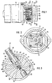
- FIG. 1 shows a view of a self-priming hydraulic pump with a partially broken open pump housing
- FIG. 2 shows a cross section through the pump housing along the line II-II in FIG. 1 on a different scale with a representation of the suction chamber and the pressure chamber of the pump
- FIG the pump housing part along the line III-III in Figure 1 also on a different scale with a suction hose nipple accommodated in the pump housing, which blocks a connection bore between the suction chamber and the pressure chamber of the pump with a pin.
- the self-priming hydraulic pump 10 shown in FIG. 1 has a pump housing 11 in which a gear pump 12 with internal teeth is arranged.
- the gear pump 12 belonging to the genus of the circulation displacement pumps can be driven by an electric drive motor 13 flanged to the pump housing 11.
- An inner housing 16 of the gear pump 12 is arranged in the pump housing 11, in which a toothed outer rotor 17 and a toothed inner rotor 18 are accommodated.
- the inner housing 16 includes a kidney-shaped suction chamber 19 and a kidney-shaped pressure chamber 20 of the gear pump 12 (FIG. 2).
- a suction bore 24 leads from the suction space 19 of the gear pump 12 to a connection bore 25 of the pump housing 11 for receiving a suction hose nipple 26 of a suction line 27 for the operating fluid to be delivered by the hydraulic pump 10 (FIG. 3).
- a pressure line 30 leads to a connecting bore 31 in the pump housing 11.
- the connecting bore 31 serves as a channel between the connection bore 25 for the suction hose nipple 26 of the suction line and a connection bore 32 of the pump housing 11 for a pressure line, not shown.
- the connection bore 25, the connection bore 31 and the connection bore 32 run with the same longitudinal axis. In a departure from the exemplary embodiment shown, they can be arranged in a connection plate which rests against the pump housing 11 at the end.
- connection bore 25 for the suction hose nipple 26 is smooth on the circumference and extends at an angle of approximately 60 ° to the horizontal plane essentially above the longitudinal axis of the hydraulic pump 10.
- the mouth 36 of the connection bore 25 is therefore above the suction chamber 19 and the pressure chamber 20 of the gear pump 12 .
- connection bore 31 extending from the bottom of the connection bore 25 for the suction hose nipple 26 has a smaller diameter than the connection bore.
- the connection bore 31 is axially limited by the connection bore 32 for the pressure line lying below the horizontal plane of the hydraulic pump 10.
- the pressure line 30 coming from the pressure chamber 20 of the gear pump 12 opens into the section of the connecting hole 31 assigned to the connection bore 32 for the pressure line.
- the suction hose nipple 26 has, adjacent to its nozzle 40, a cylindrical section 41 which fits in the connection bore 25 of the pump housing 11.
- the section 41 of the suction hose nipple 26 is sealed against the pump housing 11 by a sealing ring 42 arranged on the circumference.
- an annular groove 43 is formed, in which a spring pin 44, driven from the free end face of the pump housing 11, engages. This serves as a safety pin against unintentional pulling out of the suction hose nipple 26 from the connection bore 25.
- the spring pin 44 absorbs hydraulic forces acting on the suction hose nipple 26.
- the suction hose nipple 26 is continued in a section 45 of reduced diameter.
- the grommet 40, the larger-diameter section 41 and the smaller-diameter section 45 of the suction hose nipple 26 are traversed by a longitudinal bore 46 that runs coaxially. This is crossed in section 45 of the suction hose nipple 26 by a transverse bore 47, so that there is a liquid-conducting connection from the inside of the suction line 27 into the section 48 of the connecting bore 25 which is not completely filled by the section 45 of the suction hose nipple 26.
- the section 48 of the connection bore 25 extends from the suction bore 24 leading into the suction chamber 19 of the gear pump 12.
- the suction hose nipple 26 has a coaxial cylindrical pin 52 which fits into the connecting bore 31 to the mouth of the pressure line 30.
- a sealing ring 53 is received on the circumferential side for the sealed closure of the connecting bore 31.
- the pin 52 is inserted as a separate component in the longitudinal bore 46 of the suction hose nipple 26 and welded to the section 45 thereof.
- the pin 52 has a coaxial with the longitudinal bore 46 running, continuous overflow bore 54, which forms a valve seat 55 at its mouth near the transverse bore 47, on the suction chamber side, for a ball 56 movably arranged in the longitudinal bore 46 and acting as a valve closing member.
- valve seat 55 acts on the valve seat 55 under the action of a compression spring 57 arranged in the longitudinal bore 46 and supported on the suction hose nipple 26.
- the valve seat 55, the ball 56 and the compression spring 57 form a pressure relief valve 58 arranged between the pressure side and the suction side of the gear pump 12.
- the pin 52 can have a bore without a bore, in contrast to the exemplary embodiment described formed and integrally formed on the suction hose nipple 26.
- the invention can also be used with other hydraulic circulation or stroke displacement pumps, insofar as these are self-priming.
Landscapes
- Engineering & Computer Science (AREA)
- Physics & Mathematics (AREA)
- Fluid Mechanics (AREA)
- Mechanical Engineering (AREA)
- Transportation (AREA)
- General Engineering & Computer Science (AREA)
- Valves And Accessory Devices For Braking Systems (AREA)
- Details And Applications Of Rotary Liquid Pumps (AREA)
- Details Of Reciprocating Pumps (AREA)
- Rotary Pumps (AREA)
Description
- Die Erfindung geht aus von einer Sauganschlußverbindung für eine selbstansaugende Hydropumpe, insbesondere Umlauf- oder Hubverdrängerpumpe für hydraulische Fahrzeugbremsanlagen, nach der Gattung des Hauptanpruchs.
- Es ist schon eine solche Sauganschlußverbindung bekannt, bei welcher der am Gehäuse der Hydropumpe befestigte Saugschlauch mit einem an seinem Anschlußnippel angeordneten Stößel ein Rückschlagventil der Pumpe in Offenstellung hält, so daß diese durch den Saugschlauch aus einem Bremsflüssigkeitsvorratsbehälter Bremsflüssigkeit ansaugen kann. Bei vom Pumpengehäuse gelöstem Saugschlauch nimmt das Rückschlagventil dagegen seine Schließstellung ein. Die Pumpe kann durch den hierdurch geschlossenen Sauganschluß keine Luft ansaugen und in die Bremsanlage fördern. Das Eindringen von Luft in die Bremsanlage ist aus Sicherheitsgründen unzulässig.
- Aus FR-A-1 527 398 ist eine Pumpe mit einem saugseitigen Anschlußstück für die Befestigung eines Schlauches oder Rohres bekannt. Das Anschlußstück ist in einen Gehäuseteil eingeschraubt und dient zum Niederhalten einer Feder sowie Zum Führen eines Strahlrohres in einer Kammer des Pumpengehäuses. Das Strahlrohr bildet ein druckabhängig betätigbares Sitzventil in einer Kanalverbindung zwischen der Druckseite und der Saugseite der Pumpe. Das Anschlußstück ist nicht dazu bestimmt, zum Lösen des Schlauches oder Rohres aus dem Pumpengehäuse entfernt zu werden. Auch ist nicht vorgesehen, hierbei das Strahlrohr aus der Kammer zu entfernen und die Verbindung zwischen der Druckseite und der Saugseite der Pumpe freizugeben.
- Die erfindungsgemäße Sauganschlußverbindung mit den kennzeichnenden Merkmalen des Hauptanspruchs hat demgegenüber den Vorteil, daß das Ansaugen von Luft bei fehlender Saugleitung ohne bewegte Bauteile der Pumpe sicher vermieden wird, weil der aus der Anschlußbohrung entfernte Saugschlauchnippel eine Kurzschlußverbindung zwischen der Druckseite und der Saugseite der Pumpe freigibt, aufgrund der ein Druckaufbau mit Förderung von Luft auf der Pumpendruckseite ausgeschlossen ist.
- Durch die in den Unteransprüchen aufgeführten Maßnahmen sind vorteilhafte Weiterbildungen und Verbesserungen der im Hauptanspruch angegebenen Sauganschlußverbindung möglich.
- Von Vorteil ist die im Anspruch 2 gekennzeichnete Maßnahme, weil die Verbindungsbohrung mit geringem Aufwand herstellbar ist, vorzugsweise in einem einzigen Bohrvorgang zusammen mit der Anschlußbohrung für die Druckleitung.
- Die im Anspruch 3 angegebene Ausgestaltung hat den Vorteil, daß der Saugschlauchnippel mit dem Zapfen als Drehteil kostengünstig herstellbar ist.
- Mit der im Anspruch 4 gekennzeichneten Weiterbildung wird eine sichere Trennung der Saugseite und der Druckseite der Pumpe erzielt.
- Die im Anspruch 5 offenbarte Ausgestaltung ist vorteilhaft, weil mit einfachen Mitteln eine Lagesicherung des Saugschlauchnippels und ein Ableiten von auf den Nippel wirkenden hydraulischen Druckkräften sowie am Saugschlauch angreifenden Zugkräften erzielt wird.
- Mit der im Anspruch 6 angegebenen Anordnung wird einerseits eine verbesserte Entlüftung der Pumpe erzielt und andererseits ein Flüssigkeitsverlust beim Entfernen des Saugschlauches aus der Pumpe vermieden.
- Mit der im Anspruch 7 gekennzeichneten Ausgestaltung wird ein im Zusammenhang mit der Herstellung des Saugschlauchnippels erzeugbares, in diesem integriertes Druckbegrenzungsventil erzielt, was im Gegensatz zur sonst üblichen Anordnung eines solchen Ventiles im Pumpengehäuse kostengünstig hinsichtlich der Erzeugung, Montage und Prüfung ist.
- Ein Ausführungsbeispiel der Erfindung ist in der Zeichnung vereinfacht dargestellt und in der nachfolgenden Beschreibung näher erläutert. Es zeigen Figur 1 eine Ansicht einer selbstansaugenden Hydropumpe mit einem teilweise aufgebrochen gezeichneten Pumpengehäuse, Figur 2 einen Querschnitt durch das Pumpengehäuse entlang der Linie II-II in Figur 1 in anderem Maßstab mit Darstellung des Saugraumes sowie des Druckraumes der Pumpe und Figur 3 einen Schnitt durch das Pumpengehäuseteil entlang der Linie III-III in Figur 1 ebenfalls in anderem Maßstab mit einem im Pumpengehäuse aufgenommenen Saugschlauchnippel, welcher mit einem Zapfen eine Verbindungsbohrung zwischen dem Saugraum und dem Druckraum der Pumpe sperrt.
- Die in Figur 1 dargestellte selbstansaugende Hydropumpe 10 besitzt ein Pumpengehäuse 11, in dem eine Zahnradpumpe 12 mit Innenverzahnung angeordnet ist. Die zur Gattung der Umlaufverdrängerpumpen gehörende Zahnradpumpe 12 ist durch einen am Pumpengehäuse 11 angeflanschten elektrischen Antriebsmotor 13 antreibbar.
- Im Pumpengehäuse 11 ist ein Innengehäuse 16 der Zahnradpumpe 12 angeordnet, in dem ein verzahnter Außenläufer 17 und ein verzahnter Innenläufer 18 aufgenommen sind. Das Innengehäuse 16 schließt einen nierenförmigen Saugraum 19 und einen nierenförmigen Druckraum 20 der Zahnradpumpe 12 ein (Figur 2). Vom Saugraum 19 der Zahnradpumpe 12 führt eine Saugbohrung 24 zu einer Anschlußbohrung 25 des Pumpengehäuses 11 für die Aufnahme eines Saugschlauchnippels 26 einer Saugleitung 27 für die von der Hydropumpe 10 zu fördernde Betriebsflüssigkeit (Figur 3). Vom Druckraum 20 der Zahnradpumpe 12 führt dagegen eine Druckleitung 30 zu einer Verbindungsbohrung 31 im Pumpengehäuse 11. Die Verbindungsbohrung 31 dient als Kanal zwischen der Anschlußbohrung 25 für den Saugschlauchnippel 26 der Saugleitung und einer Anschlußbohrung 32 des Pumpengehäuses 11 für eine nicht dargestellte Druckleitung. Die Anschlußbohrung 25, die Verbindungsbohrung 31 sowie die Anschlußbohrung 32 verlaufen mit gleicher Längsachse. Sie können, abweichend vom dargestellten Ausführungsbeispiel, in einer am Pumpengehäuse 11 stirnseitig anliegenden Anschlußplatte angeordnet sein.
- Die Anschlußbohrung 25 für den Saugschlauchnippel 26 ist umfangsseitig glatt ausgebildet und verläuft unter einem Winkel von etwa 60° zur Horizontalebene im wesentlichen oberhalb der Längsachse der Hydropumpe 10. Die Mündung 36 der Anschlußbohrung 25 liegt daher oberhalb des Saugraumes 19 und des Druckraumes 20 der Zahnradpumpe 12.
- Die von der Anschlußbohrung 25 für den Saugschlauchnippel 26 bodenseitig ausgehende Verbindungsbohrung 31 hat einen kleineren Durchmesser als die Anschlußbohrung. Die Verbindungsbohrung 31 ist axial durch die unterhalb der Horizontalebene der Hydropumpe 10 liegende Anschlußbohrung 32 für die Druckleitung begrenzt. In den der Anschlußbohrung 32 für die Druckleitung zugeordneten Abschnitt der Verbindungsbohrung 31 mündet die vom Druckraum 20 der Zahnradpumpe 12 kommende Druckleitung 30 ein.
- Der Saugschlauchnippel 26 besitzt angrenzend an seine Tülle 40 einen zylindrischen Abschnitt 41, welcher passend in der Anschlußbohrung 25 des Pumpengehäuses 11 sitzt. Der Abschnitt 41 des Saugschlauchnippels 26 ist mit einem umfangsseitig angeordneten Dichtungsring 42 gegen das Pumpengehäuse 11 abgedichtet. Im tüllenseitigen Bereich des Abschnitts 41 ist eine Ringnut 43 eingeformt, in welcher ein von der freien Stirnseite des Pumpengehäuses 11 her in dieses eingetriebener Federstift 44 eingreift. Dieser dient als Sicherungsstift gegen unbeabsichtigtes Herausziehen des Saugschlauchnippels 26 aus der Anschlußbohrung 25. Außerdem nimmt der Federstift 44 auf den Saugschlauchnippel 26 wirkende hydaulische Kräfte auf.
- Der Saugschlauchnippel 26 ist in einen im Durchmesser abgesetzten Abschnitt 45 fortgesetzt. Die Tülle 40, der durchmessergrößere Abschnitt 41 und der durchmesserkleinere Abschnitt 45 des Saugschlauchnippels 26 sind von einer gleichachsig verlaufenden Längsbohrung 46 durchzogen. Diese ist im Abschnitt 45 des Saugschlauchnippels 26 von einer Querbohrung 47 gekreuzt, so daß eine flüssigkeitsleitende Verbindung vom Inneren der Saugleitung 27 in den vom Abschnitt 45 des Saugschlauchnippels 26 nicht völlig ausgefüllten Abschnitt 48 der Anschlußbohrung 25 besteht. In Figur 3 unter dem Abschnitt 45 des Saugschlauchnippels 26 liegend geht vom Abschnitt 48 der Anschlußbohrung 25 die in den Saugraum 19 der Zahnradpumpe 12 führende Saugbohrung 24 aus.
- Der Saugschlauchnippel 26 hat einen gleichachsig verlaufenden zylindrischen Zapfen 52, welcher passend in die Verbindungsbohrung 31 bis zur Mündung der Druckleitung 30 greift. Im Zapfen 52 des Saugschlauchnippels 26 ist umfangsseitig ein Dichtungsring 53 zum dichten Abschluß der Verbindungsbohrung 31 aufgenommen. Der Zapfen 52 ist als separates Bauteil in die Längsbohrung 46 des Saugschlauchnippels 26 eingefügt und mit dessen Abschnitt 45 verschweißt. Der Zapfen 52 hat eine zur Längsbohrung 46 gleichachsig verlaufende, durchgehende Überströmbohrung 54, welche an ihrer der Querbohrung 47 nahen, saugraumseitigen Mündung einen Ventilsitz 55 für eine in der Längsbohrung 46 bewegbar angeordnete, als Ventilschließglied wirkende Kugel 56 bildet. Diese greift unter der Wirkung einer in der Längsbohrung 46 angeordneten, am Saugschlauchnippel 26 abgestützten Druckfeder 57 am Ventilsitz 55 an. Der Ventilsitz 55, die Kugel 56 und die Druckfeder 57 bilden ein zwischen der Druckseite und der Saugseite der Zahnradpumpe 12 angeordnetes Druckbegrenzungsventil 58. Wenn das Druckbegrenzungsventil als separate Baugruppe im Pumpengehäuse 11 angeordnet ist, kann, abweichend vom beschriebenen Ausführungsbeispiel, der Zapfen 52 ohne Bohrung ausgebildet und einstückig am Saugschlauchnippel 26 angeformt sein.
- Betriebsflüssigkeit der Hydropumpe 10 wird durch die Saugleitung 27, die Längsbohrung 46 und die Querbohrung 47 des Saugschlauchnippels 26, den Abschnitt 48 der Anschlußbohrung 25 des Pumpengehäuses 11 sowie durch die von der Anschlußbohrung 25 abzweigende Saugbohrung 24 in den Saugraum 19 der Zahnradpumpe 12 gesaugt. Die vom Außenläufer 17 und vom Innenläufer 18 der Zahnradpumpe 12 geförderte Betriebsflüssigkeit fließt vom Druckraum 20 durch die Druckleitung 30 in den vom Zapfen 52 freien Teil der Verbindungsbohrung 31 zur Anschlußbohrung 32 und in die nicht dargestellte Druckleitung. Eine Verbindung von der Anschlußbohrung 25 durch die Überströmbohrung 54 des Zapfens 52 zur Anschlußbohrung 32 des Pumpengehäuses 11 ist durch das seine Schließstellung einnehmende Druckbegrenzungventil 58 versperrt. Lediglich bei unzulässig großem Druckanstieg auf der Druckseite der Zahnradpumpe 12 öffnet das Druckbegrenzungsventil 58, so daß Betriebsflüssigkeit durch die Überströmbohrung 54 in die Anschlußbohrung 25 und zur Saugseite der Zahnradpumpe abgesteuert wird.
- Wenn es erforderlich ist, die Saugleitung 27 von der Hydropumpe 10 zu trennen, so gibt der aus der Anschlußbohrung 25 herausgezogene Saugschlauchnippel 26 mit Zapfen 52 die Verbindungsbohrung 31 zwischen der Anschlußbohrung 32 für die Druckleitung und der Anschlußbohrung 25 für den Saugschlauchnippel 26 frei. Wird bei fehlerhafterweise nicht remontierter Saugleitung 27 die Hydropumpe 10 in Gang gesetzt, so kann sich wegen des einen Kurzschluß zwischen der Druckseite und der Saugseite der Zahnradpumpe 12 darstellenden Kanals durch die Verbindungsbohrung 31 kein Druck im Druckraum 20 der Zahnradpumpe 12 aufbauen. Diese ist daher nicht in der Lage, Betriebsflüssigkeit zu fördern und damit Luft von der Saugseite her anzusaugen. Die Gefahr, daß Luft in die Druckleitung gefördert wird, ist daher ausgeschlossen.
- Bei einer Verwendung der Hydropumpe 10 in einer hydraulischen Fahrzeugbremsanlage ist damit sichergestellt, daß bei fehlender Saugleitung und eingeschalteter Pumpe keine Luft in das Bremssystem gefördert wird.
- In Abweichung vom geschriebenen Ausführungsbeispiel ist die Erfindung auch anwendbar bei sonstigen hydraulischen Umlauf- oder Hubverdrängerpumpen, soweit diese selbstansaugend sind.
Claims (7)
- Selbstansaugende Hydropumpe (10), insbesondere Umlauf- oder Hubverdrängerpumpe für hydraulische Fahrzeugbremsanlagen, mit einer in einem Pumpengehäuse (11) angeordneten und mit dem Saugraum (19) der Pumpe in Verbindung stehenden Anschlußbohrung (25) zur dichten Aufnahme eines Saugschlauchnippels (26) einer Saugleitung (27) sowie mit einer durch einen Kanal (31) mit dem Druckraum (20) der Pumpe verbundenen Anschlußbohrung (32) des Pumpengehäuses für eine Druckleitung, dadurch gekennzeichnet, daß der auch von der Anschlußbohrung (25) für den Saugschlauchnippel (26) her mit dem Druckraum (20) der Pumpe (10) in Verbindung stehende Kanal (31) durch den in die Anschlußbohrung (25) eingeführten Saugschlauchnippel (26) dicht verschlossen ist.
- Hydropumpe nach Anspruch 1, dadurch gekennzeichnet, daß der Kanal als gleichachsig zur Längsachse der Anschlußbohrung (25) für den Saugschlauchnippel (26) verlaufende und in die Anschlußbohrung (32) für die Druckleitung mündende Verbindungsbohrung (31) ausgebildet ist.
- Hydropumpe nach Anspruch 2, dadurch gekennzeichnet, daß der Saugschlauchnippel (26) einen gleichachsig verlaufenden zylindrischen Zapfen (52) hat, welcher unter dichtem Anschluß in die Verbindungsbohrung (31) eingreift.
- Hydropumpe nach Anspruch 3, dadurch gekennzeichnet, daß im Zapfen (52) des Saugschlauchnippels (26) umfangsseitig ein Dichtungsring (53) aufgenommen ist.
- Hydropumpe nach Anspruch 1, dadurch gekennzeichnet, daß der Saugschlauchnippel (26) eine Ringnut (43) hat, in die ein in das Pumpengehäuse (11) eintreibbarer Sicherungsstift, wie Federstift (44) oder dergleichen, eingreift.
- Hydropumpe nach Anspruch 1, dadurch gekennzeichnet, daß die Mündung (36) der Anschlußbohrung (25) für den Saugschlauchnippel (26) oberhalb des Saugraumes (19) und/oder des Druckraumes (20) der Pumpe (10) liegt.
- Hydropumpe nach Anspruch 3, dadurch gekennzeichnet, daß der Saugschlauchnippel (26) eine Längsbohrung (46) hat, welche durch eine Querbohrung (47) mit dem Saugraum (19) der Pumpe (10) in Verbindung steht, daß die Längsbohrung (46) durch eine gleichachsig verlaufende, durchgehende Überströmbohrung (54) des Zapfens (52) mit dem Druckraum (20) verbunden ist und daß am saugraumseitigen Ende der Uberströmbohrung (54) ein federbelastetes Ventilschließglied (Kugel 56) angreift.
Applications Claiming Priority (2)
| Application Number | Priority Date | Filing Date | Title |
|---|---|---|---|
| DE4011668A DE4011668A1 (de) | 1990-04-11 | 1990-04-11 | Sauganschlussverbindung fuer eine hydropumpe |
| DE4011668 | 1990-04-11 |
Publications (2)
| Publication Number | Publication Date |
|---|---|
| EP0451366A1 EP0451366A1 (de) | 1991-10-16 |
| EP0451366B1 true EP0451366B1 (de) | 1995-04-05 |
Family
ID=6404185
Family Applications (1)
| Application Number | Title | Priority Date | Filing Date |
|---|---|---|---|
| EP90125345A Expired - Lifetime EP0451366B1 (de) | 1990-04-11 | 1990-12-22 | Sauganschlussverbindung für eine Hydropumpe |
Country Status (4)
| Country | Link |
|---|---|
| US (1) | US5165865A (de) |
| EP (1) | EP0451366B1 (de) |
| JP (1) | JPH04228891A (de) |
| DE (2) | DE4011668A1 (de) |
Families Citing this family (5)
| Publication number | Priority date | Publication date | Assignee | Title |
|---|---|---|---|---|
| DE19546682A1 (de) * | 1995-12-14 | 1997-06-19 | Bosch Gmbh Robert | Hydraulische Bremsanlage für Kraftfahrzeuge |
| DE19625567C2 (de) * | 1996-06-26 | 2001-02-15 | Bosch Gmbh Robert | Kraftstoff-Förderpumpe für eine Kraftstoff-Einspritzpumpe für Brennkraftmaschinen |
| DE19632213A1 (de) * | 1996-08-09 | 1998-02-12 | Bosch Gmbh Robert | Pumpenaggregat für ein Fahrzeugbremssystem |
| DE102010028321B4 (de) | 2010-04-28 | 2018-06-07 | Zf Friedrichshafen Ag | Verfahren zum Ansteuern einer Druckmittelversorgungspumpe |
| DE102015224659A1 (de) * | 2015-12-09 | 2017-06-14 | Robert Bosch Gmbh | Zahnradpumpe für ein Abwärmerückgewinnungssystem |
Family Cites Families (12)
| Publication number | Priority date | Publication date | Assignee | Title |
|---|---|---|---|---|
| US1818097A (en) * | 1929-09-28 | 1931-08-11 | Joseph V Petrelli | Pump |
| US2977888A (en) * | 1955-02-24 | 1961-04-04 | William T Livermore | Hydraulic pump and control valve assembly |
| US2883394A (en) * | 1956-05-05 | 1959-04-21 | Geigy Chem Corp | New indole derivatives |
| US3356032A (en) * | 1966-01-13 | 1967-12-05 | Emerson Electric Co | Hydraulic circuit |
| FR1527398A (fr) * | 1967-06-14 | 1968-05-31 | Bosch Gmbh Robert | Pompe de refoulement |
| US3628893A (en) * | 1970-05-04 | 1971-12-21 | Poerio Carpigiani | Liquid and air mixing gear pump |
| JPS5122106A (ja) * | 1974-08-19 | 1976-02-21 | Caterpillar Tractor Co | Gyaahonpukumiawasetai |
| FR2345603A1 (fr) * | 1976-03-24 | 1977-10-21 | Citroen Sa | Pompe a pression de refoulement regulee par etranglement a l'aspiration |
| US4200207A (en) * | 1978-02-01 | 1980-04-29 | Nordson Corporation | Hot melt adhesive foam pump system |
| US4298316A (en) * | 1978-05-01 | 1981-11-03 | Ford Motor Company | Power steering pump |
| US4240567A (en) * | 1979-05-09 | 1980-12-23 | Nordson Corporation | Pump |
| AU6598286A (en) * | 1986-07-07 | 1988-01-29 | Howeth, D.F. | Fluid coupling construction for non-pressure balanced fluid conducting swivel joints |
-
1990
- 1990-04-11 DE DE4011668A patent/DE4011668A1/de not_active Withdrawn
- 1990-12-22 DE DE59008860T patent/DE59008860D1/de not_active Expired - Fee Related
- 1990-12-22 EP EP90125345A patent/EP0451366B1/de not_active Expired - Lifetime
-
1991
- 1991-03-19 US US07/671,331 patent/US5165865A/en not_active Expired - Fee Related
- 1991-04-10 JP JP3077499A patent/JPH04228891A/ja active Pending
Also Published As
| Publication number | Publication date |
|---|---|
| EP0451366A1 (de) | 1991-10-16 |
| DE59008860D1 (de) | 1995-05-11 |
| DE4011668A1 (de) | 1991-10-17 |
| JPH04228891A (ja) | 1992-08-18 |
| US5165865A (en) | 1992-11-24 |
Similar Documents
| Publication | Publication Date | Title |
|---|---|---|
| DE19781894B4 (de) | Selbstansaugende Kreiselpumpe | |
| EP0536159B1 (de) | Aggregat zum fördern von kraftstoff vom vorratstank zur brennkraftmaschine eines kraftfahrzeuges | |
| EP3156661B1 (de) | Hauswasserwerk oder pumpe mit einem rückschlagventil | |
| DE1937072A1 (de) | Einzylindrige Exzenterpumpe | |
| DE7132711U (de) | Membranpumpe | |
| DE69519705T2 (de) | Pumpvorrichtung | |
| EP0451366B1 (de) | Sauganschlussverbindung für eine Hydropumpe | |
| DE19744040B4 (de) | Scheibenreinigungseinrichtung | |
| EP0138182A2 (de) | Flüssigkeitsringpumpe | |
| DE69511336T2 (de) | Ventilvorrichtung zum Ansaugen einer Pumpe, insbesondere für Kaffeemaschinen | |
| DE2250947A1 (de) | Verdichter fuer kaeltemaschinen | |
| DE69710797T2 (de) | In den Tank eines Kraftfahrzeuges eingetauchte Pumpvorrichtung | |
| DE102009049095A1 (de) | Pumpe für ein Hochdruckreinigungsgerät | |
| DE2427634A1 (de) | Drucksystem fuer ein getriebe, insbesondere fuer einen geraetetraeger zum antrieb von hilfsgeraeten in luftfahrzeugen | |
| DE102007013872A1 (de) | Vakuumsystem für hohe Zusatzflüssigkeitsmengen | |
| DE3517493A1 (de) | In einem kompakten gehaeuse angeordnete schraubenverdichter-anlage | |
| DE102007020298A1 (de) | Kolbenpumpe für ein Hochdruckreinigungsgerät | |
| DE102010035457A1 (de) | Ventilanordnung, Anschlussplatte für eine hydrostatische Kolbenmaschine und hydrostatische Kolbenmaschine | |
| EP3156660B1 (de) | Hauswasserwerk mit kreiselpumpe und membrandruckbehälter | |
| EP1512318A1 (de) | Behälter zum Befüllen mit Flüssigkeit | |
| DE4409104B4 (de) | Hydraulisches Drei-Kammer-Systemtrenngerät | |
| AT139021B (de) | Ein- oder mehrstufige Schleuderpumpe mit luftansaugender Pumpe zur Entlüftung der Saugleitung. | |
| DE3509539C2 (de) | Pumpe für Flüssigkeiten, insbesondere Faßpumpe | |
| DE610778C (de) | Selbstansaugende mehrstufige Kreiselpumpe | |
| DE2600572C3 (de) | Vorrichtung zum Dosieren von Chemikalienlösungen |
Legal Events
| Date | Code | Title | Description |
|---|---|---|---|
| PUAI | Public reference made under article 153(3) epc to a published international application that has entered the european phase |
Free format text: ORIGINAL CODE: 0009012 |
|
| AK | Designated contracting states |
Kind code of ref document: A1 Designated state(s): DE FR GB IT SE |
|
| RAP3 | Party data changed (applicant data changed or rights of an application transferred) |
Owner name: ROBERT BOSCH GMBH |
|
| 17P | Request for examination filed |
Effective date: 19920307 |
|
| 17Q | First examination report despatched |
Effective date: 19921223 |
|
| GRAA | (expected) grant |
Free format text: ORIGINAL CODE: 0009210 |
|
| AK | Designated contracting states |
Kind code of ref document: B1 Designated state(s): DE FR GB IT SE |
|
| ET | Fr: translation filed | ||
| REF | Corresponds to: |
Ref document number: 59008860 Country of ref document: DE Date of ref document: 19950511 |
|
| ITF | It: translation for a ep patent filed | ||
| GBT | Gb: translation of ep patent filed (gb section 77(6)(a)/1977) |
Effective date: 19950616 |
|
| PLBE | No opposition filed within time limit |
Free format text: ORIGINAL CODE: 0009261 |
|
| STAA | Information on the status of an ep patent application or granted ep patent |
Free format text: STATUS: NO OPPOSITION FILED WITHIN TIME LIMIT |
|
| 26N | No opposition filed | ||
| PGFP | Annual fee paid to national office [announced via postgrant information from national office to epo] |
Ref country code: GB Payment date: 19971211 Year of fee payment: 8 |
|
| PGFP | Annual fee paid to national office [announced via postgrant information from national office to epo] |
Ref country code: FR Payment date: 19971218 Year of fee payment: 8 |
|
| PGFP | Annual fee paid to national office [announced via postgrant information from national office to epo] |
Ref country code: SE Payment date: 19971219 Year of fee payment: 8 |
|
| PGFP | Annual fee paid to national office [announced via postgrant information from national office to epo] |
Ref country code: DE Payment date: 19980227 Year of fee payment: 8 |
|
| PG25 | Lapsed in a contracting state [announced via postgrant information from national office to epo] |
Ref country code: GB Free format text: LAPSE BECAUSE OF NON-PAYMENT OF DUE FEES Effective date: 19981222 |
|
| PG25 | Lapsed in a contracting state [announced via postgrant information from national office to epo] |
Ref country code: SE Free format text: LAPSE BECAUSE OF NON-PAYMENT OF DUE FEES Effective date: 19981223 |
|
| GBPC | Gb: european patent ceased through non-payment of renewal fee |
Effective date: 19981222 |
|
| PG25 | Lapsed in a contracting state [announced via postgrant information from national office to epo] |
Ref country code: FR Free format text: LAPSE BECAUSE OF NON-PAYMENT OF DUE FEES Effective date: 19990831 |
|
| REG | Reference to a national code |
Ref country code: FR Ref legal event code: ST |
|
| PG25 | Lapsed in a contracting state [announced via postgrant information from national office to epo] |
Ref country code: DE Free format text: LAPSE BECAUSE OF NON-PAYMENT OF DUE FEES Effective date: 19991001 |
|
| PG25 | Lapsed in a contracting state [announced via postgrant information from national office to epo] |
Ref country code: IT Free format text: LAPSE BECAUSE OF NON-PAYMENT OF DUE FEES;WARNING: LAPSES OF ITALIAN PATENTS WITH EFFECTIVE DATE BEFORE 2007 MAY HAVE OCCURRED AT ANY TIME BEFORE 2007. THE CORRECT EFFECTIVE DATE MAY BE DIFFERENT FROM THE ONE RECORDED. Effective date: 20051222 |